Project to develop a ground station board that will receive messages from satellite on the 2.4GHz band. Satellite tracks are Thingsat@STORK1 and other cubeseat followed by the TinyGS community. This station is low cost (off the shelves boards and modules) and low tech (required only a solder iron).
This Git contains Hardware and software of a TinyGS 2.4 GHz LoRa ground station https://tinygs.com/.
The default MCU board is the ESP32 Wroom 32U.
Remark: The ESP32 Wroom 32D (on board PCB antenna) and The ESP32 Wroom 32U (UFL connector for an mandatory external antenna) can be used.
For the long-range communication, we will use the Semtech SX1280, which is a low power 2.4 GHz LoRa RF Transceiver.
Several manufacturers provide RF modules integrating the SX1280 transceiver :
- Lambda80 module
- EByte E28 module
- SX1280PATR24 module
- Miromico FMLR STM SX1280 module
- NiceRF LoRa1280 module
- NiceRF LoRa1280-TCXO module
- NiceRF LoRa1280F27-TCXO module
- Embit EMB-LR1280S
Project contains several PCBs and firmwares.
PCB are made to integrate up to 2 Mikrobus modules including SX1280 technology. Mikrobus board is an add-on board socket standard made by mikroe. This makes the ground station adjustable and modular.
There are 2 different PCB version:
- Board_Tinysgs_2.4GHz_V1, which contains: ESP32 Wroom 32 + 2 Mikrobus modules + Grove connectors (RXTX,I2C,ANA)
- Board_Tinysgs_2.4GHz_V2, which contains: ESP32 Wroom 32 + 2 Mikrobus modules + Grove connectors (RXTX,I2C,ANA) + H-Bridges for driving stepper + Power supply
We made the board as modular as possible. It is possible to implement all modules as desired, as long as it respects the Mikrobus pin specification. Mikrobus module are connected by SPI, I2C, UART and more GPIO. They are both supplied by 3V and Mikrobus_1 is also supplied by 5V if desired. 2 SMA connector mount edge are available on board. Theyre a connected to a SMA male connector, which allows to plug any signal that we want through a SMA female connector.
Both Mikrobus boards are connected to the ESP 32 by SPI. They are using the same SPI bus (SPI_0).
PCB are made on KiCad, which is a free software for electronics circuit board design. PCBs has been manufactered by JLCPCB.
A Power Bank NCR18650B Battery shield made for Arduino and ESP32 can be plugged under the board using the 4 screw holes.
The design of two Mikrobus adapters for SX1280 modules are currently provided by the project:
- Lambda80 SX1280 module adapter
- EByte E28 SX1280 module adapter
- NiceRF_SX1280_TCXO SX1280 module adapter
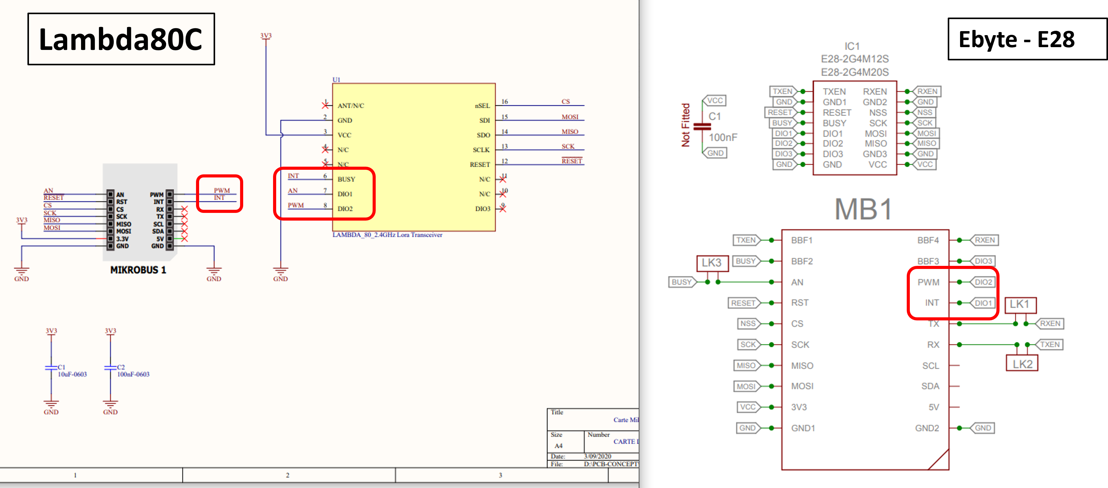
The pinouts of those adapters have some differences.
Two versions of the E28 module exists: 12S & 20S
EByte28 module
AN  <-> Busy
INT <-> DIO1
PWM <-> DIO2

Lambda80C module
AN  <-> DIO1
INT <-> Busy
PWM <-> DIO2

NiceRF SX1280 TCXO module
AN  <-> ??
INT <-> ??
PWM <-> ??
- Geditech's LoRa SX1280 adapter
- Stuart Robinson's (GW7HPW) Breadboard Friendly Board for NiceRF SX1280 Module
- Stuart Robinson's (GW7HPW) Breadboard Friendly Board for Ebyte E28 Module
Have a look into the shop
- Geditech's LoRa Microchip RN2483 (for 433 MHz and 868 MHz ISM bands)
Firmware are into ./Firmware.
Those gateways had 3 LoRa® 2.4GHz channels for Rx and 1 LoRa® 2.4GHz channels for Tx.
- Multitech MTCDT + MCard MTAC-LORA-2G4-3
- SX1280Z3DSFGW1 LoRa® 2.4GHz 3 Channels Single SF Reference Design (included a removable mPCIe card).
- Embit EMB-FEM2GW-O-2G4 (included a removable mPCIe card EMB-LR1280-mPCIe-4x).
Important: ESP32 Wroon 32U had 38 pins and an UFL connector for an external (high gain and directive) antenna. ESP32 Wroon 32D had 38 pins and a PCB antenna. Choose ESP32 Wroon 32U for a better link margin.
- LAMBDA80C-24D @ Farnell (UFL connector + EM shield)
- LAMBDA80C-24S @ Mouser (UFL connector + EM shield)
- EByte E28-2G4M20S @ Aliexpress (UFL connector + EM shield)
- 20-pin stackable headers (x2) for ESP32 : should be resized to 19 pins.
- 8-pin stackable headers (x2) for Mikrobus modules.
- Grove connectors (x3 but optional).
- Diymore 2x18650 Battery Pack @ Aliexpress
- DFRobot Solar Power Manager 5V
- DFRobot Solar Power Manager Micro
- Adafruit Universal USB / DC / Solar Lithium Ion/Polymer charger - bq24074
Plug the PPK2 power source (
VOUT+GND) on3V3+GNDpin (double-row header and Grove connectors) and DO NOT plug the ESP32 throught the mini-USB connector.
For PCB designs, the license is Attribution-NonCommercial-ShareAlike 4.0 International (CC BY-NC-SA 4.0).
For Software, check the license into each directory.
- PCB for ESP32 Wroom 32 (38 pins) + 2 Mikrobus modules + 3 groves connectors (RXTX,I2C,ANA)
- PCB for ESP32 Wroom 32 (38 pins) + 2 Mikrobus modules + 3 groves connectors (RXTX,I2C,ANA) + H-Bridges for driving stepper + Power supply
- Mikrobus adapter for Lambda80 SX1280 module
- Mikrobus adapter for EByte E28 SX1280 module
- Mikrobus adapter for SX1280PATR24 module
- Mikrobus adapter for Miromico FMLR STM SX1280 module
- Mikrobus adapter for NiceRF SX1280 module
- Mikrobus adapter for Microchip RN2483 module
- Mikrobus adapter for RF Solutions RF-LORA-868-SO module
- Mikrobus adapter for Abeeway-Murata Geolocation Module
- Mikrobus protoshield
- Arduino sketches for ESP32 Wroom 32 + E28 Mikrobus module
- Arduino sketches for ESP32 Wroom 32 + Lambda80 Mikrobus module
- Arduino sketches for Wio Terminal + Lambda80 Mikrobus module
- Move UART Grove connector for using Grove cable with ESP32-WROOM-32D (PCB antenna)
- TinyGS firmware for ESP32 Wroom 32 + E28 Mikrobus module
- TinyGS firmware for ESP32 Wroom 32 + Lambda80 Mikrobus module
- TinyGS firmware for ESP32 Wroom 32 + Miromico FMLR STM SX1280 module
- TinyGS firmware for ESP32 Wroom 32 + LR1120 Dev Kit module for such modulations and bands : LoRa SubGHz, LoRa 2.4GHz, LR-FHSS, S-Band (1.9-2.1GHz)
- TinyGS firmware for Wio Terminal + Lambda80 Mikrobus module
- Power consumption study with X-NUCLEO-LPM01A
- RIOTOS firmware for ESP32 Wroom 32 + Lambda80 module (cubesat emulator)
- Test the Geditech's LoRa Microchip RN2483 (for 433 MHz and 868 MHz ISM bands) on second slot.
- Add slots for I2C and UART grove connectors into the two Mikrobus slots (can be used when the Mikrobus slot is not used)
- Add slot for female header in order to plug a low-cost SDCard SPI breakout (useful for data logging)
- Add slot for female/male header in order to plug a low-cost DS1307/DS3231 breakout (useful for timestamping data log entries)
- Add extra slot for power sources (3V3, VCC)
- Add white label for DevEUI and serial number on silkscreen layer
- Add pin for IRQ on GNSS PPS
- Design Fritzing part for the station
- add licenses
- review PCB designs according the Mikrobus specifications v2.0
- add L9616 CAN driver footprint (see) connected to
CAN_TXD = ESP32 – IO25andCAN_RXD = ESP32 – IO26
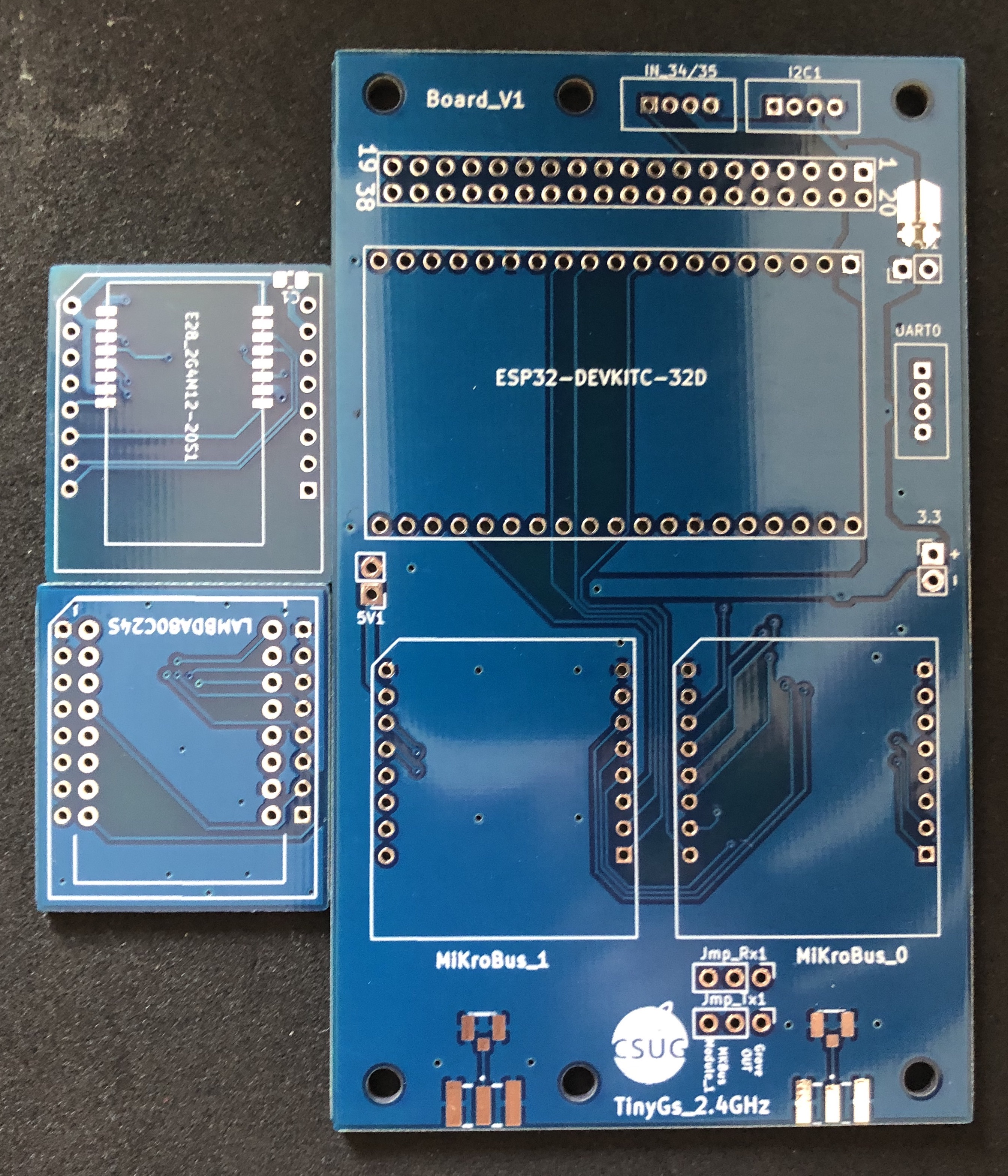
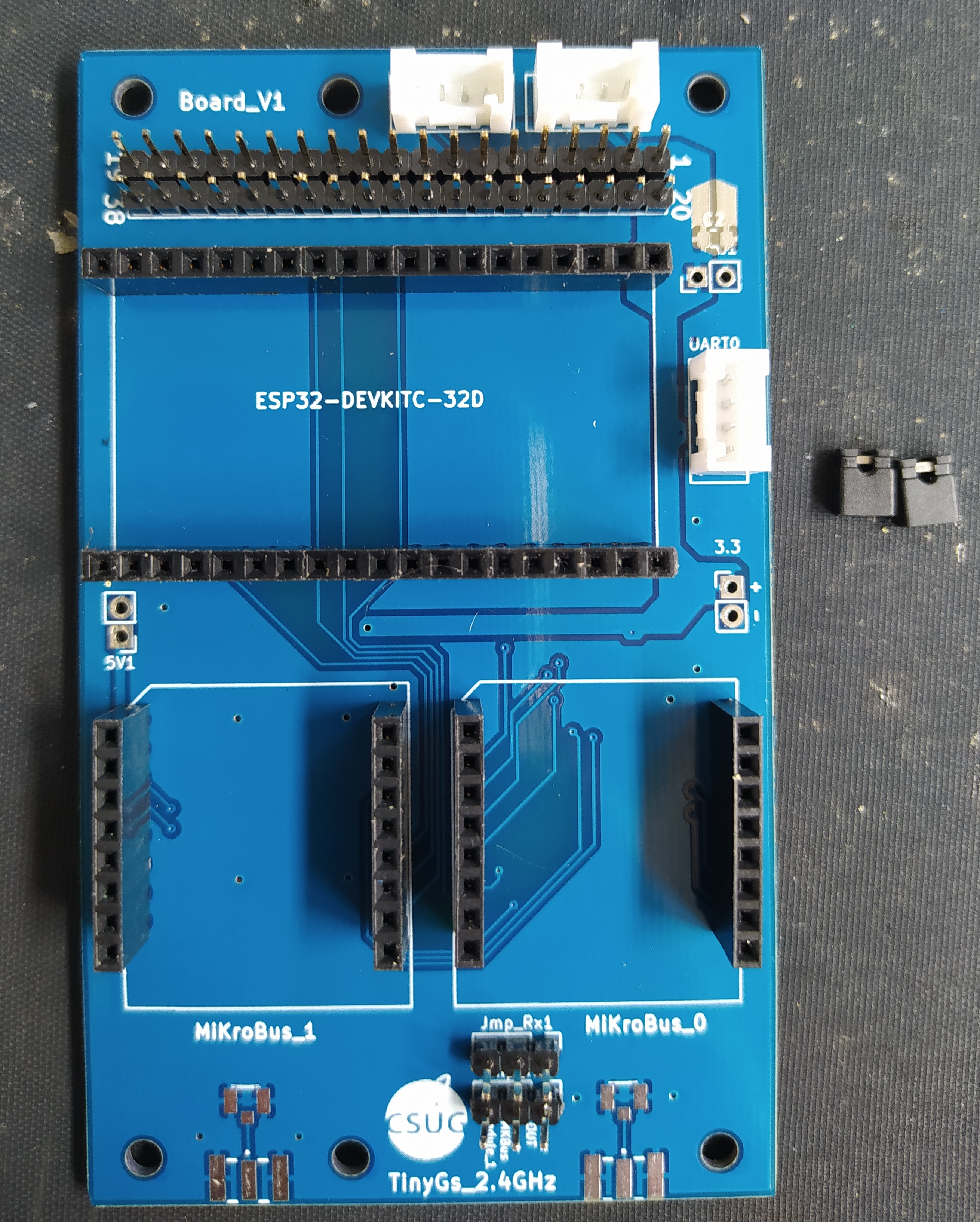
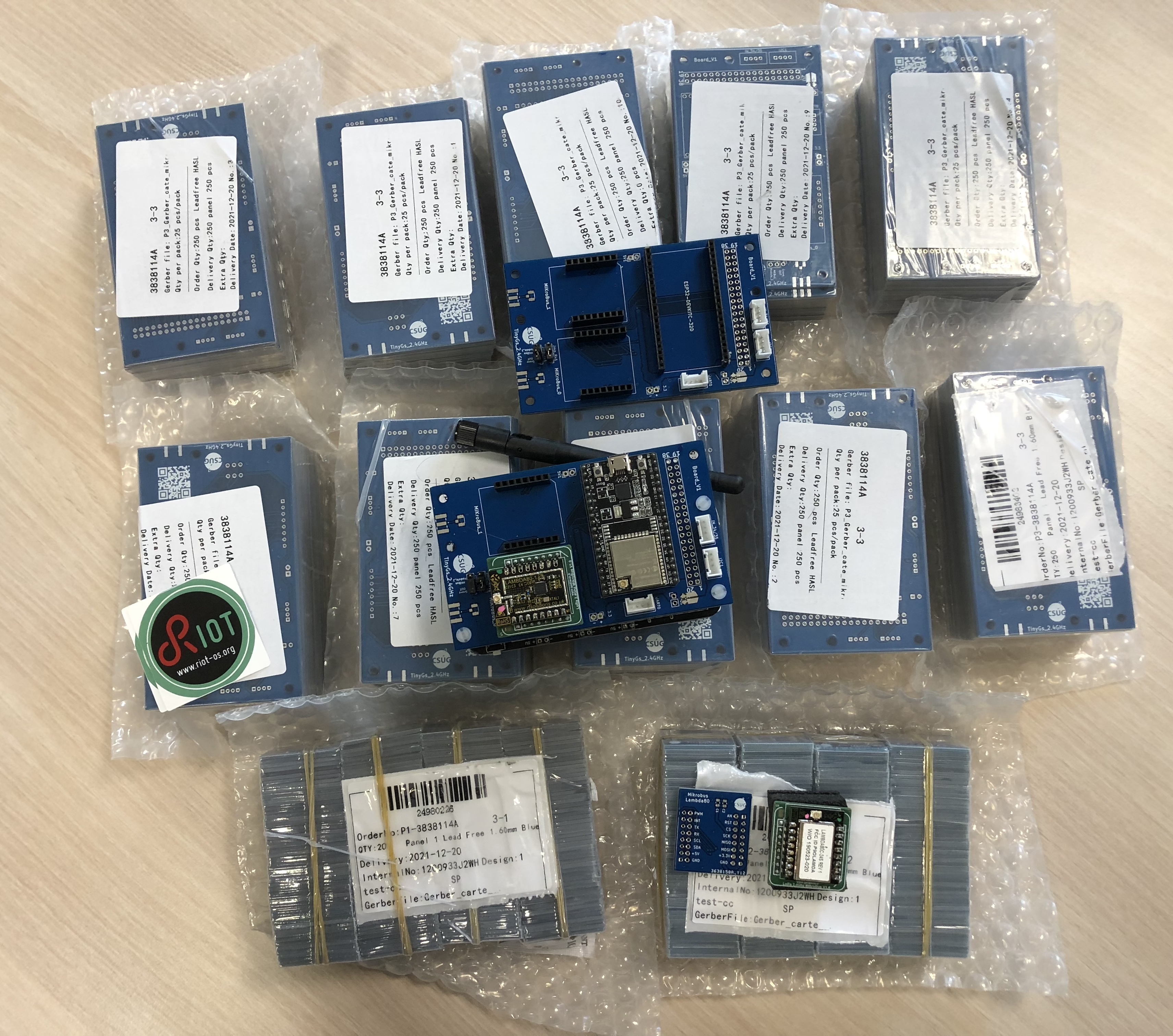
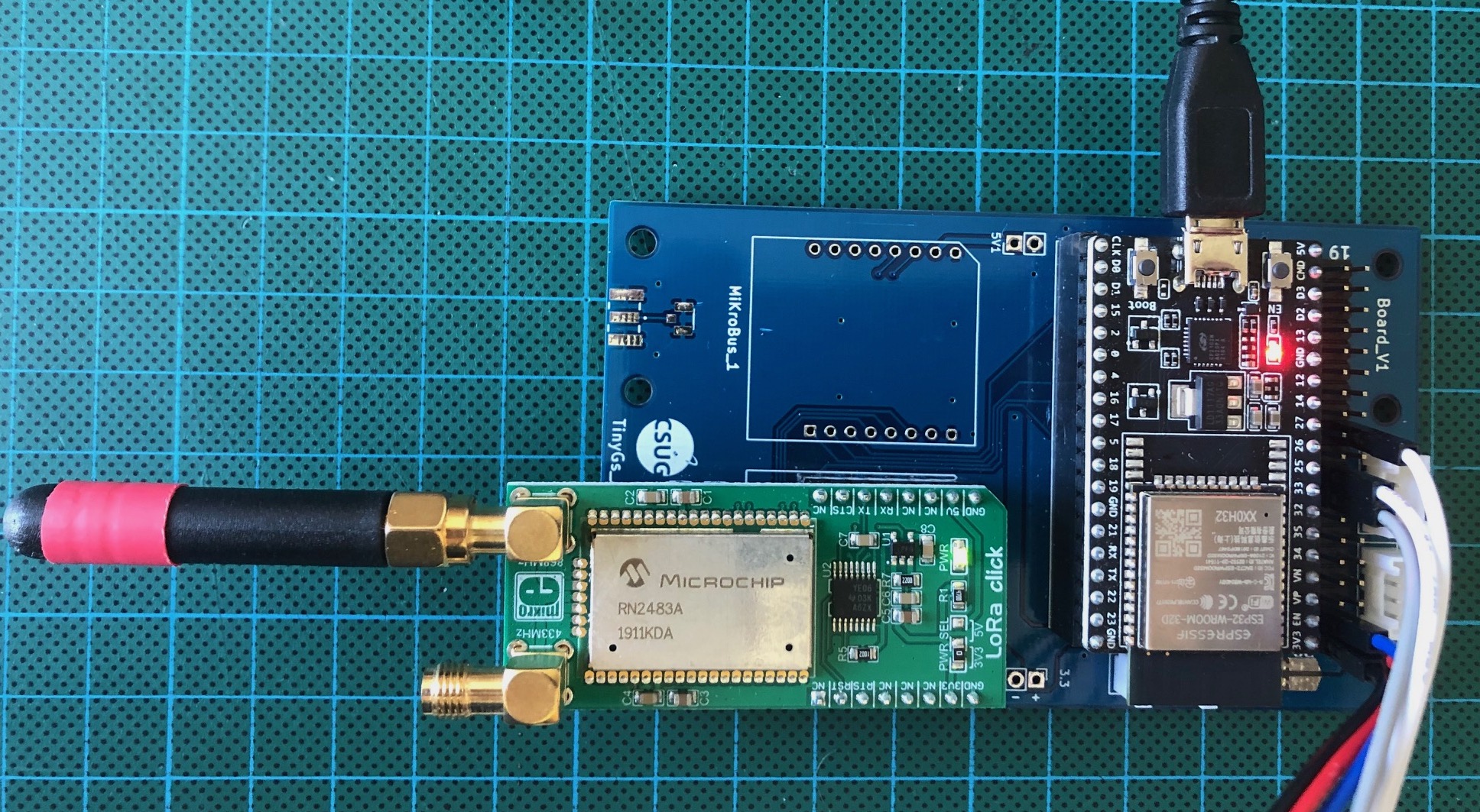
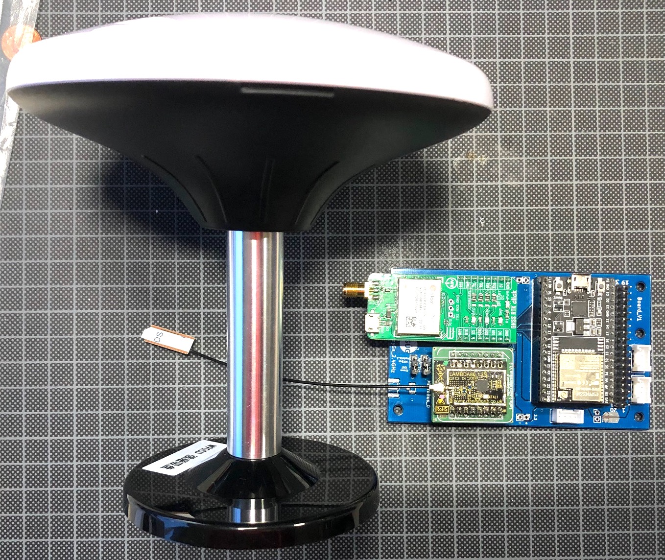
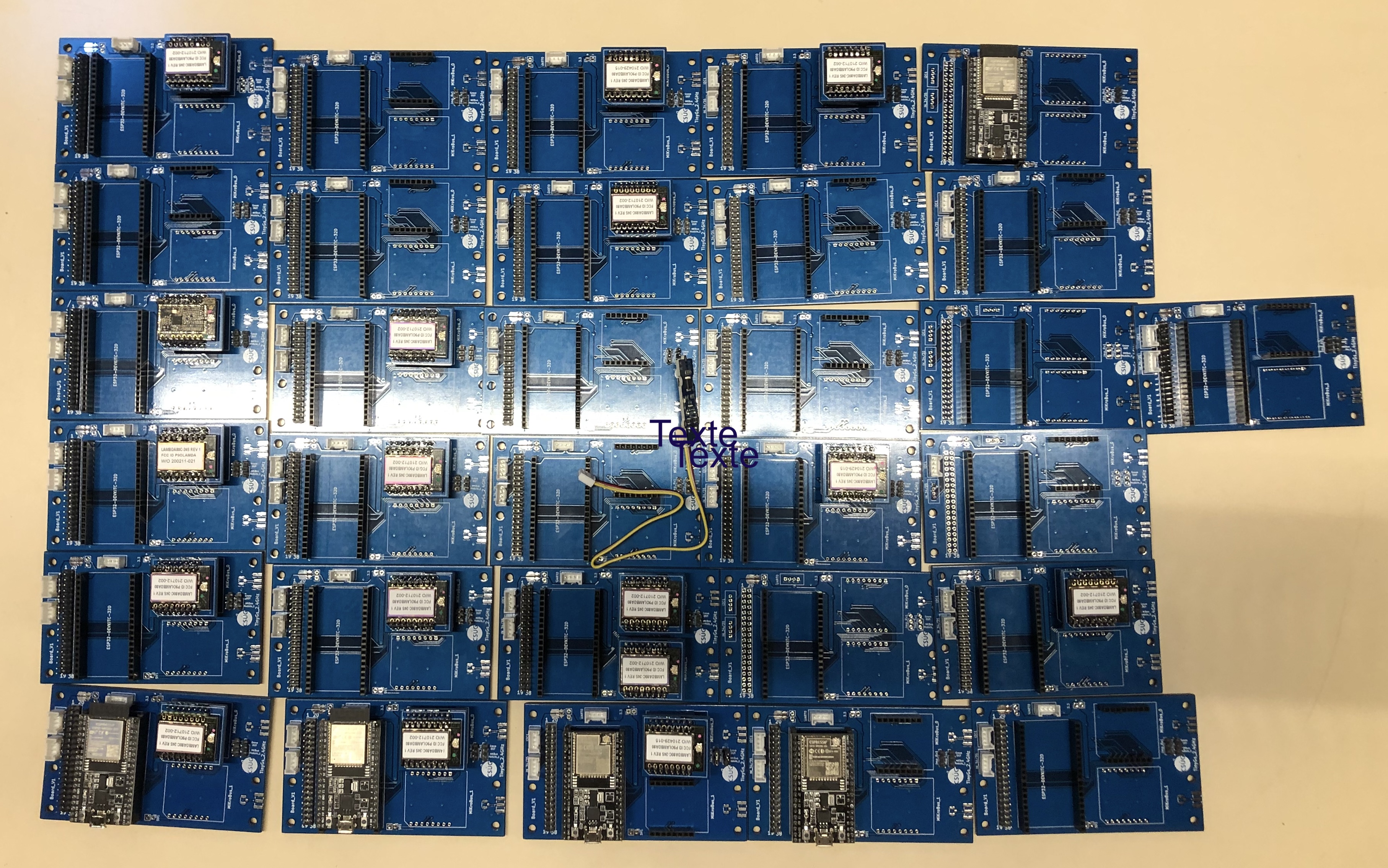
Here the picture of the board_V1, with or without modules. On last picture, a GPS, a magnetometer and a joystick are connected by grove connection.
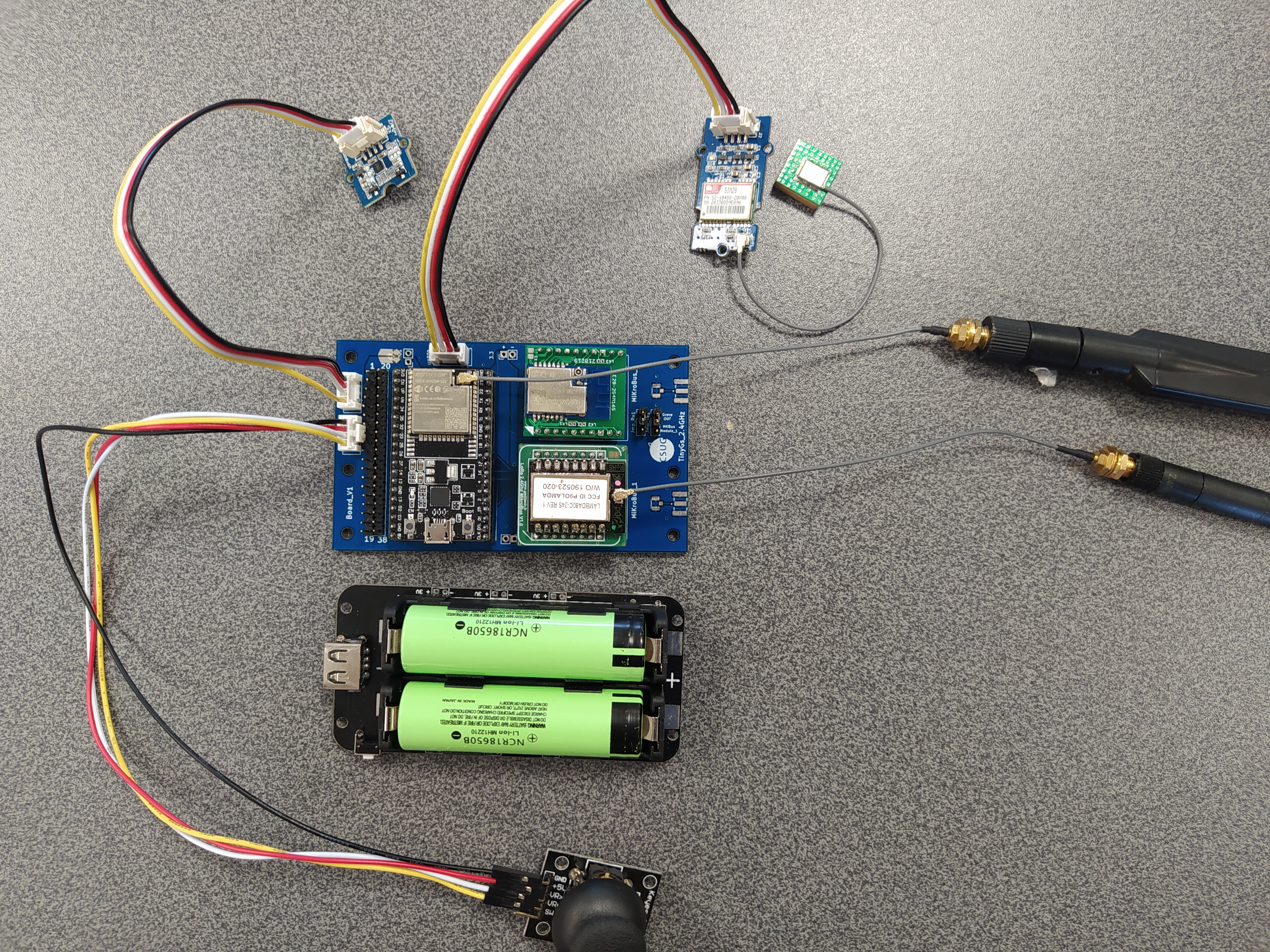 Mounted PCB with Grove boards (Grove Thumb Joystick, Grove LSM6DS3 Accelerometer Gyroscope, Grove GPS) and Lamdba80 and E28 module.
