Quadcopter Flight controller using an ATmega328P Microcontroller.
The aim of this project is to design and build a flight controller circuit for a Quadcopter using an ATmega328P Microcontroller. An ATmega328P Microcontroller is a general purpose microcontroller with 14 digital pins and 6 analogy pins. The flight controller circuir will be integrated with some peripheral electronic components to safely control the drone. The flight controller will receive control signals from RF Transimitter throught RF Receiver, and decode the signals. The Circuit will also read and process the IMU sensor data for drone balancing. Finally the circuit will control speed of blushless motors using PWM signals that will be sent to electronic Speed controllers (ESC).
This project was divided into four main tasks: namely
- Flight Controller Circuit designing and building
- Coding and programming the Flight controller circuit using Arduino IDE
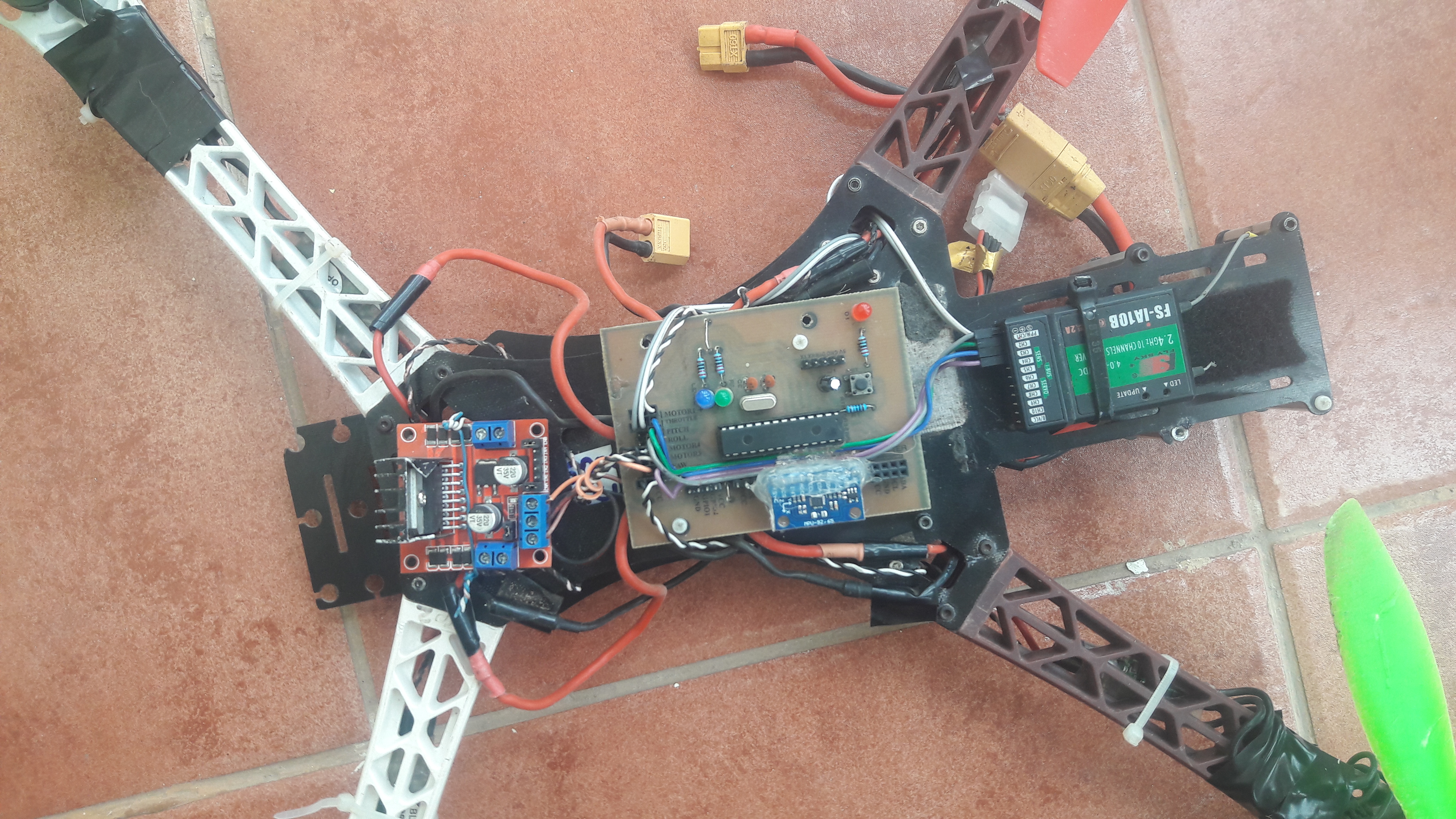
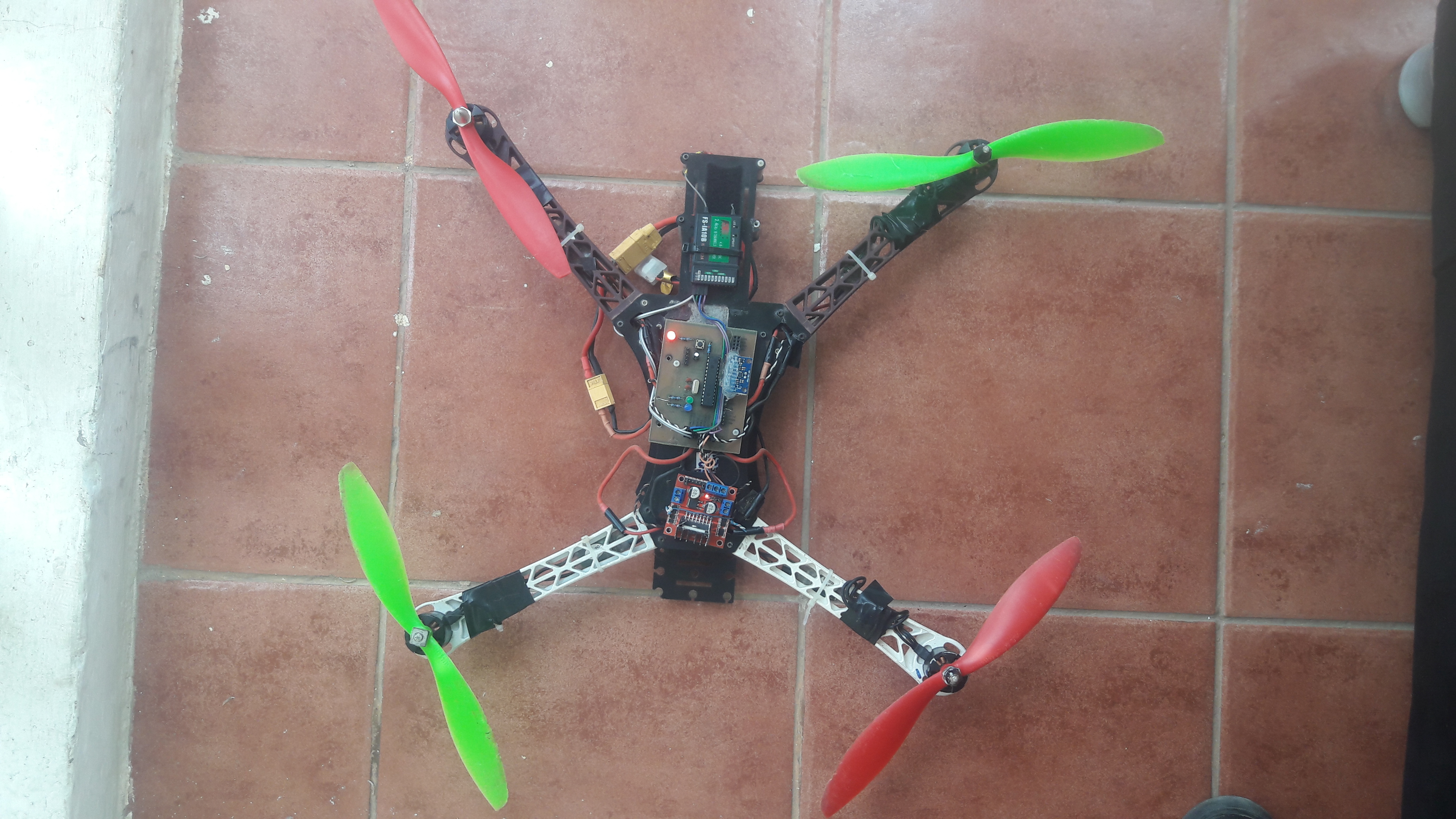
- Mounting the flight controller and other drone components on a DJI F450 frame and
- Testing the flight controller
NOTE
FC stands for Flight Controller
I designed the FC circuit using proteus, then after I printed the circuit and soldered the electronic components on the PCB.
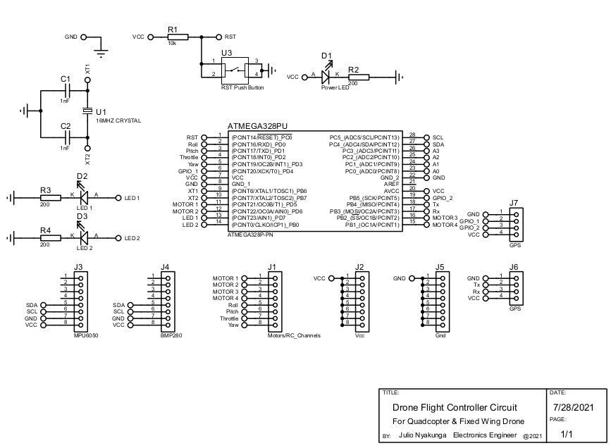
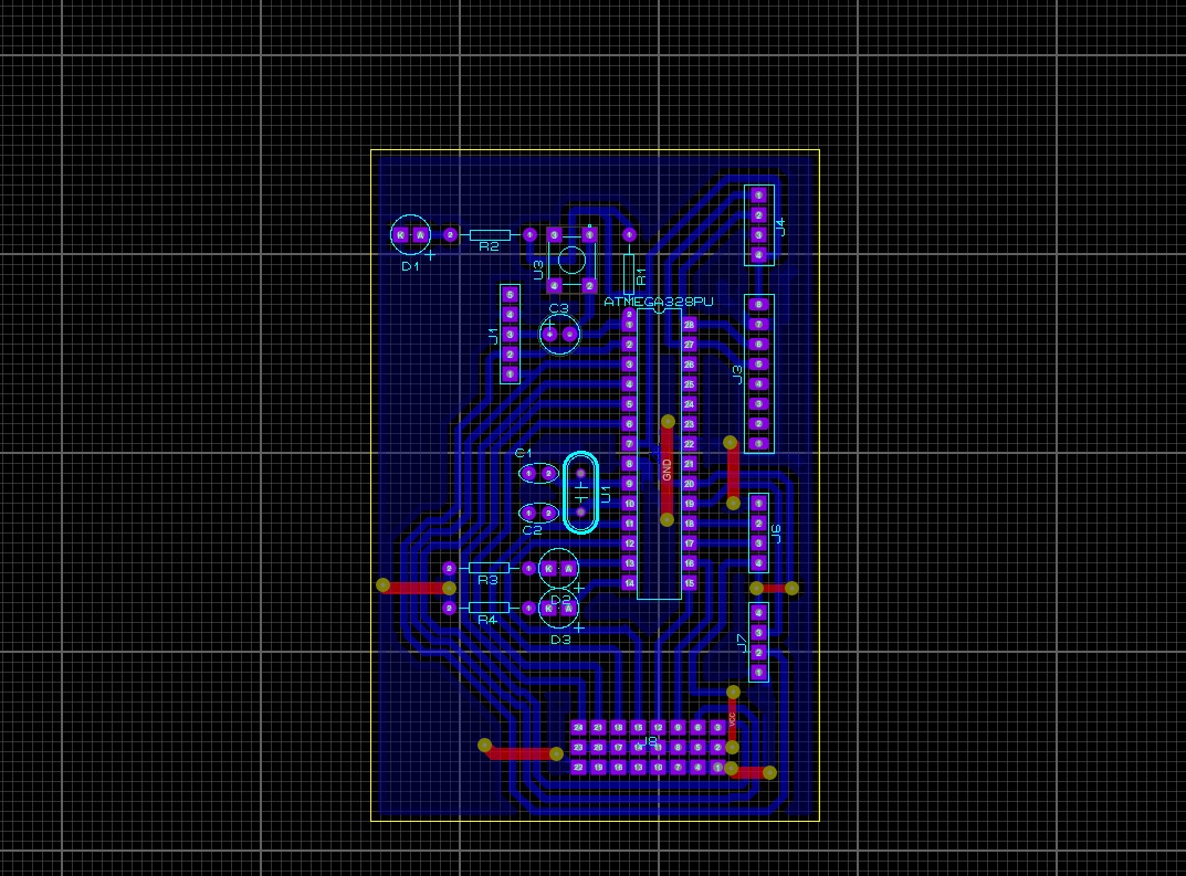
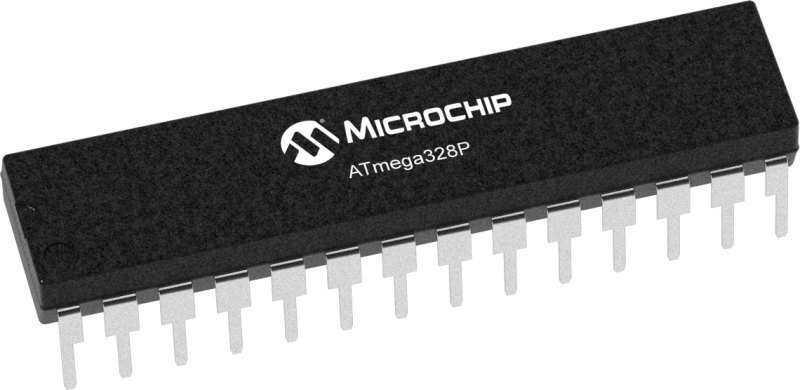
- Atmega328P microcontroller
- 16Mhz crystal oscillator
- 2 22p ceramic capacitor
- 1 Push button switch
- 1 10K resistor
- 3 200/220 Resistor
- 3 LED doide
- 1x8 female pinheader
- 2x4 female pinheader
- 1x4 female pinheader
- Microcontroller chip holder
- MPU-9265 (gyroscope, accelerometer and magnetometer)
.jpeg) The circuit was programmed using Arduino IDE.
The circuit was programmed using Arduino IDE. Arduino Code for the circuit are in the folder named Quadcopter_Flight_Controller in this repository.