Upsy Desky
Just like https://github.com/tjhorner/upsy-desky, but with a DOIT esp32 DevKit v1, an added temperature sensor and some not-so-beautiful wiring ;-).
Iterations
- Initially I forked https://github.com/tjhorner/jarvis-desk to https://github.com/shadow1runner/jarvis-desk; I wired everything as stipulated there, but was not really successful (most likely I had some wires wrong or did some wrong code modifications); anyway, doing more research let to...
- ... https://github.com/shadow1runner/FullyJarvis which in comparison to the former uses one logic shifter less since only the UART connectivity is required; this did work fine, except for the fact that - no matter what I tried changing in code - the screen of the handset never turned off again, and it was the mere fact of not understanding the why which led to
- ... the current iteration which is, again based on 1. (and what you are reading currently); doing it the second time was way smoother, already having gained more experience didn't hurt either ;-)
Changes to upstream
This fork has rather small adjustments from the great upstream repo https://github.com/tjhorner/upsy-desky (also: cf. commit history):
- I had a
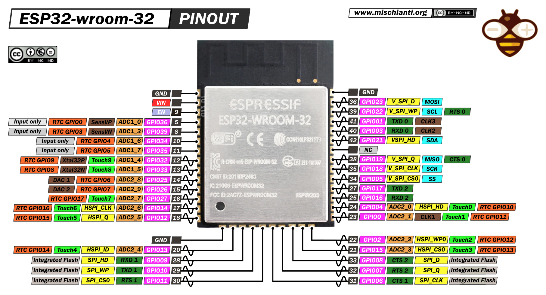
DOIT esp32 DevKit v1at hand, which also features anESP32-WROOM-32(just as upstream does), but:- it has voltage regulators from 5V to 3.3 V already built-in
- can be powered from 5V (provided by the desk) via its
VINpin [1]
- thus, there was no need of having:
- the
CP2102NUSB/UART adapter - the USB-C receptacle
- 3V3 voltage regulator
- the
- changed the default units to metric units as per SI standard
- changed the GPIO pins based on the PinOut shown below

In comparison to the upstream pinout:
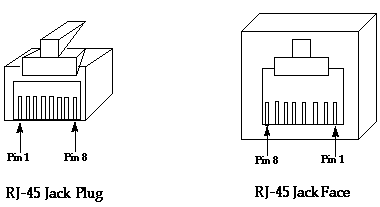
| RJ45 Pin [^0] | Color LAN cable | Schematic Name | Upstream ESP32 mapped Pin | New DOIT esp32 DevKit v1 GPIO Pin | My wire color to esp32 | Note |
|---|---|---|---|---|---|---|
| 1 | orange/white | DESK_1 |
18 |
GPIO32 |
blue | button_m_pin |
| 2 | orange | DESK_2 |
17 |
GPIO16 (RX2) |
white | UART RX[^1], 5V |
| 3 | green/white | GND | N/A (GND) | N/A (GND) | ||
| 4 | blue | DESK_4 |
16 |
GPIO17 (TX2) |
gray | UART TX[^1], 5V |
| 5 | blue/white | +5V | N/A (+5V) | N/A (+5V) | ||
| 6 | green | DESK_6 |
19 |
GPIO33 |
green | button_bit4_pin |
| 7 | brown/white | DESK_7 |
21 |
GPIO25 |
yellow | button_bit1_pin |
| 8 | brown | DESK_8 |
22 |
GPIO26 |
purple | button_bit2_pin |
[^0]
[^1] Note: The UART mappings are exchanged in comparison to upstream:
- the original did the swapping during the final mapping to the IC
- this one does it as part of the logic level shifters
- upstream:
- uart.tx_pin:
16 - standing_desk_uart_rx_pin:
17
- uart.tx_pin:
- local:
- standing_desk_uart_tx_pin:
GPIO17 - standing_desk_uart_rx_pin:
GPIO16
- standing_desk_uart_tx_pin:
Thus:
GPIO17(UART2TX) is mapped to theDESK_4(RX) port (upstream:16->DESK_4)GPIO16(UART2RX) is mapped to theDESK_2(TX) port (upstream:17->DESK_2)
How To...
Set up a development environment?
- As usual: DON'T try getting it running on Windows, just get a Linux somewhere (e.g., a Raspberry) and you are good to go via running setup.sh
- useful commands, after
cd firmware:-
esphome run jarvis_withsecrets.yamlcompiles and flashes the firmware to the board; note that you shortly need to press itsBOOTbutton such that the flashing can happenNote: this requires
firmware/secrets.yaml(not committed to remote), it should look as follows:wifi_ssid: TODO1 wifi_password: TODO2
-
esphome run debug.yamlin case you need more information -
esphome logs debug.yamlfor connecting toLOGGER(UART0)
-
Connect to upsy-desky the very first time?
fully-jarvisis configured to auto-reconnect to known WiFi networks; in case this fails, it goes into AP mode and spawns a network namedfully-jarvis- connect to said WiFi, using the initial password
Einstieg00 - once there, it asks you to join a "real" WiFi, simply select one from the list and enter the password
fully-jarviswill reboot and (try to) connect to known WiFi networks
Change initial settings?
- after connecting to a known WiFi network (cf. Connect to upsy-desky the very first time?), you should be able to connect via http://fully-jarvis.local/
- otherwise check your home network for a the IP address of a device named
fully-jarvis - there you can change settings (like units etc.)
- make sure to press the
Upsy Desky Restartbutton once done such that the settings are persisted in flash and take effect
Perform an upgrade? (e.g., after incorporating upstream changes)
- Rebase and push changes to
originNote:
pip install --upgrade esphomemight be worthwhile in case you haven't fiddled with esphome for a while - now either:
- On gitHub:
- start a new release which will cause the CI pipeline to create a new firmware
- download the release binaries, the
firmware.binis the file you need - navigate to your upsy-desky via a browser and upload said binaries which will perform an OTA upgrade
- On your local development environment:
- run
esphome run jarvis_withsecrets.yaml, which compiles and flashes the firmware to the board; note that you shortly need to press itsBOOTbutton such that the flashing can happen
- run
- On gitHub:
Upstream
- For any further information see upstream https://github.com/tjhorner/upsy-desky/
Wiring
Cf. pcb folder
Note: 44e848bba46ff77500eab2dd5d7e8c4475432bc6 and 44b5dc0cdc3e29ba02147292698e92e65c89b479 tried to mitigate connectivity issues when the board, after boot, just didn't want to connect to Wifi; these did not help though (and have thus been reverted); what brought long-term remedy was connecting the USB board via USB (powered by one of the monitors), then enough stable voltage (?) lead to a clean boot.
Additional Documentation
You can find everything you need in the GitHub wiki.
Licenses
The ESPHome configs are licensed under MIT; everything else (enclosure and PCB design) are CC BY-NC-SA 4.0. The appropriate license files are available in the root of the repo.
References
[1] PinOut and schematics of DOIT ESP32 Devkit V1: https://github.com/SmartArduino/SZDOITWiKi/wiki/ESP8266---ESP32