With this setup you can track how much centimeters (CM) an object is placed from the sensor and send that data to your own server. With this data you can for example:
- Track if somebody or something is still on it's place
- Track if somebody or something is to close or to far from an object.
- Track if there is any activity in the environment
At the server you can configure what alert you want to give. In this tutorial a LED will light up.
For this tutorial I expect you have at least a little understanding of:
- The programming language C++ (or JavaScript)
- How to work with your command prompt (Windows) or Terminal (Mac).
- How to set up a own live node server (if you want to communicate with a live environment server)
- Overview
- What do we need?
- Set up the hardware
- Set up the software
- Set up the server
- Add the code to do the magic
- Magic!
- Demo
This IoT project allows you to set up a simple distance sensor that is connected with a NodeMCU EPS8266 board and pushes it's data to a Node Server environment. The Node server allows you to:
- display the distance between a distance sensor and an object (or person).
- manipulate a output source on your NodeMCU board (in our case a led).
- Configure when and how a output source should behave.
- NodeMCU ESP8266 + WiFi board
- HC-SR04 Distance Sensor
- NodeMCU EPS8266 drivers
- Arduino program
- Breadboard
- 1x red led
- 1x yellow led
- 1x green led
- 8-10 boardboard wires.
- Optional: resistors
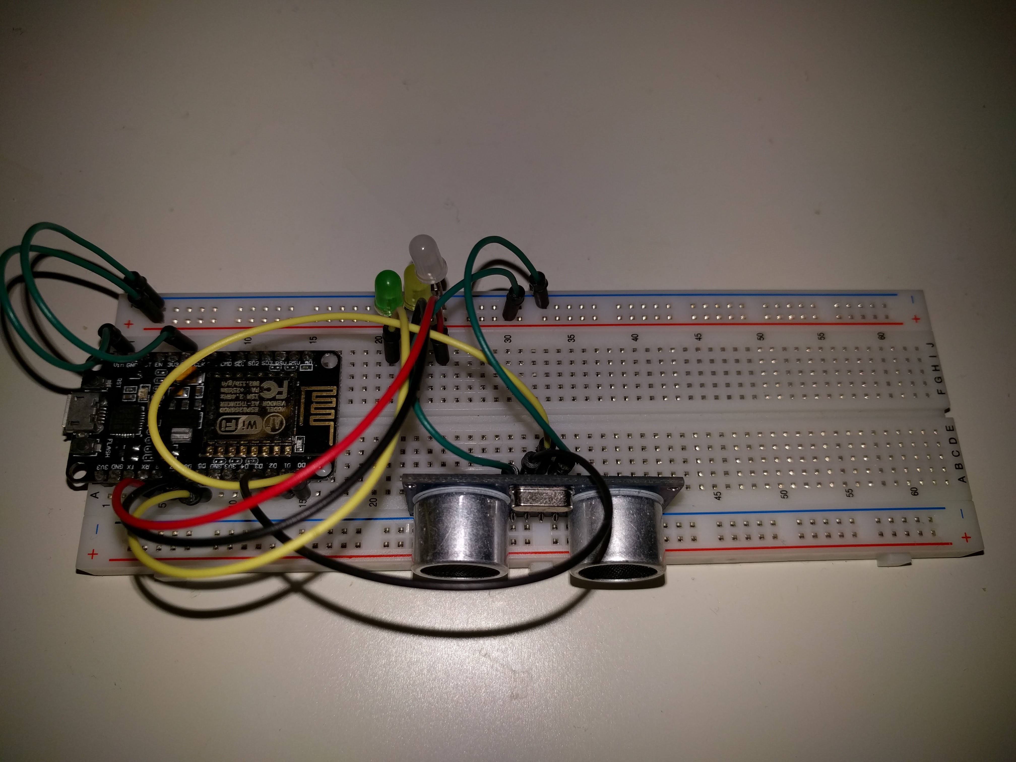
You should have this ready to go:

Here's how schematic overview of how to connect the sensor and the LEDs.
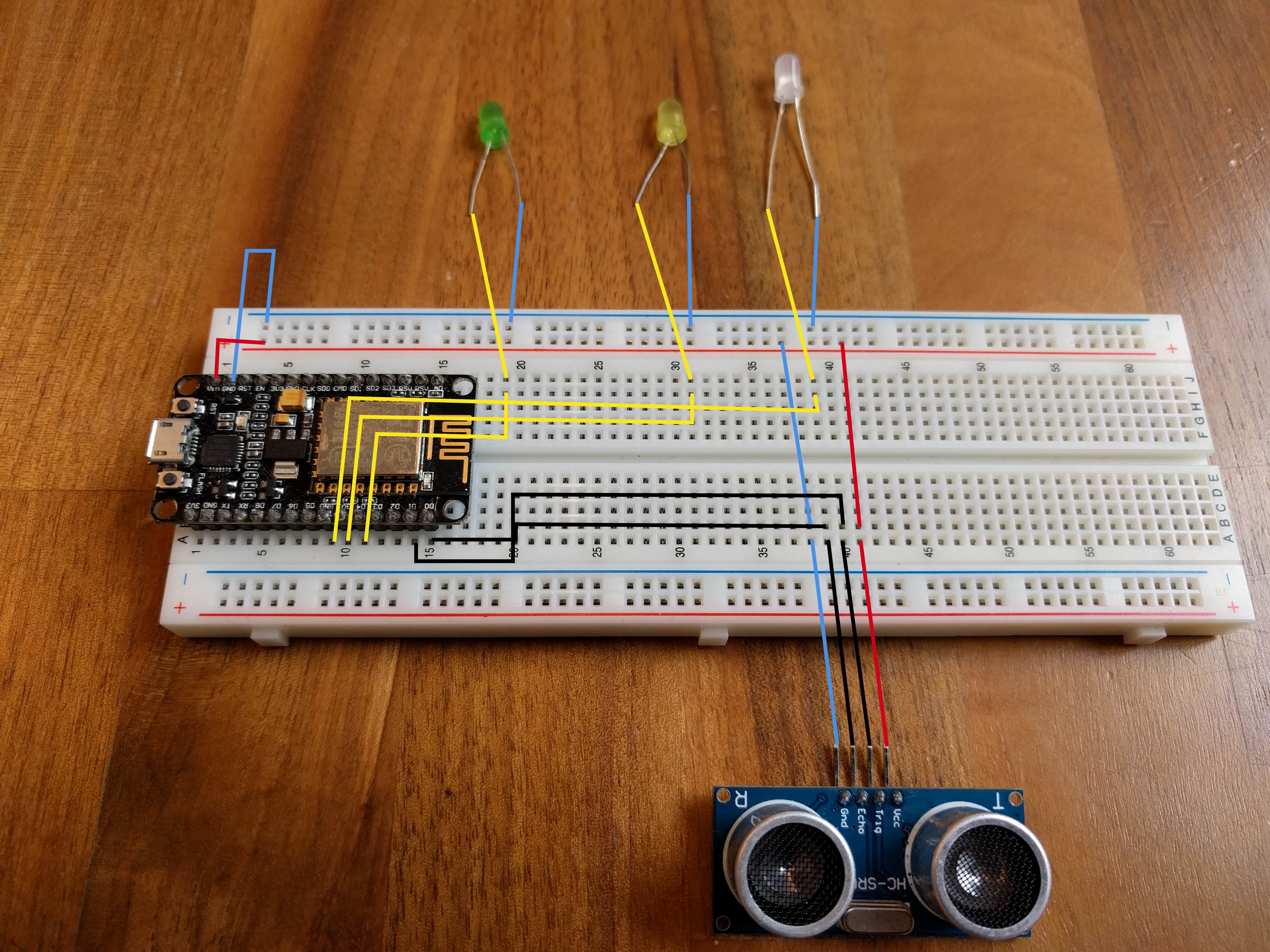
If you want a step by step instruction of how to connect everything, you can keep reading the steps below. If this schematic overview is enough for you to set up the hardware, skip to chapter 4: set up the software.
We'll start putting the NodeMCU board at the right place on your breadboard. I would suggest you do it in the center bottom so you have plenty of space left to insert your distance sensor and the LEDS.
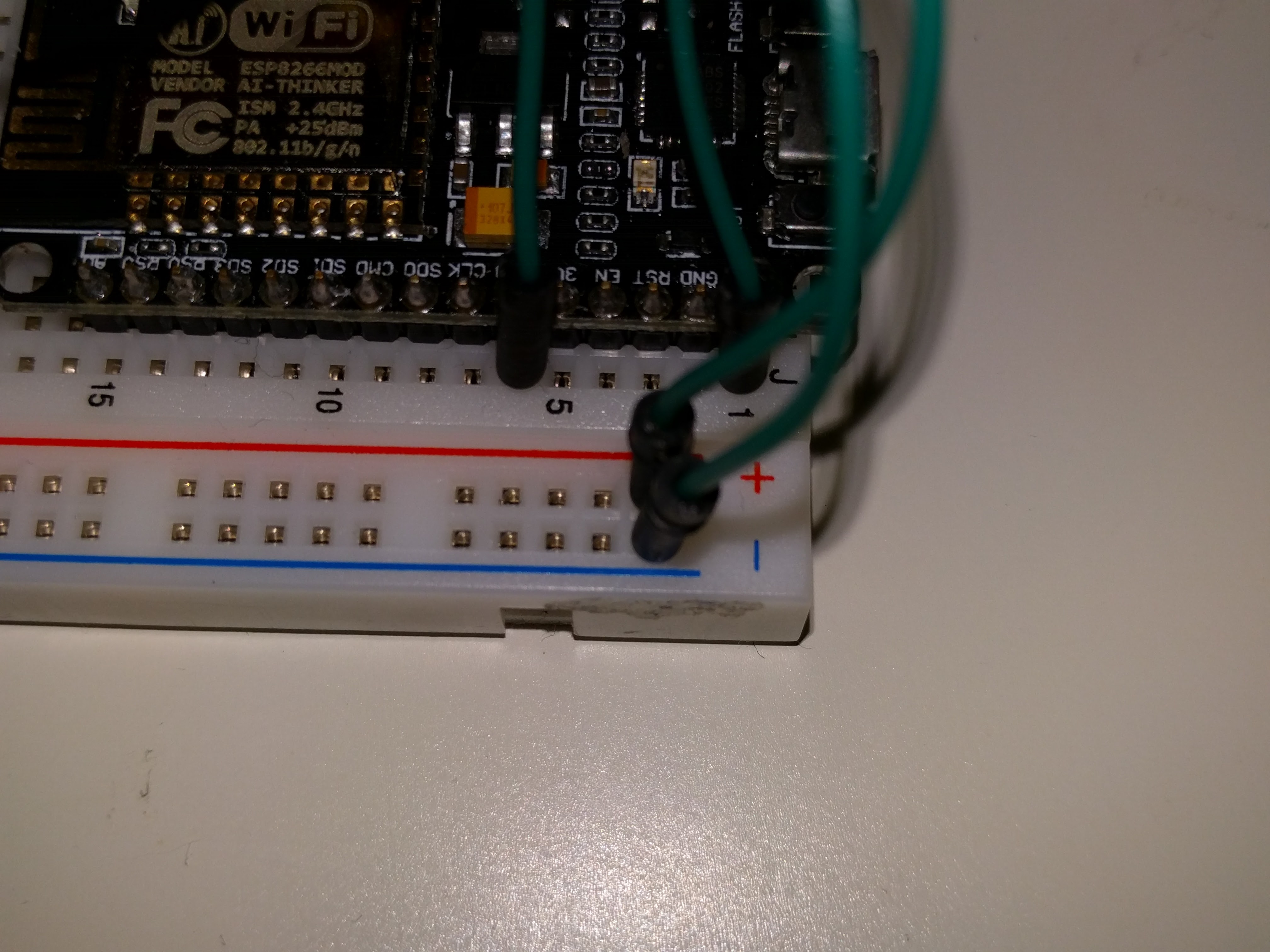
Take two wires (preferable a red and blue one) connect the 5v (red wire) to the + (plus) and the ground (blue wire) to the - (min) part of your breadboard.
Now we have the ingredients to make our sensors and LEDs work.
The LEDs will indicate how far away you your object is from your distance sensor. On the Node Server, which we will set up in just a bit, we can configure which led needs to light up manually.
There are different ways to connect your led. I prefer to connect the ground side of the led into our ground row.
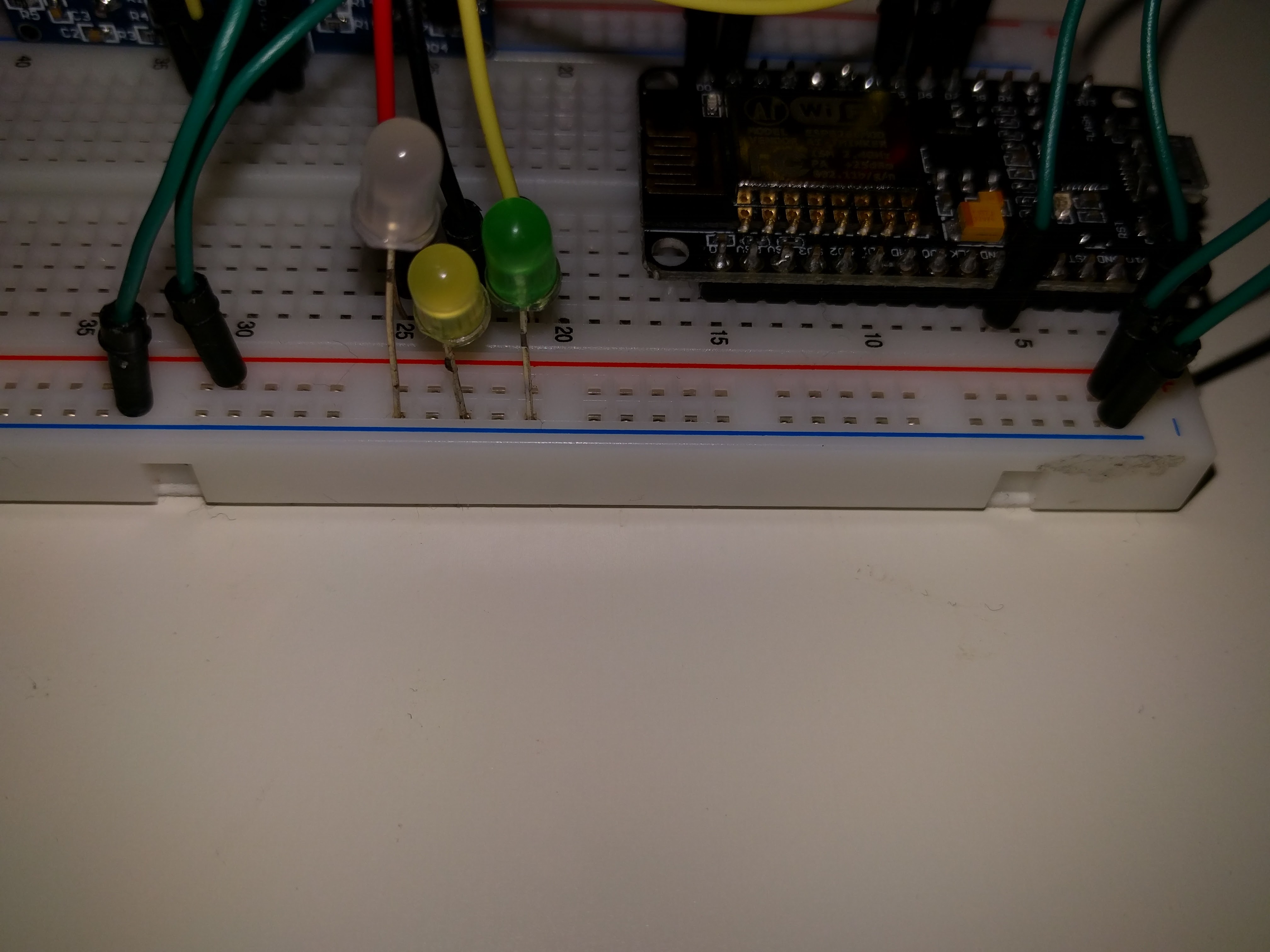
On the other side of the leds we'll need 3 more wires to connect them to the output of the NodeMCU board. For the sake of this tutorial, connect them at the following ports:
- Green: D5
- Yellow: D6
- Red: D7
The distance meter has 4 connectors we need to connect with the breadboard wires.
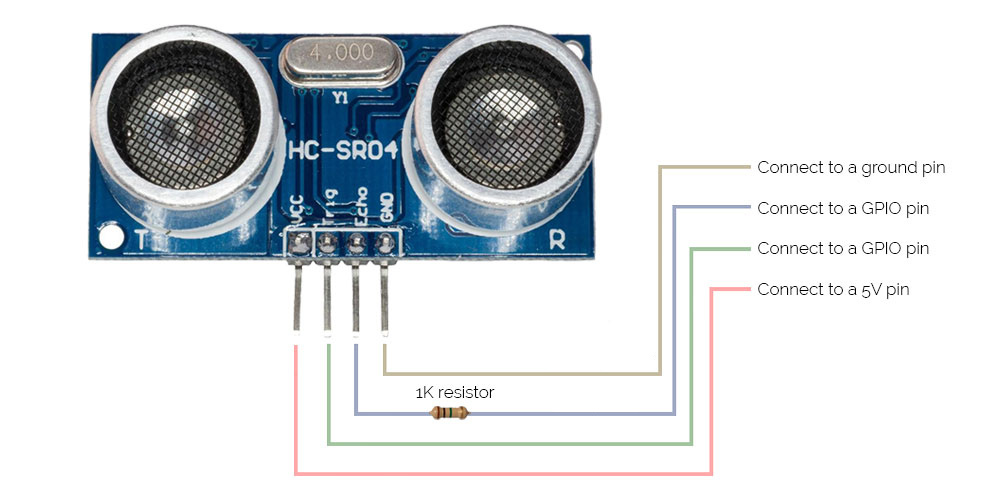
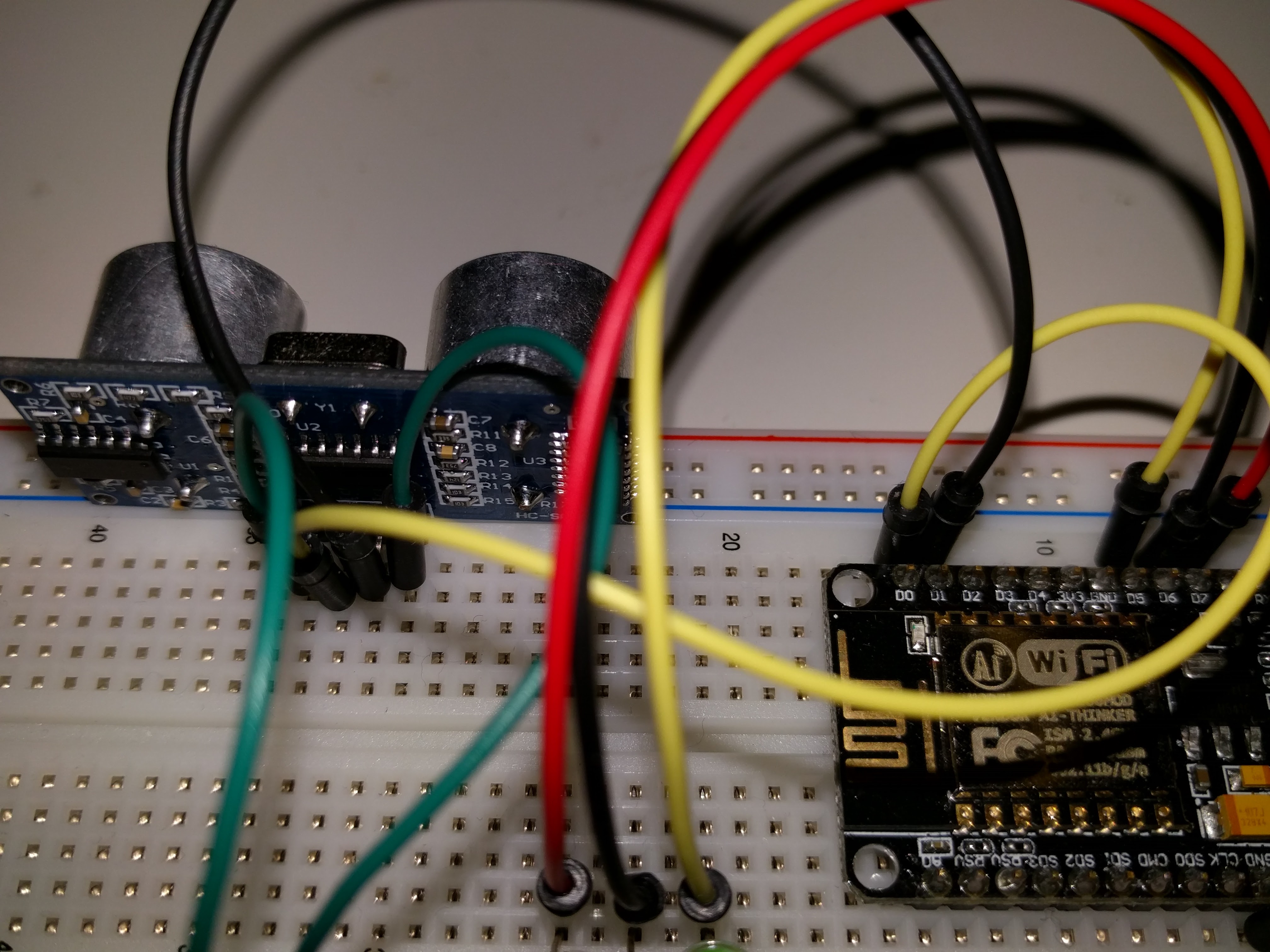
- Connect the 5v to our own created + on the breadboard
- Connect the ground on our own created - on the breadboard.
- Connect the echo on the D0 port
- Connect the trigger on the D1 port
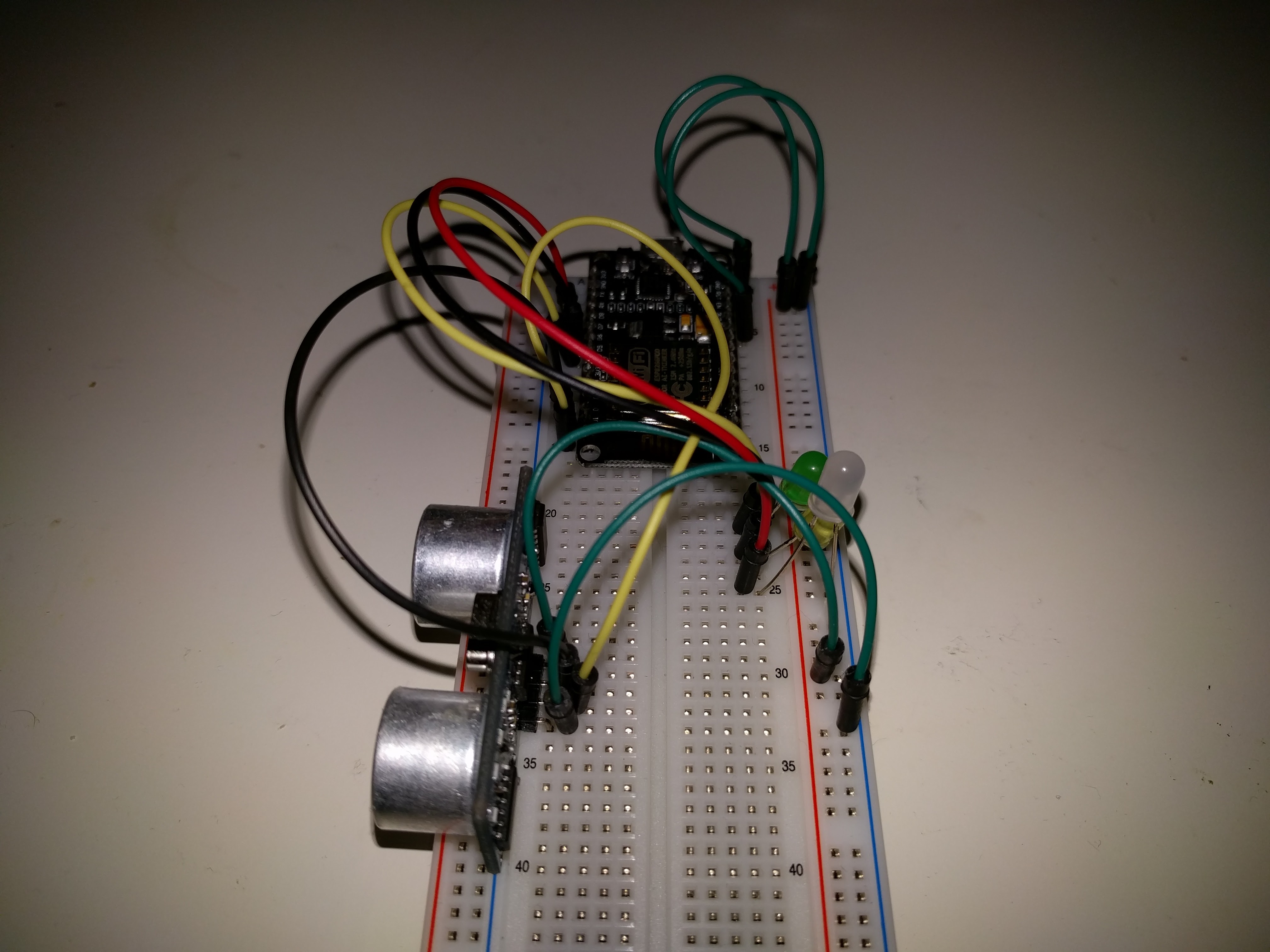
That should do the trick! If your done, it will look like this:
You will need the Arduino software and the drivers for the NodeMCU ESP8266 for this part.
You can download the Arduino software at the official site of Arduino
Install the software by following the standard installation procedure and launch the program after it's finished. You should see an empty editor window.
Next we need to install the necessary driver so the Arduino software can work with out NodeMCU board.
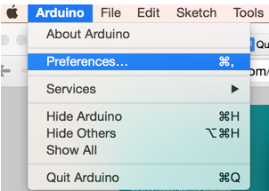
1 - Go to Arduino > Preferences (in the menubar)
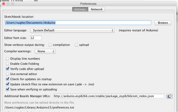
Add the following link at the "Additional Boards Manager URLs"
http://arduino.esp8266.com/stable/package_esp8266com_index.json
2 - Go to Tools > Board > Boardmanager (in the menubar)
3 - Search for 'esp'
4 - Select the block and click 'install'
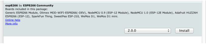
5 - The drivers should be installed now
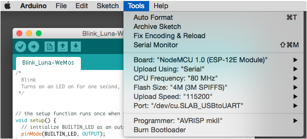
6 - Go to tools and make sure your settings look like this:
It's finally time to set up our server. This tutorial will show you how to set it up locally. This tutorial won't explain how to set up this server on a live environment with a own domain. My advice: check out Digital Ocean how to set up a node server on an live environment.
Clone this git repository to the folder where you want the store this project local on your computer. You need to open your Command Prompt (Windows) or Terminal (Mac) to execute this.
git clone https://github.com/sennykalidien/IoT-NodeMCU.git
cd IoT-NodeMCU
git checkout iot-senny
Download the files from the Github resporitory: Server repository
After the git repository is cloned with the right branch, install all node modules with:
npm install
After the installation you can start your server locally with the following command:
npm start
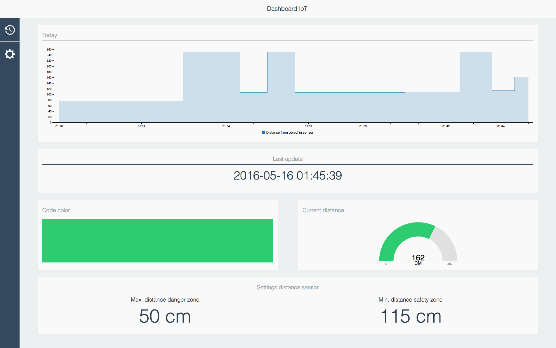
You can view the UI by going to localhost:3010
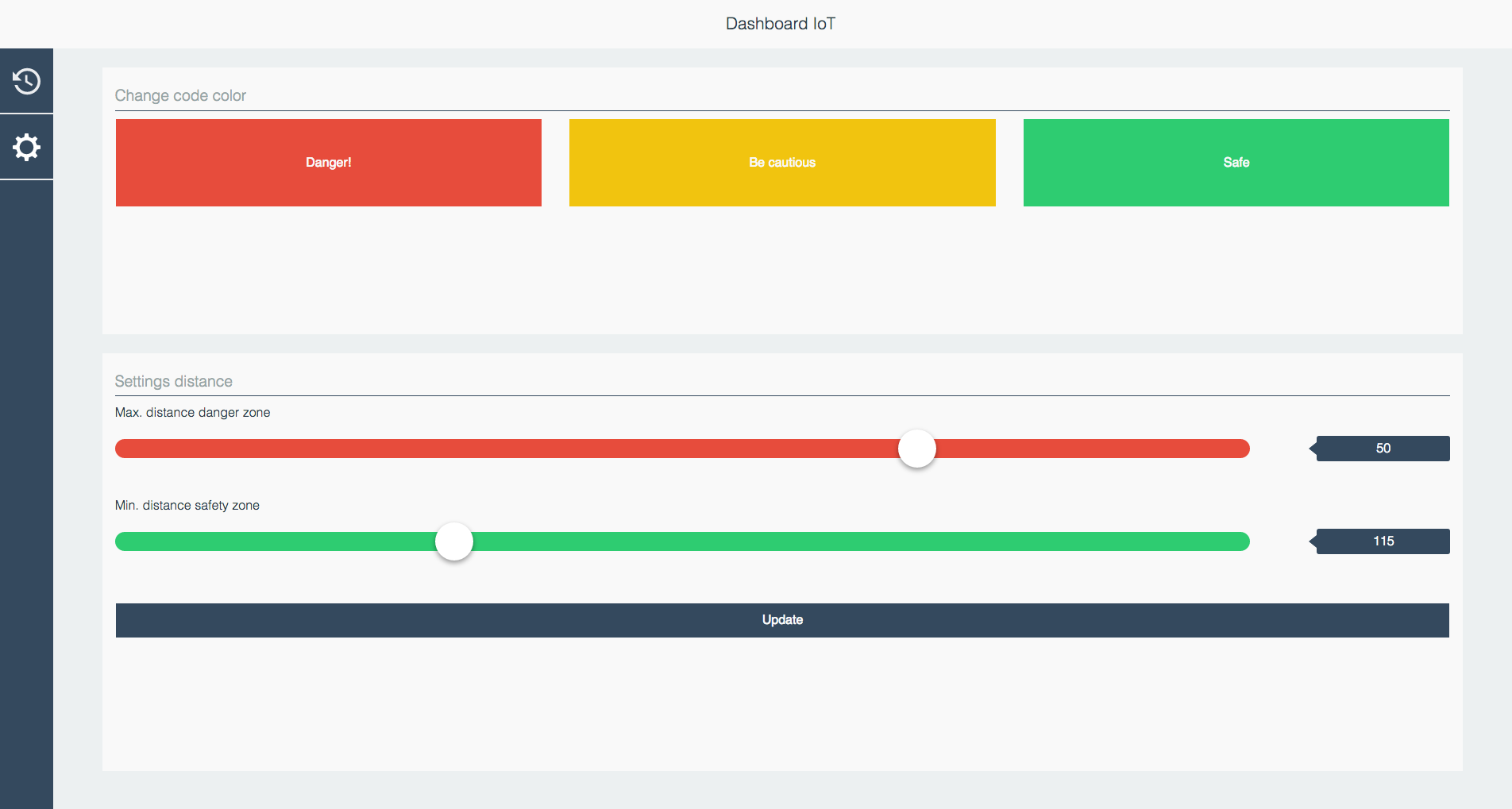
The UI consist of two pages:
1 - Homes page - An overview of the data
2 - Settings page - configure the input and output of your board
Good news: you're almost done! We only need to add the code to make our NodeMCU behave properly. It will need to do two thing:
- A GET request - Get the status of our output (LED) from the server.
- A POST request - Post the data of our distance sensor to the server.
Open a new file in Arduino by navigating to Sketch > Include libraries and add these libraries to your project:
- ESP8266WIFI (should already be available when we installed the drivers for our NodeMCU board)
- ArduinoJson download here
How to add a external library:
If you don't have the necessary libraries available on your computer you need to download the library and manually add it so you can use it in the Arduino software.

The libraries can be added in your documents folder > arudino > library

MAKE SURE YOU PUT THE WHOLE FOLDER IN THERE AND NOT JUST THE FILES.
If you've selected the libraries it will add the following on top of your editor window:
#include <ESP8266WiFi.h>
#include <ArduinoJson.h>
Next we'll set up your WiFi connection.
// Hotspot
const char* ssid     = "ENTER YOUR SSID";
const char* password = "ENTER YOUR PASSWORD!";
Add this for setting up to information to our server
// Hosts
const char* host     = "iot.directzichtbaar.nl"; // Your domain
String path          = "/api/status/output"; // This will go to iot.directzichtbaar.nl/api/status/output to retrieve the status of our LEDS.
const int httpPort   = 80;
Here's the code to set up the input & output ports of our NodeMCU board.
// LED Pins
const int ledPinGreen   = D5;
const int ledPinYellow  = D6;
const int ledPinRed     = D7;

// Range Pins
const int echoPin       = D0;
const int trigPin       = D1;

// Distance
int maximumRange = 250; // Maximum range needed
int minimumRange = 0; // Minimum range needed
long duration, distance; // Duration used to calculate distance

WiFiClient client;
Just copy and paste the code below without changing anything!!
void setup() {
  //set range sensor
  pinMode(echoPin, INPUT);
  pinMode(trigPin, OUTPUT);

  //set led pins
  pinMode(ledPinGreen, OUTPUT);
  pinMode(ledPinYellow, OUTPUT);
  pinMode(ledPinRed, OUTPUT);


  //set serial
  Serial.begin(9600);

  //set wifi
  delay(10);
  Serial.print("Connecting to ");
  Serial.println(ssid);

  WiFi.begin(ssid, password);
  int wifi_ctr = 0;
  while (WiFi.status() != WL_CONNECTED) {
    delay(500);
    Serial.print(".");
  }
  //show when wifi is connected
  Serial.println("WiFi connected");
  //Serial.println("IP address: " + WiFi.localIP());
}
This is the loop our code needs to repeat. We want out board to do a GET request to retrieve the status of our LEDS frequently, so we set up a delay so it won't do it every send. The same we'll configure for our POST request.
void loop() {
  if (!client.connect(host, httpPort)) {
    Serial.println("connection failed");
    return;
  }

  getNetworkData();
  delay(2000);
  sendNetworkData();
  delay(30000);
}
// GET DATA
void getNetworkData() {
  client.print(String("GET ") + path + " HTTP/1.1\r\n" +
               "Host: " + host + "\r\n" +
               "Connection: keep-alive\r\n\r\n");

  delay(500); // wait for server to respond
  Serial.println("Getting data");

  // read response
  String section = "header";
  while (client.available()) {
    String line = client.readStringUntil('\r');
    // Serial.print(line);
    // we’ll parse the HTML body here
    if (section == "header") { // headers..
      //Serial.print(".");
      if (line == "\n") { // skips the empty space at the beginning
        section = "json";
      }
    }
    else if (section == "json") { // print the good stuff
      section = "ignore";
      String result = line.substring(1);

      // Parse JSON
      int size = result.length() + 1;
      char json[size];
      result.toCharArray(json, size);
      StaticJsonBuffer<200> jsonBuffer;
      JsonObject& json_parsed = jsonBuffer.parseObject(json);
      if (!json_parsed.success())
      {
        Serial.println("parseObject() failed");
        return;
      } else {
        Serial.print("parseObject() success, color: ");

        // Make the decision to turn off or on the right color LED
        if (strcmp(json_parsed["led"], "red") == 0) {
          digitalWrite(ledPinYellow, LOW);
          digitalWrite(ledPinGreen, LOW);
          digitalWrite(ledPinRed, HIGH);

          Serial.println("red");
        }
        if (strcmp(json_parsed["led"], "yellow") == 0) {
          digitalWrite(ledPinRed, LOW);
          digitalWrite(ledPinGreen, LOW);
          digitalWrite(ledPinYellow, HIGH);

          Serial.println("yellow");
        }
        if (strcmp(json_parsed["led"], "green") == 0) {
          digitalWrite(ledPinRed, LOW);
          digitalWrite(ledPinYellow, LOW);
          digitalWrite(ledPinGreen, HIGH);

          Serial.println("green");
        }
      }
    }
  }
}
// Send data
void sendNetworkData() {
  Serial.println("Sending data");

  /* The following trigPin/echoPin cycle is used to determine the
  distance of the nearest object by bouncing soundwaves off of it. */
  digitalWrite(trigPin, LOW);
  delayMicroseconds(2);

  digitalWrite(trigPin, HIGH);
  delayMicroseconds(10);

  digitalWrite(trigPin, LOW);
  duration = pulseIn(echoPin, HIGH);

  //Calculate the distance (in cm) based on the speed of sound.
  distance = duration/58.2;

  String postStr = "input=";

  if (client.connect(host, httpPort)) {
    if (distance >= maximumRange){
      /* Send a negative number to computer and Turn LED ON
      to indicate "out of range" */
      postStr += String(250);
      Serial.println("Data value sent: 250");
    }
    else if (distance <= minimumRange){
      /* Send a negative number to computer and Turn LED ON
      to indicate "out of range" */
      postStr += String(-1);
      Serial.println("Data value sent: -1");
    }
    else {
      /* Send the distance to the computer using Serial protocol, and
      turn LED OFF to indicate successful reading. */
      postStr += String(distance);
      Serial.print("Data value sent: ");
      Serial.println(distance);
    }

    client.println("POST /api HTTP/1.1");
    client.println("Host: " + String(host));
    client.println("Content-Type: application/x-www-form-urlencoded");
    client.println("Connection: close");
    client.print("Content-Length: ");
    client.println(postStr.length());
    client.println();
    client.print(postStr);
    client.println();
  }
}
The full code can be found here: Arduino Code
That should do the trick! Give it a try, upload the code to your NodeMCU board and check if it connects successfully with your server.
Let me know if you have any issues. :-)
A demo of this can be found at: http://iot.directzichtbaar.nl