Tutorial how to build a USB-chargeable temperature / humidity / pressure sensor node in a power bank case which transmits the data via 433MHz to a receiver whose serial protocol is MySensor compatible.
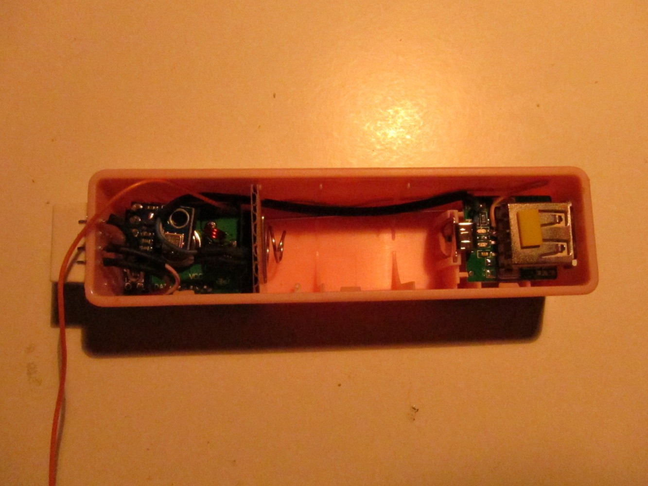
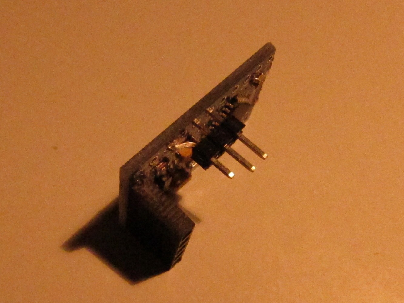
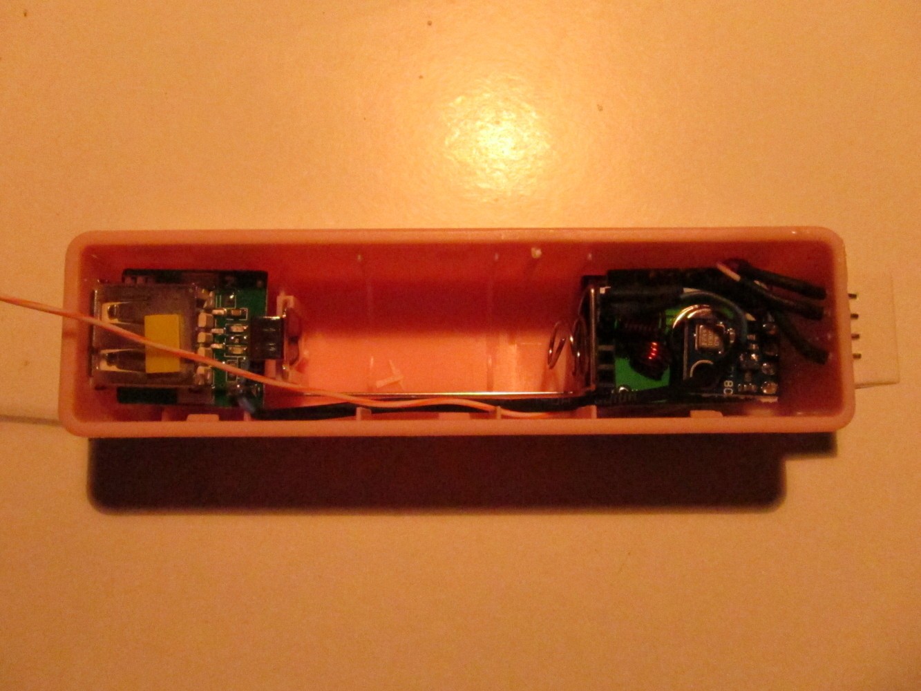
Here is an image of an earlier version of the sensor node:
Click here for a high-res picture
Here is a list of things to buy:
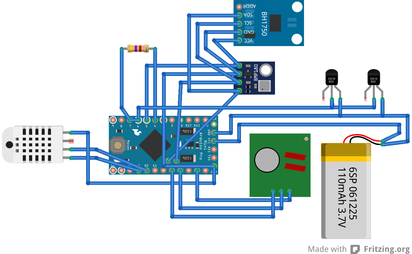
- Arduino Pro Mini 8MHz, 3.3V Ebay
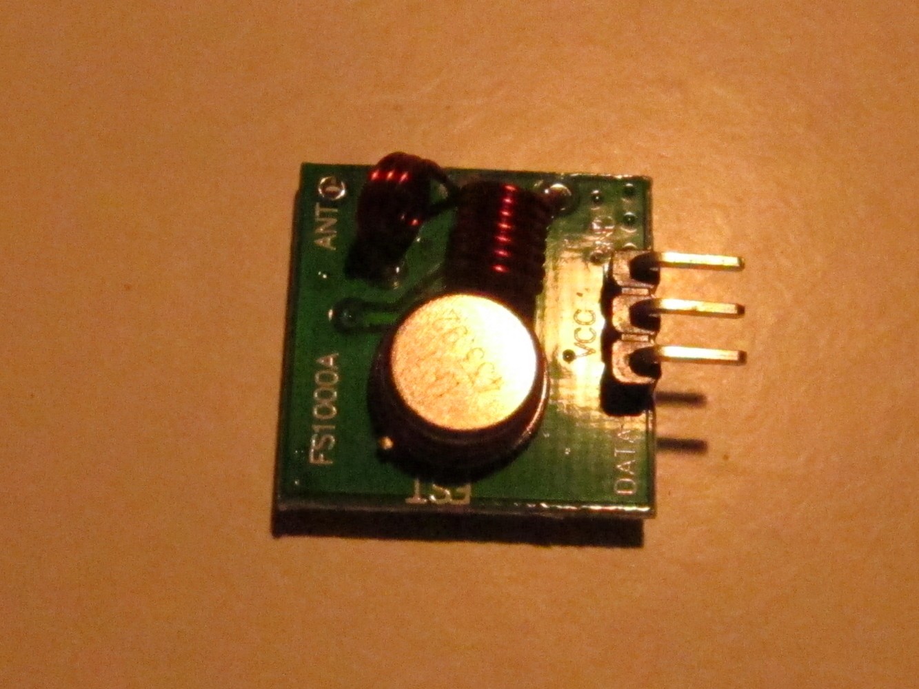
- 433 MHz sender module Ebay
- BMP180 pressure sensor Ebay
- DHT22 humidity sensor Ebay
- USB cell phone charger Ebay
- 16340 rechargeable battery Dealextreme
- Optional: USB plugs & DS18B20 tempereature sensors Ebay
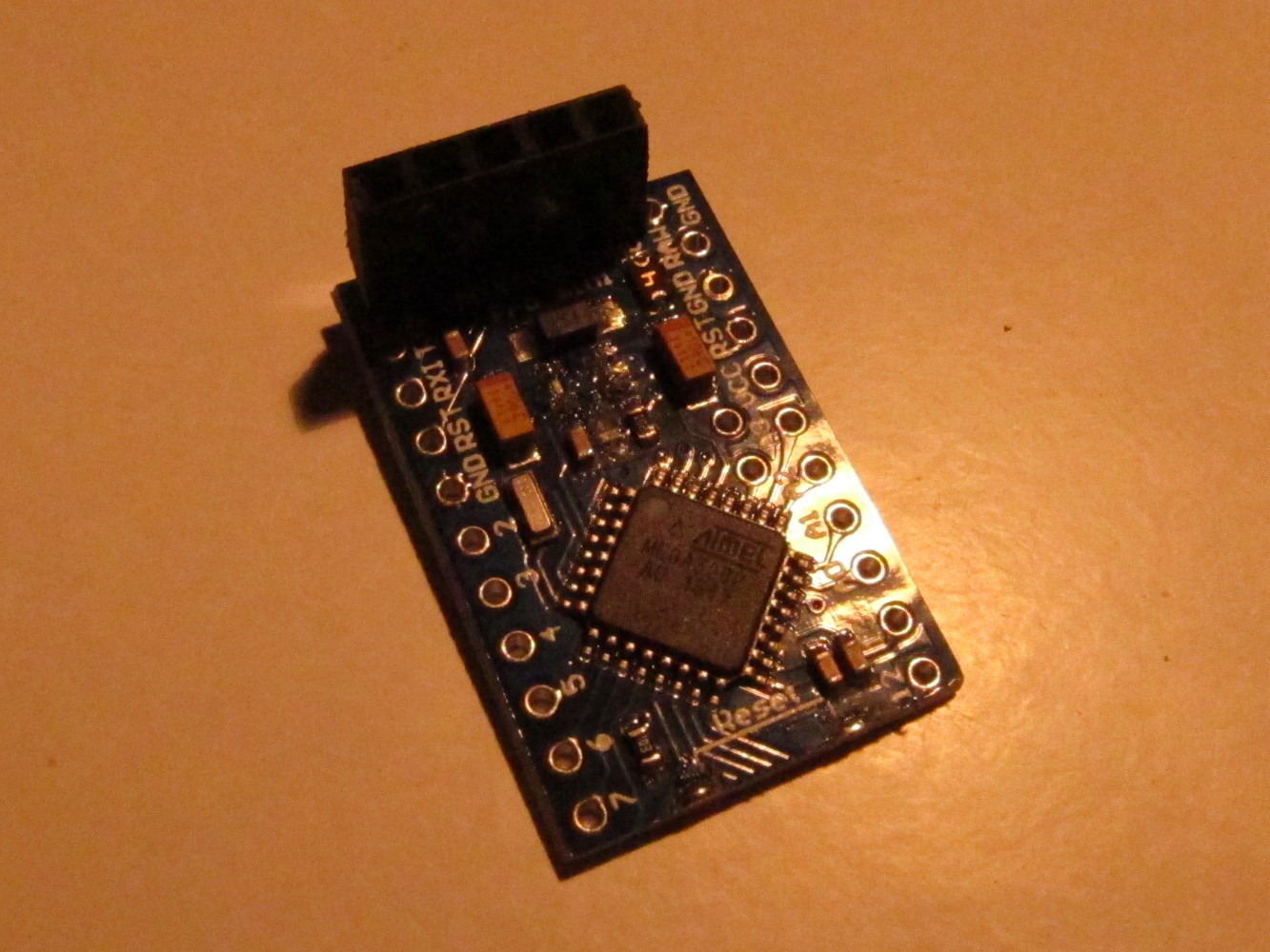
Note: The programming pins of my Arduino seem to have a different order.
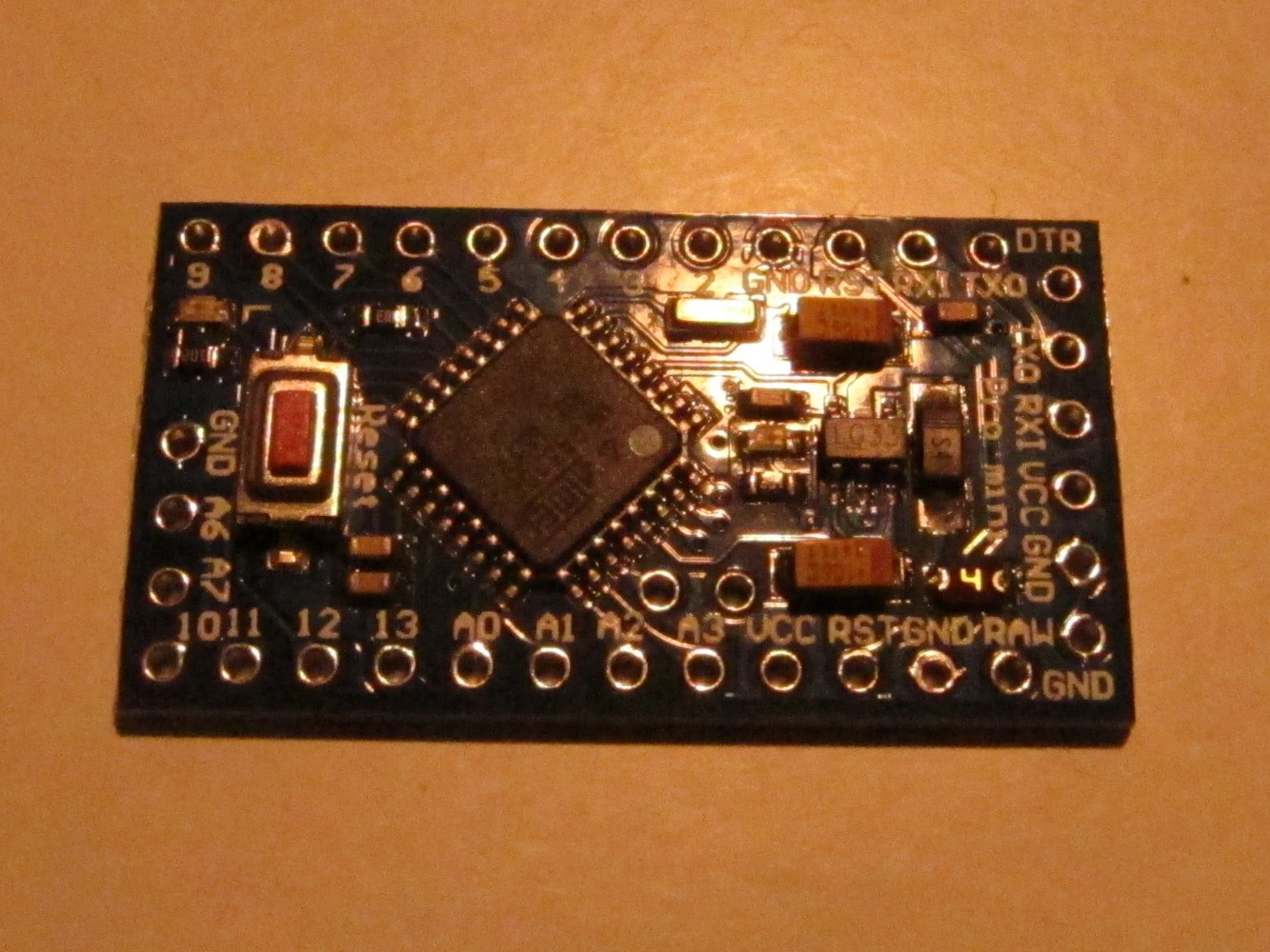
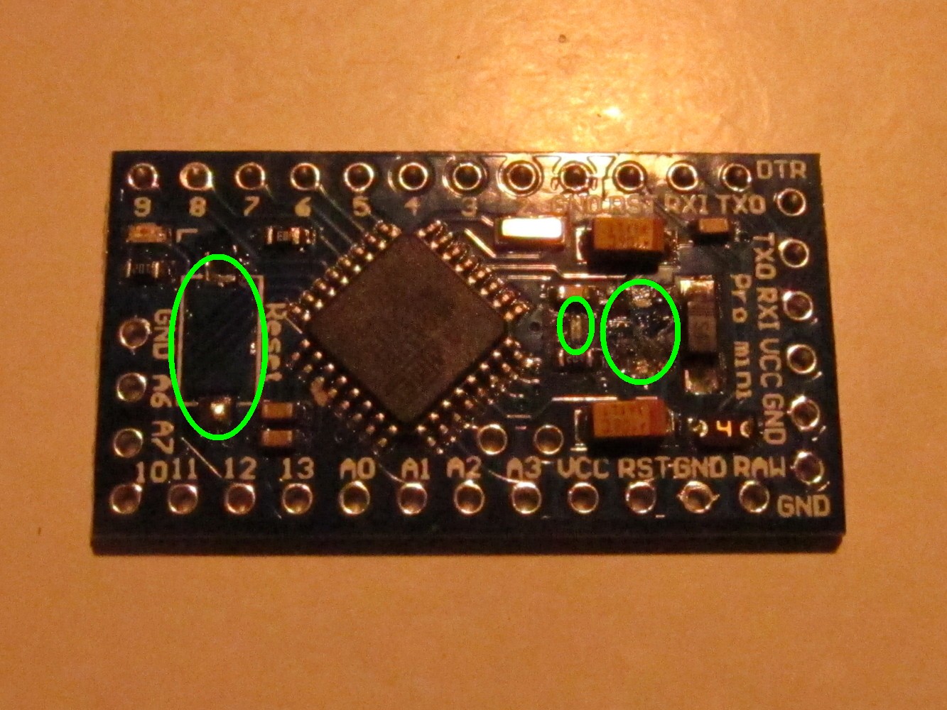
Here is the Arduino Pro Mini I used (left picture). First unsolder the reset button (right image, green circle on the left), the power indicator LED (circle in the middle) and the step-down converter on the right.
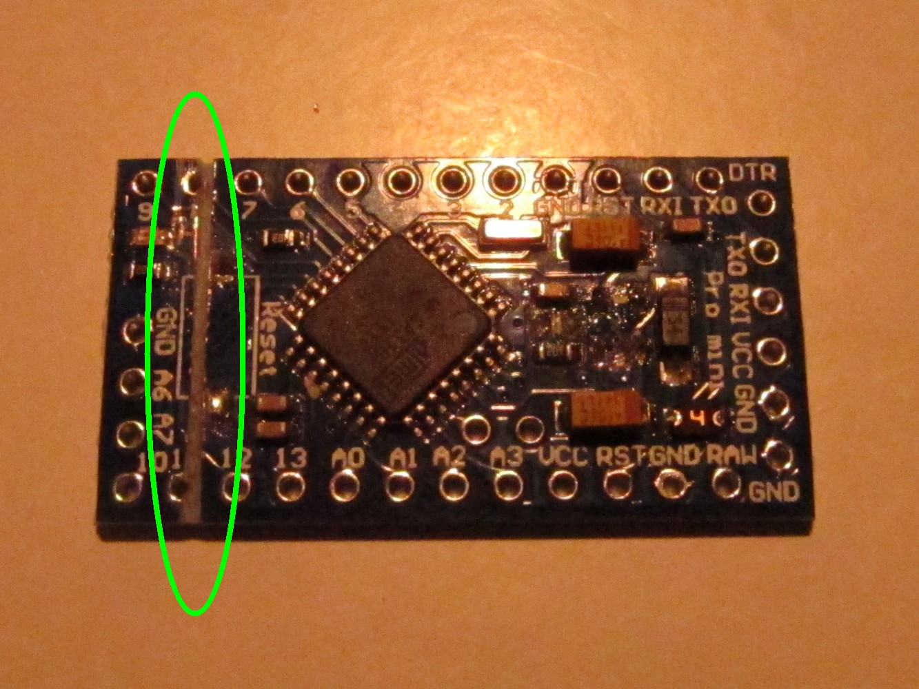
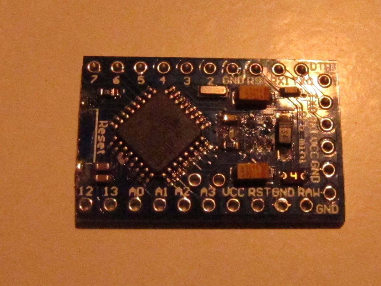
We have to shorten the Arduino so it fits together with the battery into the power bank case. So cut it with a saw between pin 11 and 12 so that pin 12 still remains usable as seen on the left picture. The result can be seen on the right.
The sender comes with pins that are not needed.
Add a female pin header to the Arduino to program it later. The free pin on the right is the second ground pin on the row.
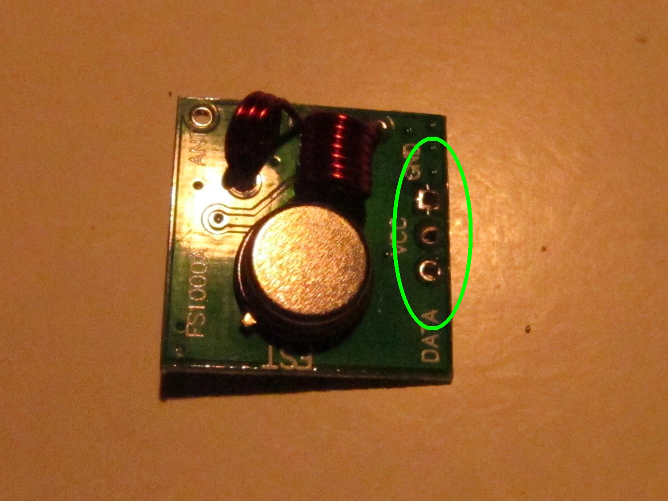
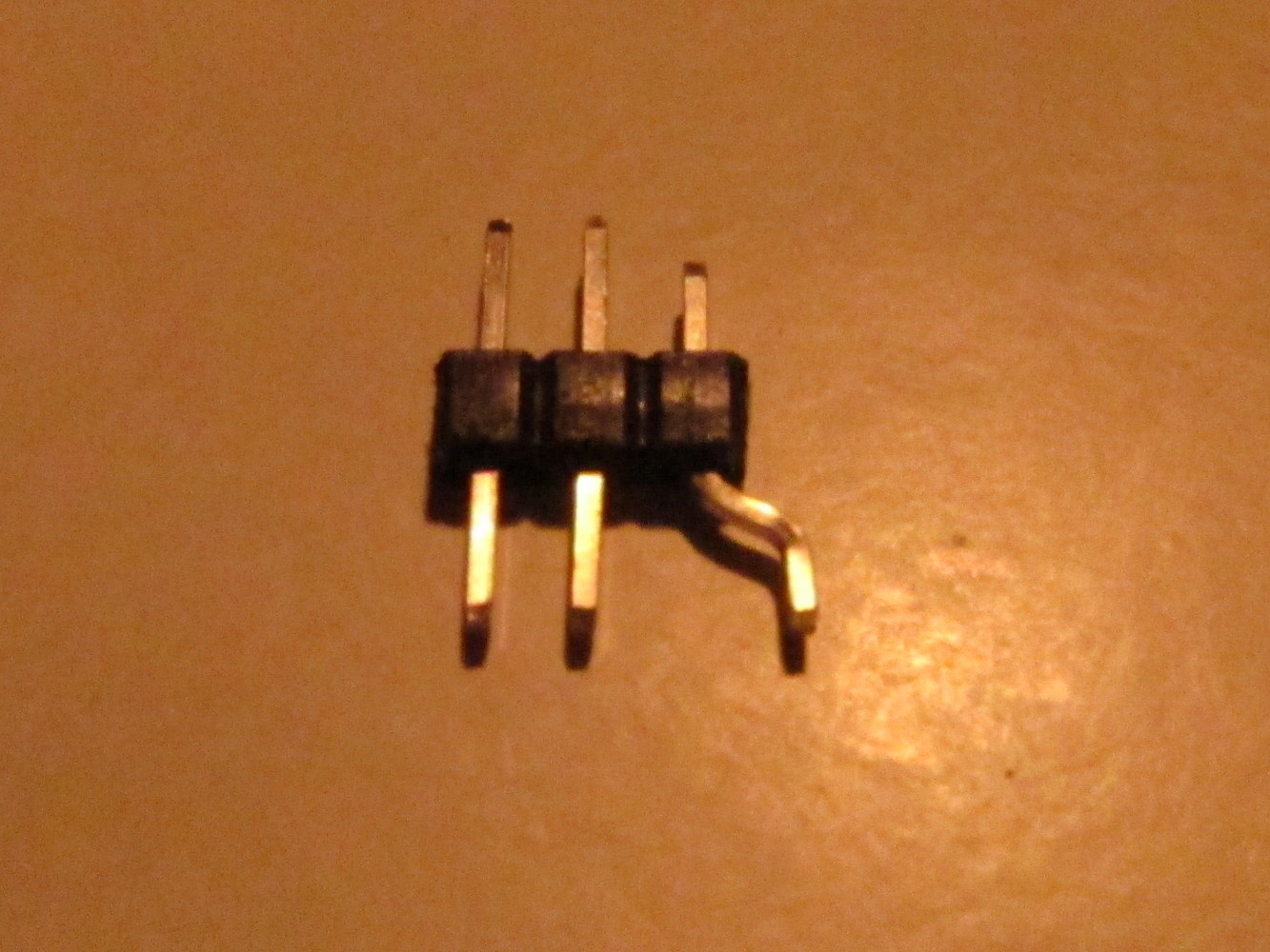
To connect the sender to the Arduino create an adapter as seen on the left picture. Solder it to GND, VCC and pin A3.
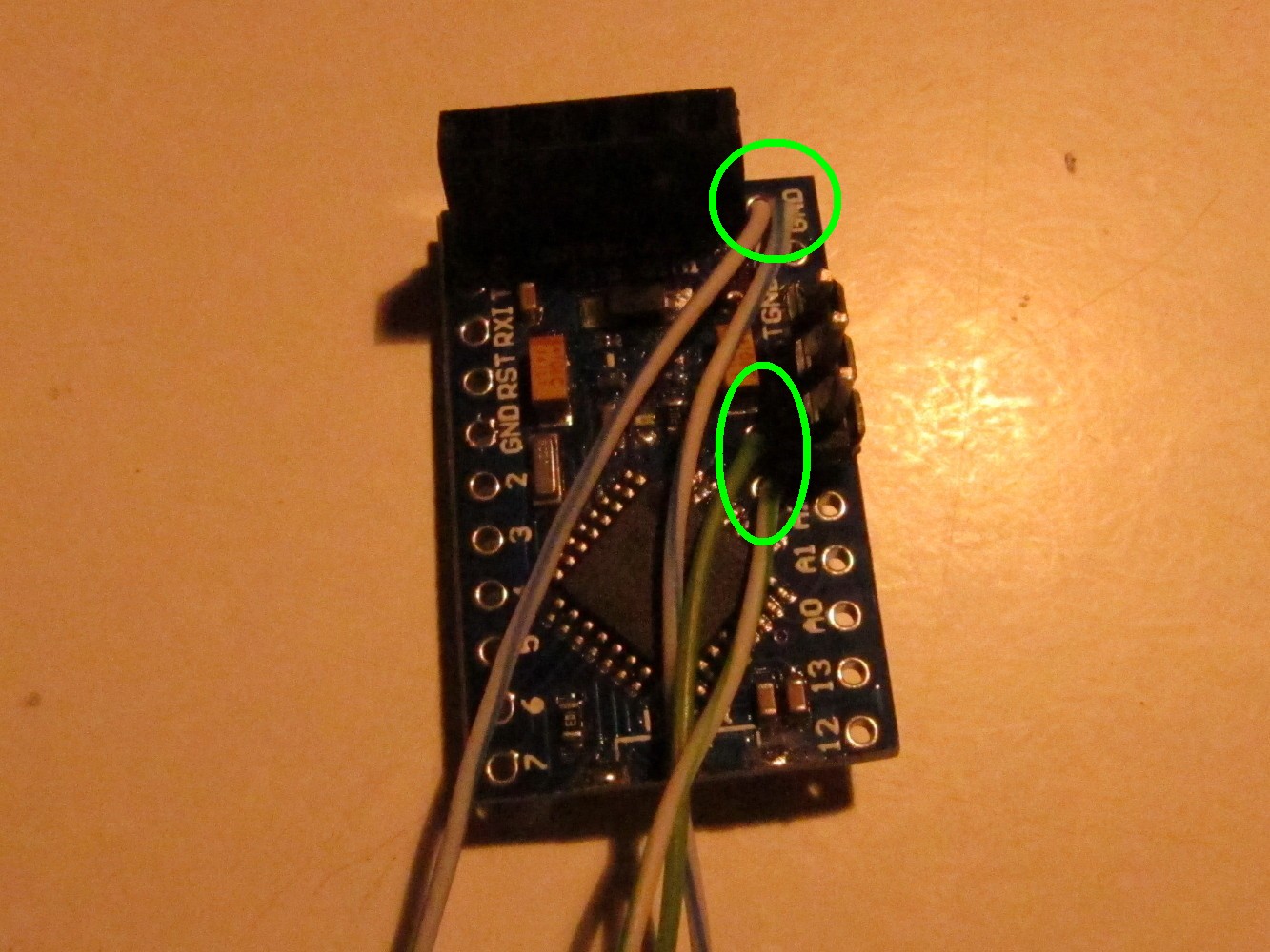
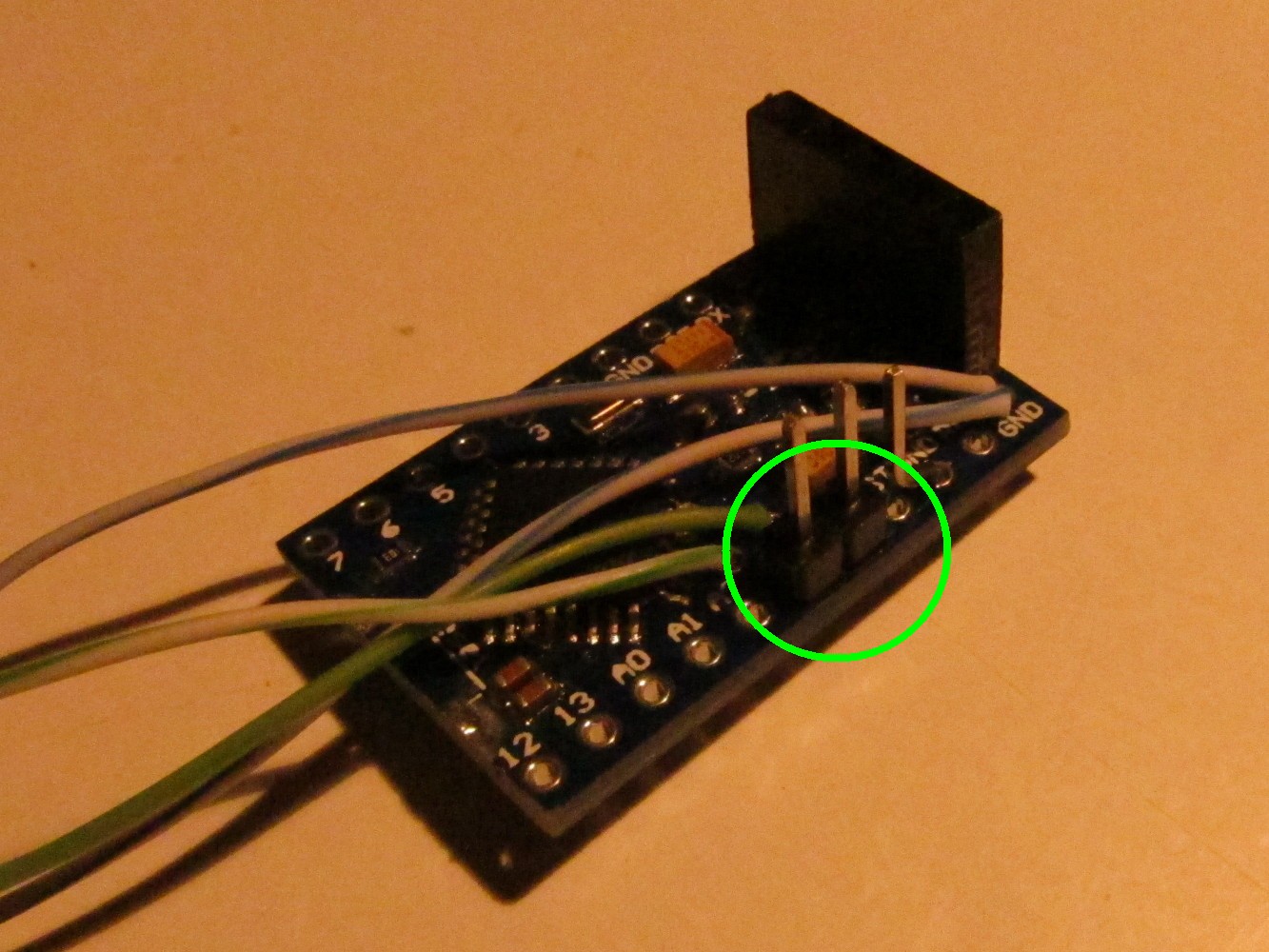
Solder two (half blue) cables to the free Arduino GND pin right of the programming headers (green circle at the top). Also add cables to Arduino pin A4 (half green wire) and Arduino A5 (green wire) (green circle in the middle). Remove the plastic connectors of the sender adapter and cut away one section. Then add it on the to straight pins and push it down to the Arduino board as seen on the right picture (green circle)
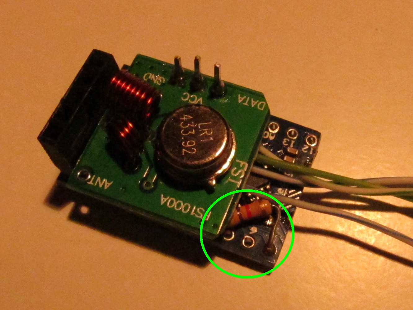
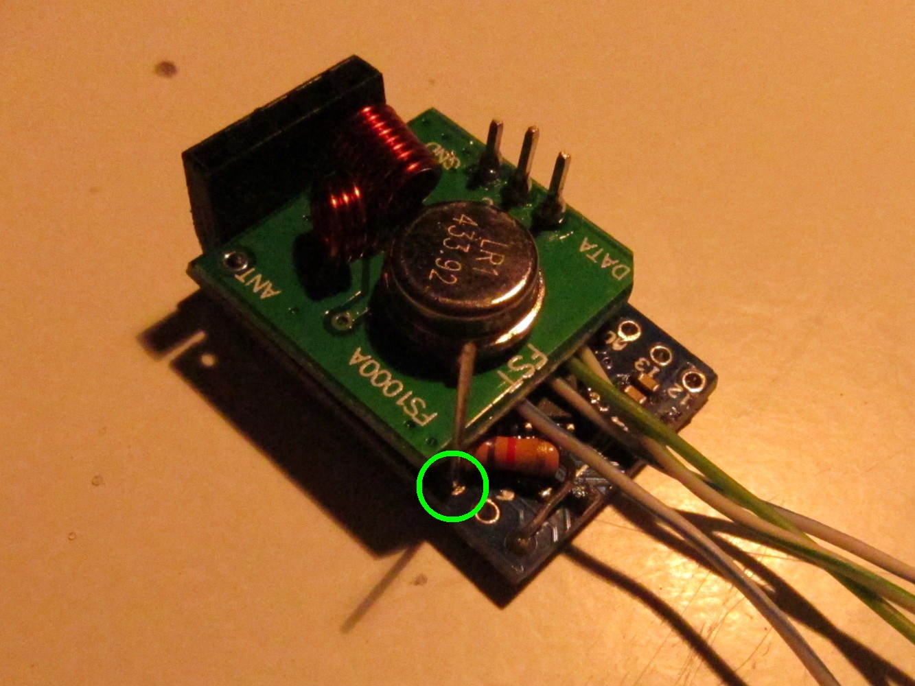
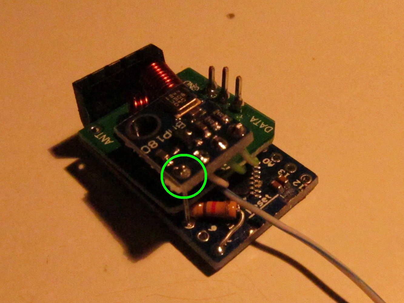
Solder a 4.7kOhm resistor to Arduino pin 4 and 7 as seen on the left picture (green circle). Then add the sender module on the top connected to the adapter as seen on the picture.
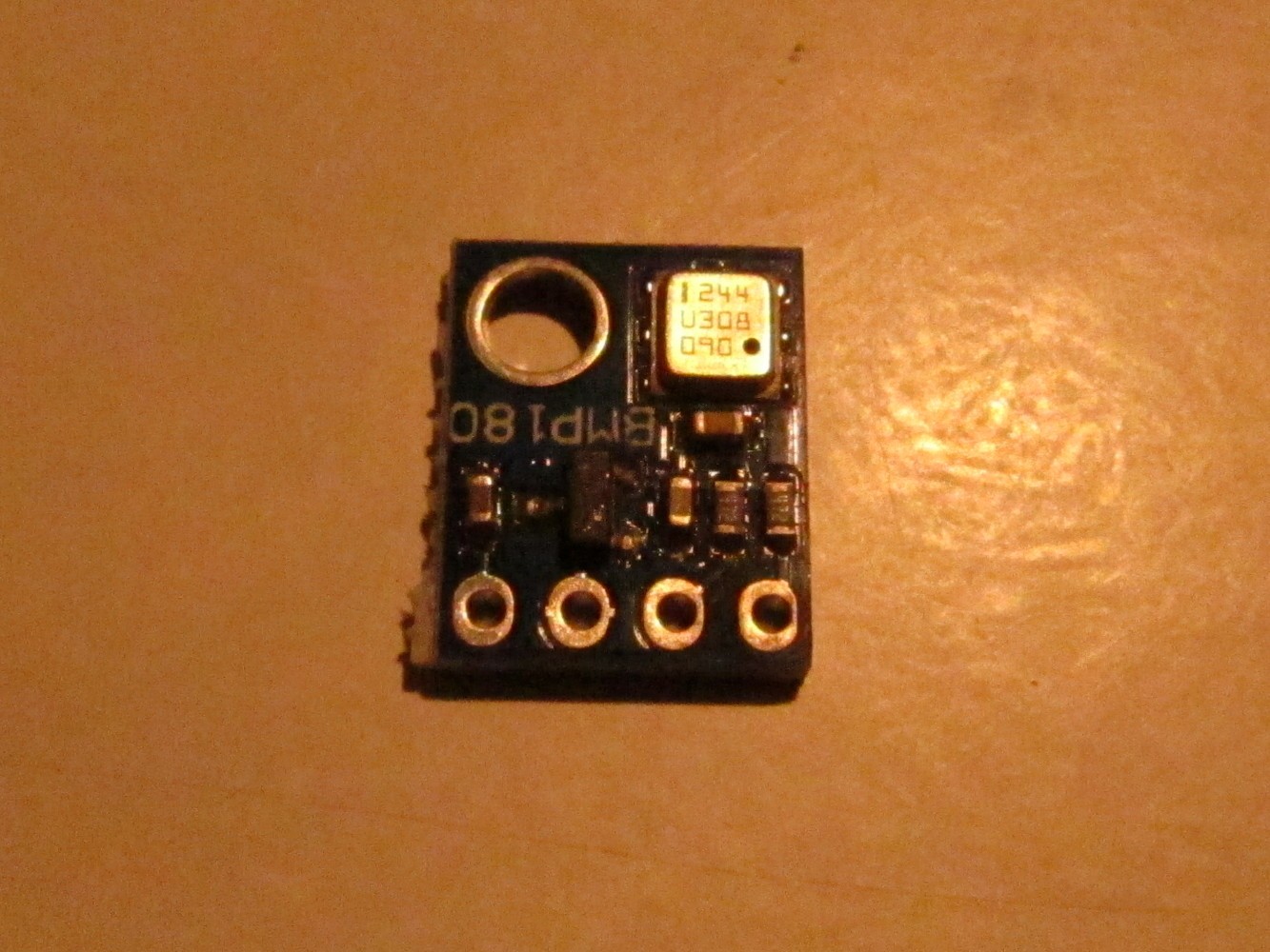
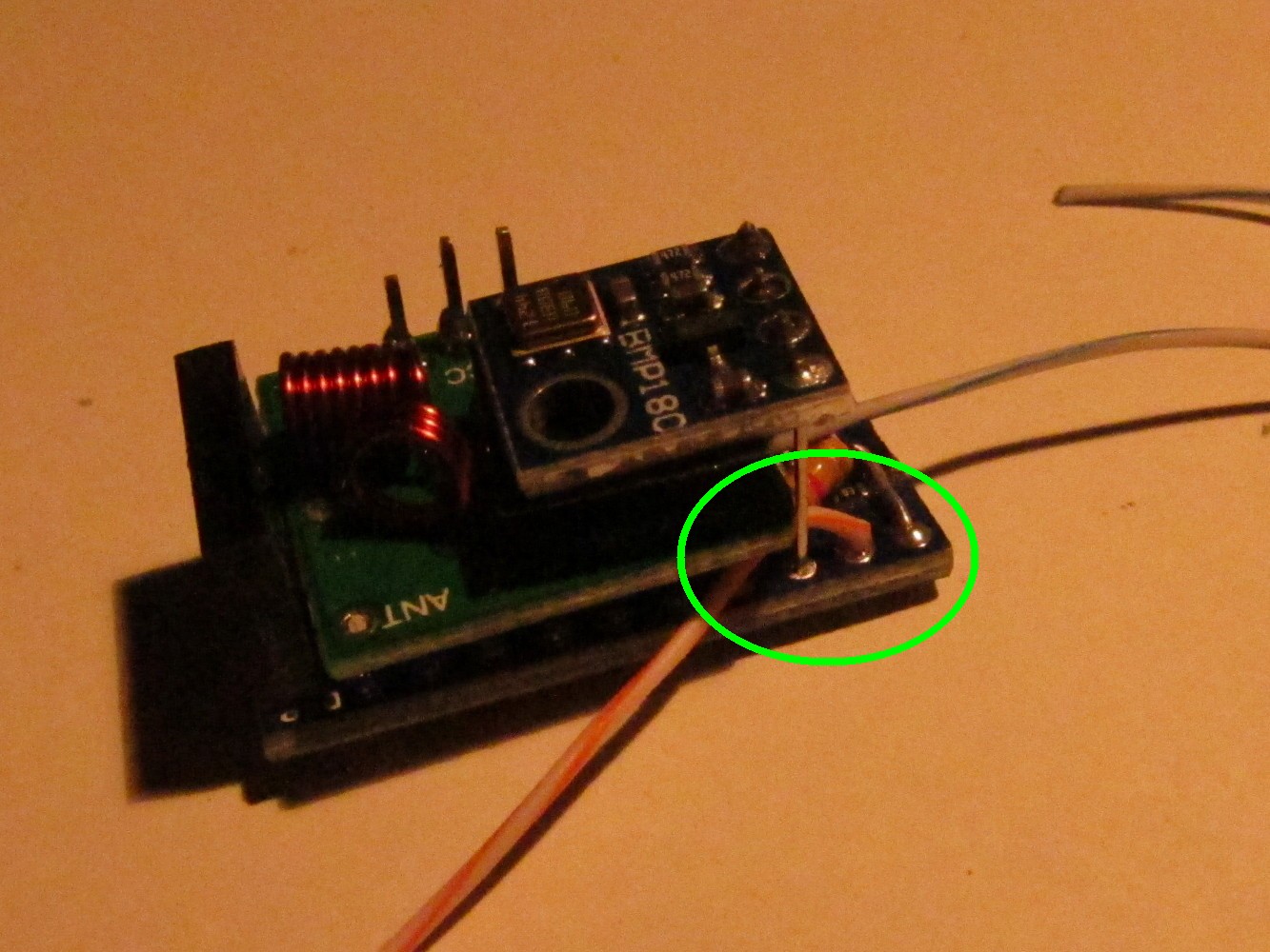
The VCC of the BMP180 sensor will be connected to Arduino pin 5. Therefore a long pin header is soldered to Arduino pin 5 as seen on the picture below (green circle).
Put a piece of tape on the bottom side of the BMP180 sensor as seen on the right image.
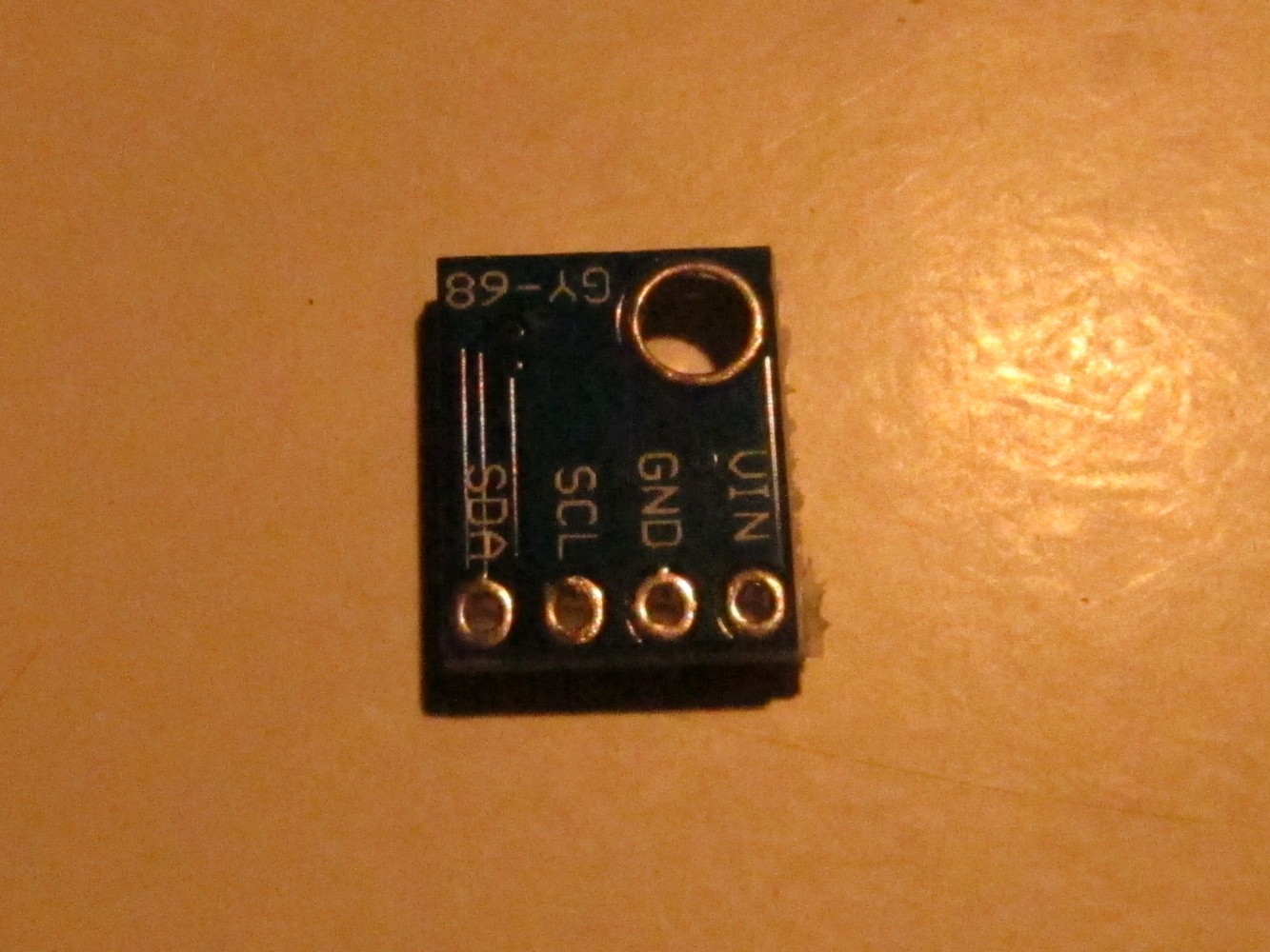
Cut the green wires and one of the blue ones as seen on the picture. Then solder the BMP180 as seen to the pin header (Arduino pin 5), GND (half blue wire), A5 (green wire) and A4 (half green wire).
Solder a long (10cm) wire to Arduino pin 6 as seen on the left picture. On the back side of the Arduino connect pin 6 and pin 7 as seen on the right picture (I forgot it when taking the pictures, that's why it shows a later step).
In general any case like this will work. I found there are small differences between the same looking cases on ebay. Especially when it comes to idle power consumption it might be interesting for this project. As a reference: A "good" case consumes about 0.025-0.050 mAh when idle without anything connected.
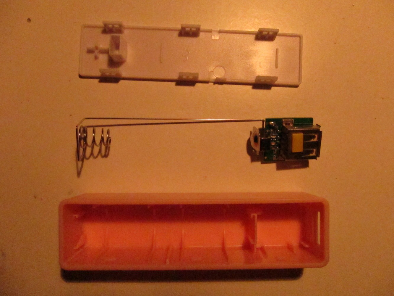
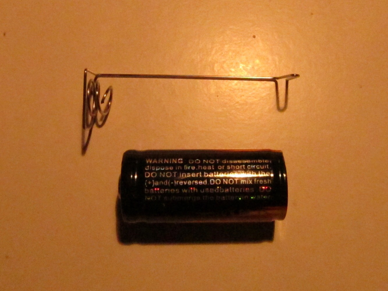
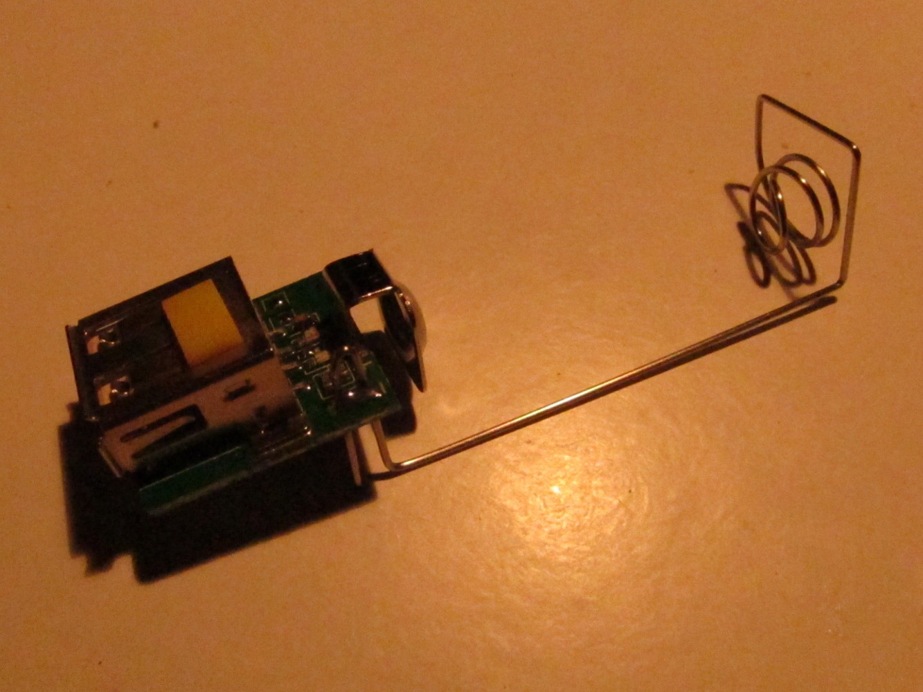
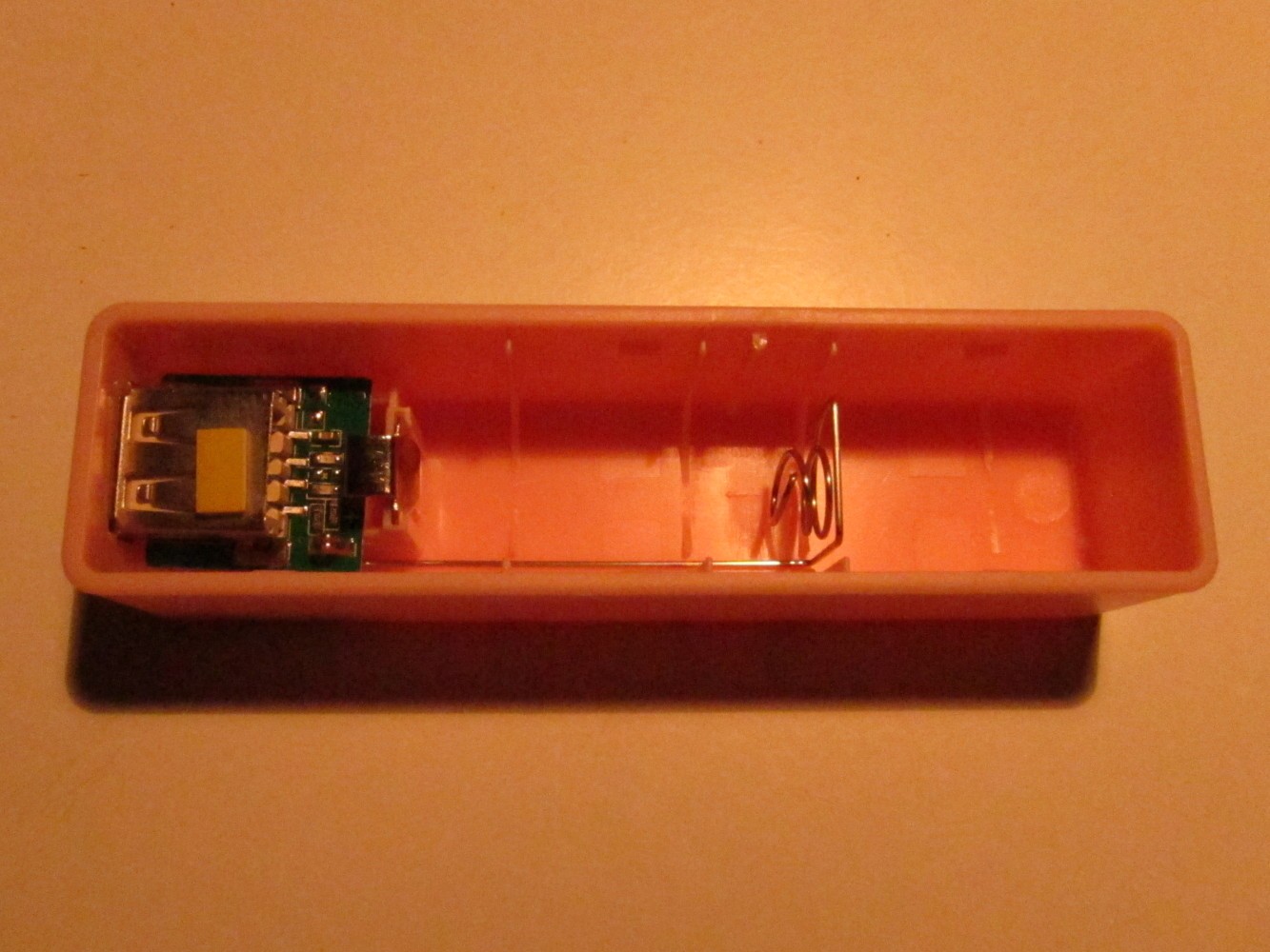
The battery holder has to be shortened to fit the 16340 battery. Unsolder it and shorten it as seen on the second picture. Then solder it again to the PCB of the charger (third picture). Check if the battery and the Arduino fits into the case. The result should look like on the most right picture.
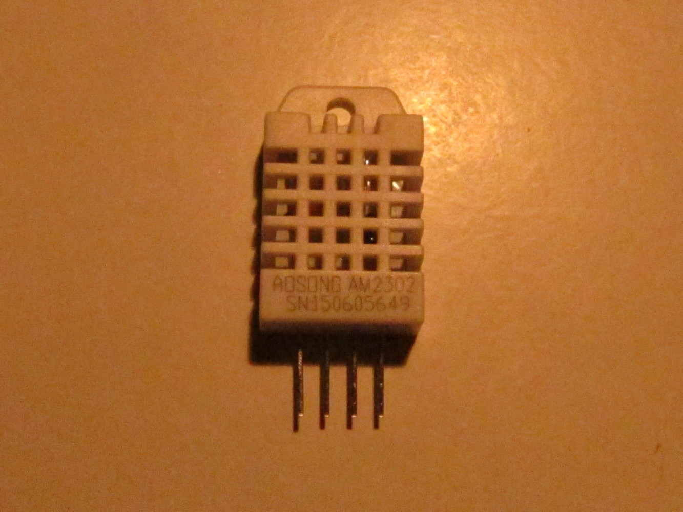
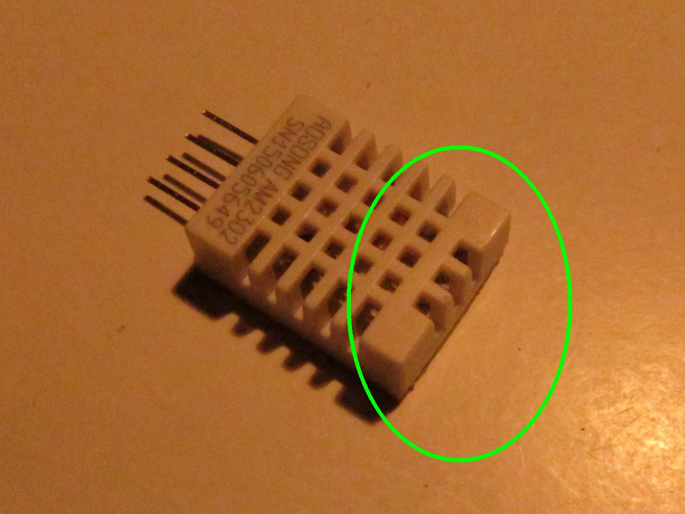
Cut off the upper part of the DTH22 sensor if you like. You could use the loop to fix the case somewhere but the sensor will not fit nicely onto the power bank case. The result is shown on the right picture.
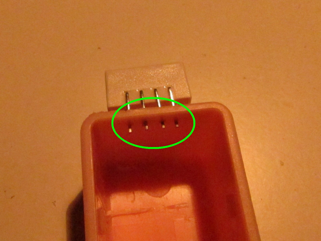
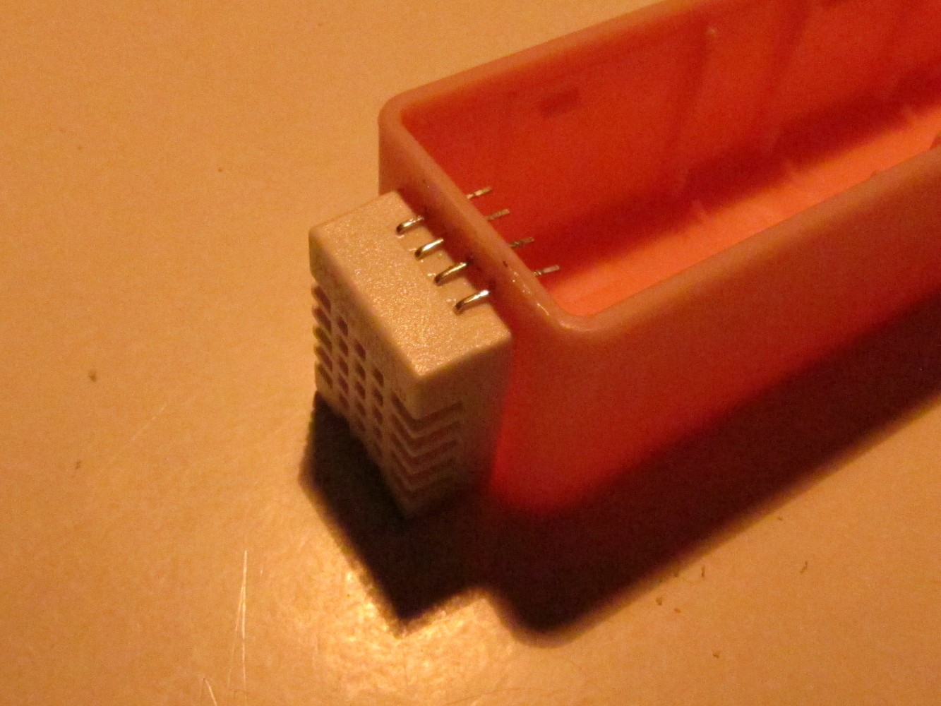
Pierce the pins of the DHT22 sensor through the case by heating them up with the soldering iron as seen on the left picture. Beware that there has to be enough space for the case cover. Finally, glue it to the case (right picture).
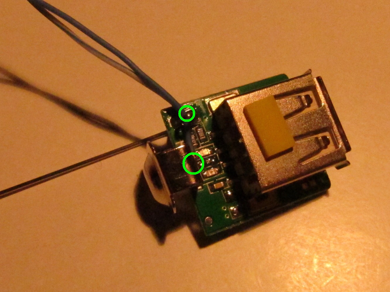
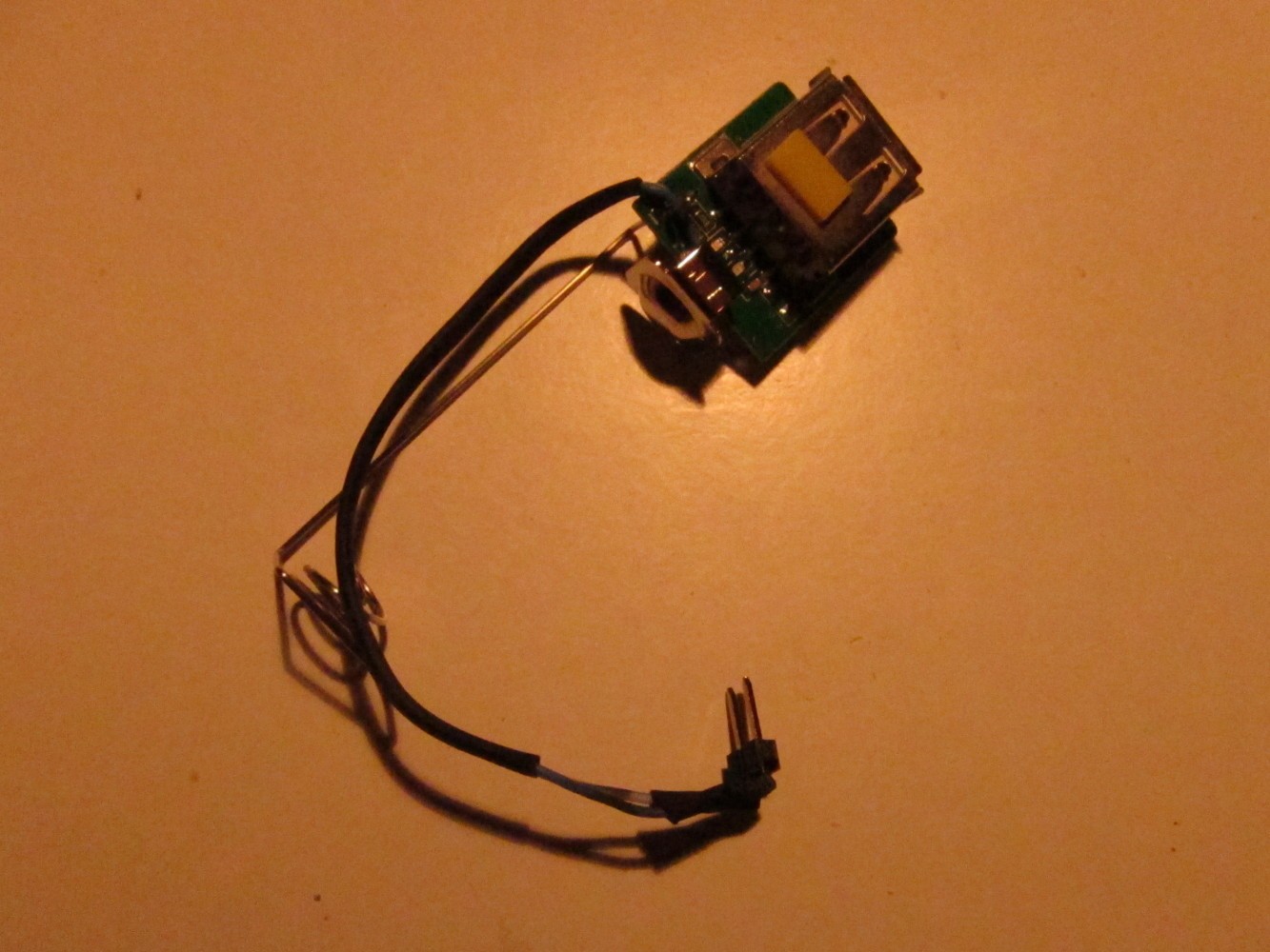
Solder a blue cable to the positive pole on the charger PCB and a half blue cable to the negative pole of the charger PCB as seen on the left picture. Cover it with shrinking tube and attach pin headers to it as seen on the right picture.
Solder a half brown cable to Arduino pin A0 (data) and a brown cable to Arduino pin 13 (VCC) as seen on the left picture. Then connect the DHT22 sensor with these cables and the half blue cable (GND) as seen on the right picture.
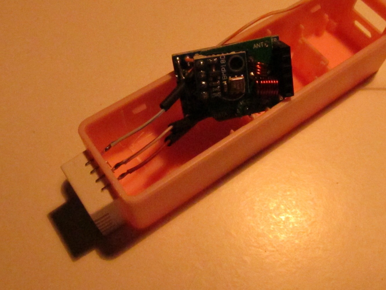
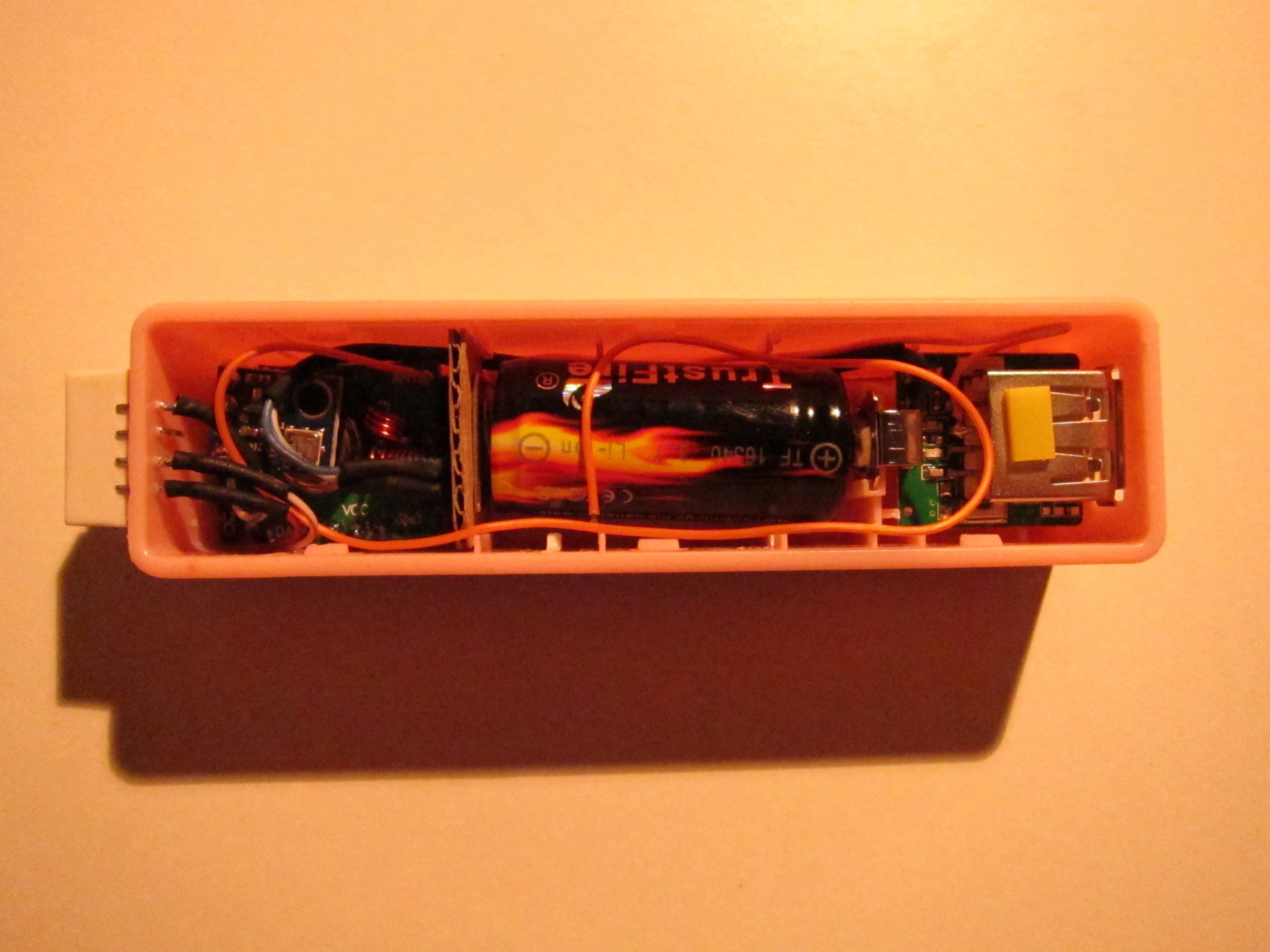
Fit everything into the power bank case as seen on the left picture and connect the power connector as seen on the right picture.
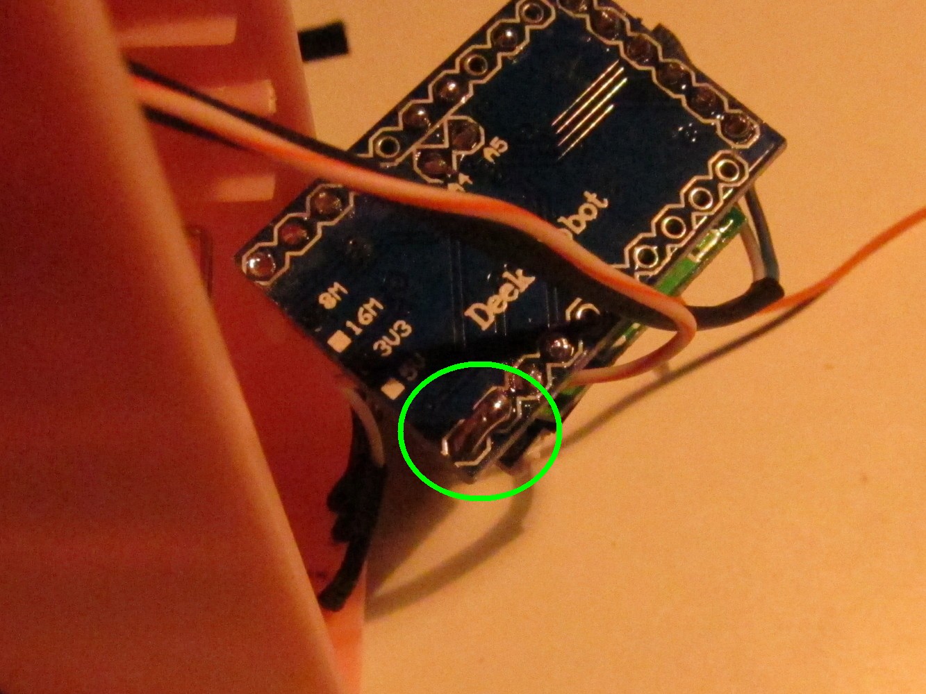
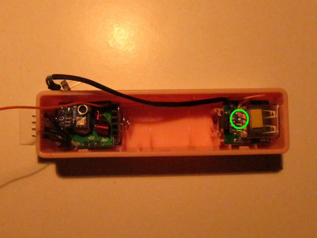
Solder the long, orange cable to the lower USB data connected (the one close to the USB ground).
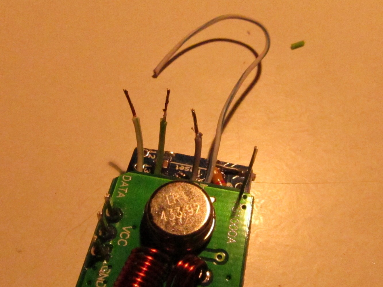
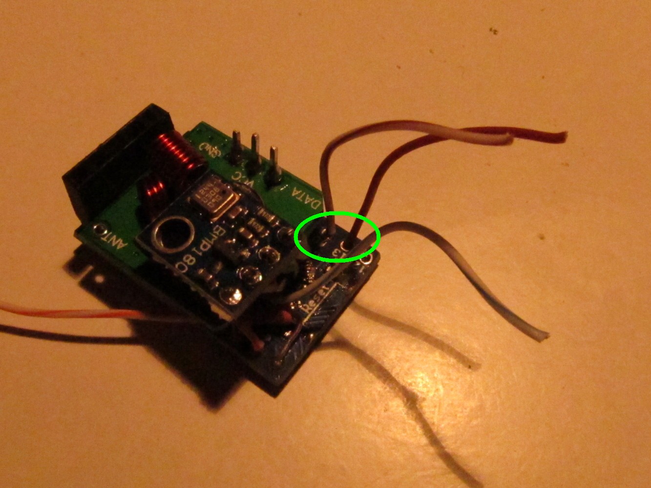
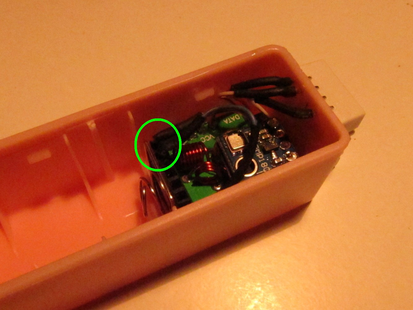
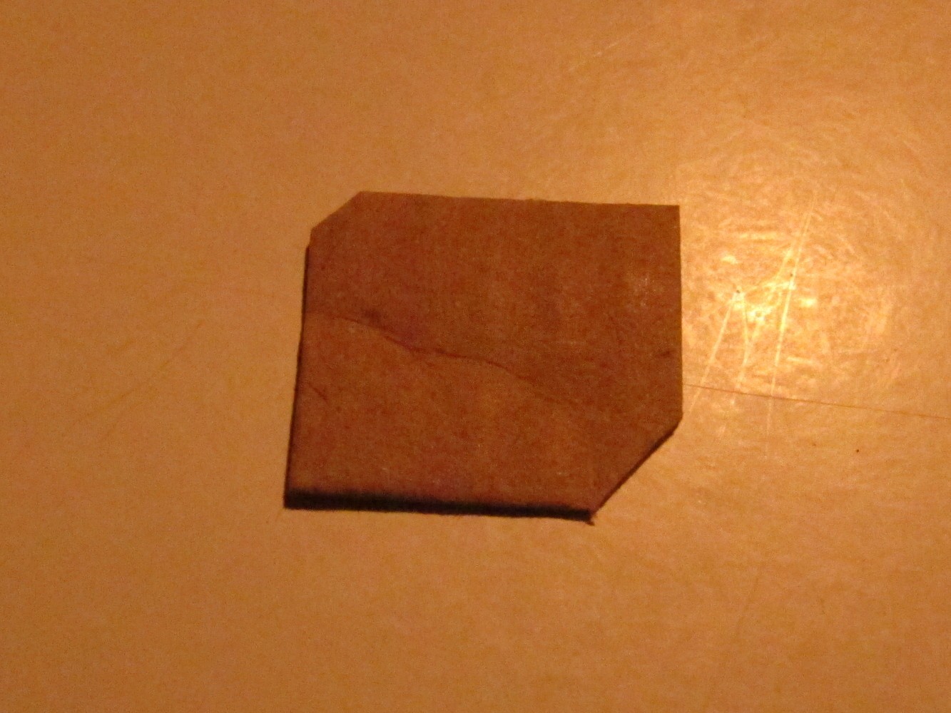
Cut a piece of paper as seen on the left picture and place it between the battery holder and the Arduino. Solder a 17.5cm long wire to the antenna pin of the 433MHz sender as seen on the right picture.
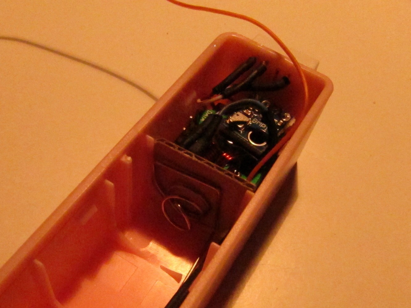
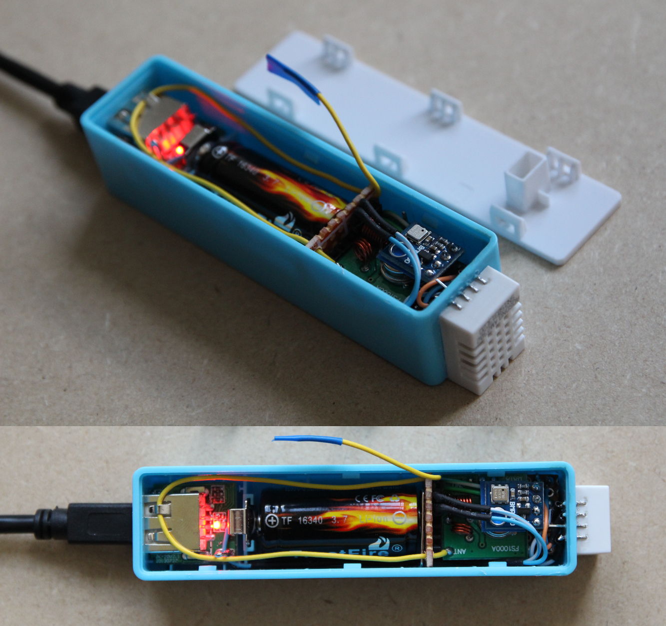
Assemble everything, it should now look like on the pictures below.