Advanced Lane Finding Project
The goals / steps of this project are the following:
- Compute the camera calibration matrix and distortion coefficients given a set of chessboard images.
- Apply a distortion correction to raw images.
- Use color transforms, gradients, etc., to create a thresholded binary image.
- Apply a perspective transform to rectify binary image ("birds-eye view").
- Detect lane pixels and fit to find the lane boundary.
- Determine the curvature of the lane and vehicle position with respect to center.
- Warp the detected lane boundaries back onto the original image.
- Output visual display of the lane boundaries and numerical estimation of lane curvature and vehicle position.
Rubric Points
###Here I will consider the rubric points individually and describe how I addressed each point in my implementation.
###Writeup / README
####1. Provide a Writeup / README that includes all the rubric points and how you addressed each one.
###Camera Calibration
####1. Briefly state how you computed the camera matrix and distortion coefficients. Provide an example of a distortion corrected calibration image.
The code for this step is contained in the IPython notebook located in "./Camera_Calibration.ipynb".
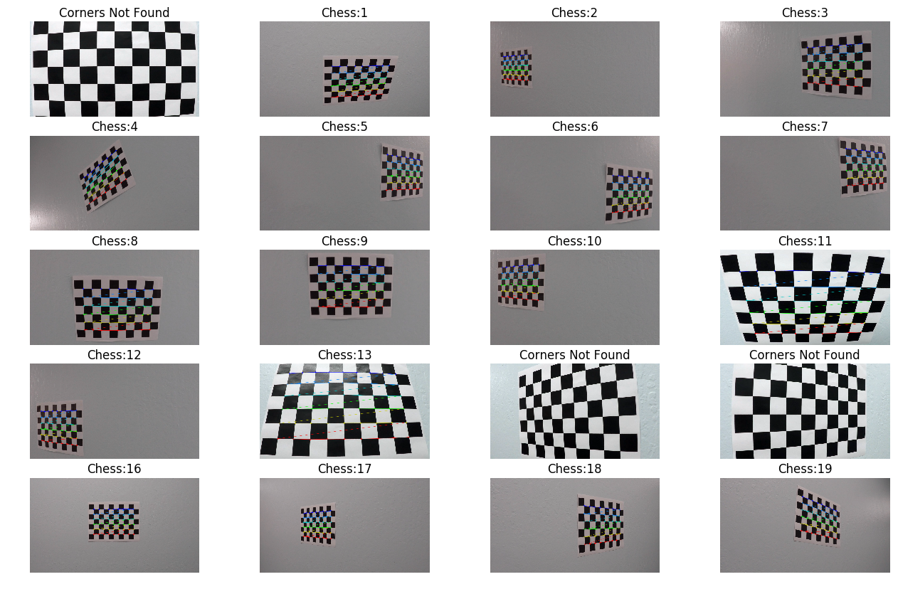
The main functions used for calibration are calibrateCamera and findChessboardCorners from the opencv package. A number of images of a chessboard taken from different angles were provided with the Udacity dataset that I have used to calibrate the camera.
The goal is to remove the distortion of the images that are cuased due mainly to projection of the 3D world (distance from the camera lens plane) view on a two dimensional camera plane. This distortion needs to be removed in order to get an accurate estimation of the objects and their relative positions when understanding the 3D world from a 2D camera image. This is achieved by computing a transformation matrix which will transform the distorted image into an undistorted image. To compute this matrix, we use a reference image of a chessboard photographed from various angles. findChessboardCorners function then uses this images to accurately compute the transformation matrix and distortion coefficients. The function undistort from opencv uses this matrix and the corresponding distortion coefficient to undistort the image.
Each of the frames of a video captured by a camera will be undistorted first before any further processing is applied.
Below are images for the two steps. The first the corners and then the undistorted images.
Undistorted Image on the right.
###Pipeline (single images)
The code for the following portion can be found in the "./MainProcessingScript.ipynb" jupyter notebook.
####1. Provide an example of a distortion-corrected image. To demonstrate this step, I will describe how I apply the distortion correction to one of the test images like this one:
The undistortion is little bit difficult to realize if you see the image on the right,but it is visible if we carefully look at the left edge of the image. In the camera grab, the white car is visible, but when undostorted (a.k.a when projected back onto the camera plane) the car is disappeared.
####2. Describe how (and identify where in your code) you used color transforms, gradients or other methods to create a thresholded binary image. Provide an example of a binary image result.
I have used a combination of color thresholding (to obtain the yellow and white lane markings), adaptive histogram equalization, and color space transformation to obtain the lane markers.
Having experimented a lot with different options (such as absolute sobel transforms, magniture sobel transforms and direction sobel transforms), I have ended up using only the magnitude sobel transforms on the S channel of the image after converting it into HLS color space.
Also, in the cell of the main processing file, where I have kept most of the utility functions (some of which I have used and some I didn't use at the end), I have ended up with 3 different pipeline functions, pipeline(), pipeline2(), and pipeline3(), of which I have ended up using the later two functions because it appeared to me that the combination of these two best able to capture the lanes. (I could have combined them into one funtion, but in the interest of time, I kept it as it they were).
However, before we did use the pipelines, I defined a portion of the image which best captured the lanes and the road in front of the camera and transformed it from a lateral view to a bird's eye view. It is described in the next questions. (I didn't change the order of the rubric questions, but in my script, I obtained the bird's eye view of the portion of the road of interest to us first).
The pictures below shows the result of applying Yellow mask on the bird's eye view image.

The pictures below shows the result of applying White mask on the bird's eye view image.

The pictures below shows the result of combining the two masks.
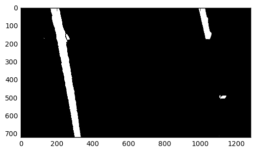
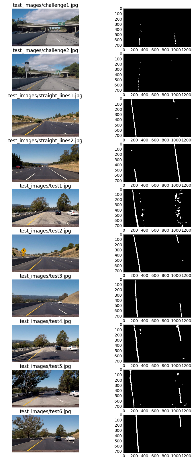
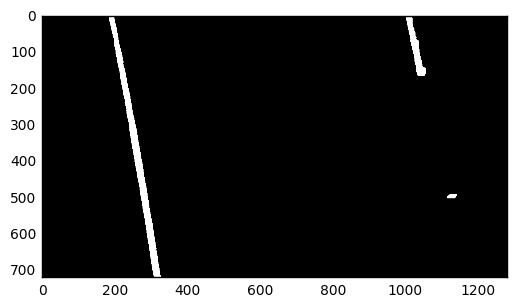
The pictures below shows the result of applying the pipeline2() on the test images (all the test images provided by Udacity along with couple of camera grabs obtained from the challenge video). pipeline2() outputs a combination of color masks on the image after converting to HSV color space and thresholded adaptive histogram equalization on the V channel of the image.
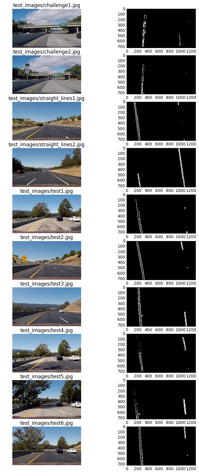
The pictures below shows the result of applying the pipeline3() on the test images (all the test images provided by Udacity along with couple of camera grabs obtained from the challenge video). pipeline3() outputs a combination of color masks on the image after converting to HSV color space and thresholded magnitude sobel transform on the S channel of the image after converting the warped image to HLS color space.
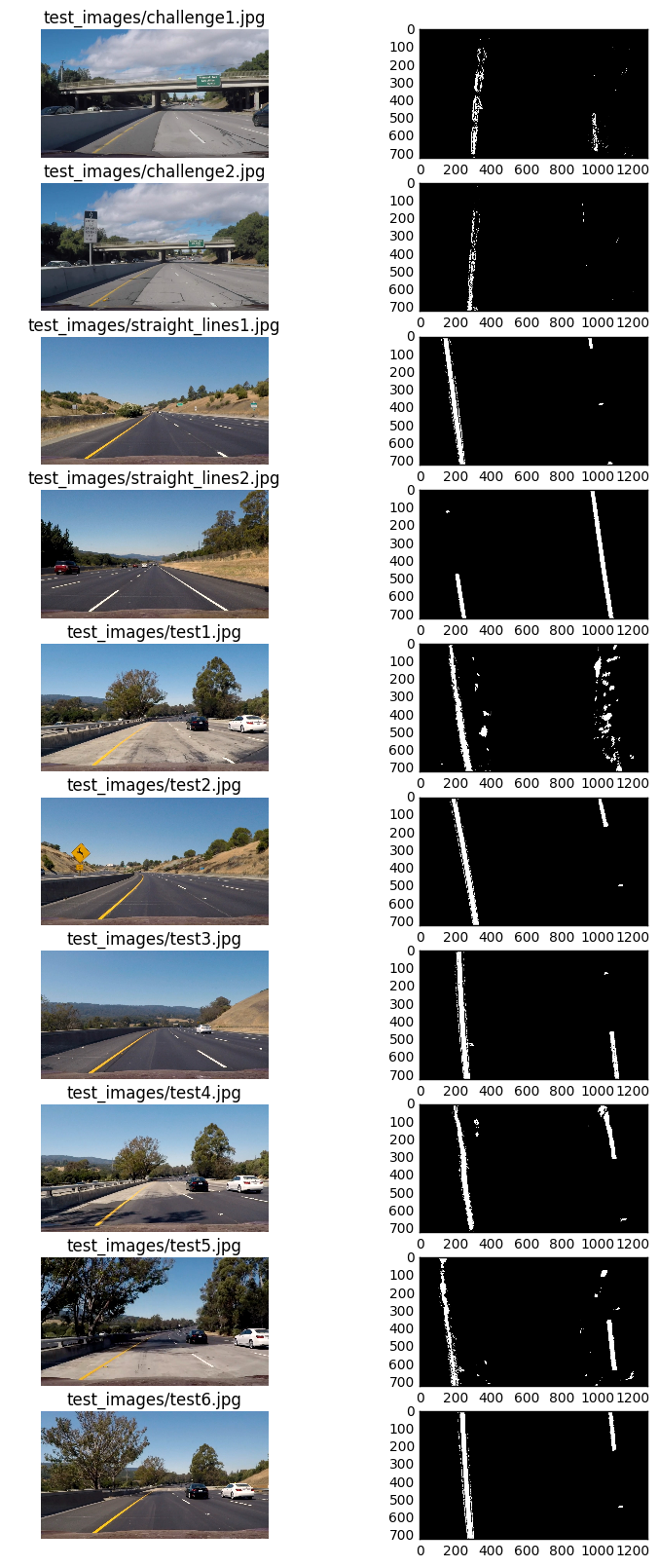
The picture below represents the combination of pipeline2() and pipeline3().
Note: In pipeline2 and pipeline3 above, I have also blacked out anything that generally falls outside the scope of the lanes to reduce unnecessary noise (and to reduce the error while fitting the polynomials). This could have done a bit better by utilizing the histogram image to figure out the zones to be blacked out, but the hardcoded range works great since the birds eye view image is allways consistent on where the lanes fall.
####3. Describe how (and identify where in your code) you performed a perspective transform and provide an example of a transformed image.
The code to obtain bird's eye view (othewise called Perspective Transform) appears with the cell heading Apply Perspective Transform to get a birds eye view of the lanes in front.
y_low = np.uint((img_shape[0]-50)*0.75)
y_high = np.uint(img_shape[0]-50)

Offset = np.uint(img_shape[1]//2)
tl_x = np.int(0.75*Offset)
tr_x = np.int(1.35*Offset)
bl_x = np.int(0.1*Offset)
br_x = np.int(1.9*Offset)

# points on the image to be transformed
src = np.float32([[tl_x,y_low],[tr_x,y_low],
                  [br_x,y_high],[bl_x,y_high]])

# points to which transformation takes place
dst = np.float32([[0,0],[img_shape[1],0],[img_shape[1],img_shape[0]]
                  ,[0,img_shape[0]]])
This resulted in the following source and destination points:
| Source | Destination |
|---|---|
| 480, 502 | 0, 0 |
| 864, 502 | 1280, 0 |
| 1216, 670 | 1280, 720 |
| 64, 670 | 0, 720 |
I have taken the points in the clockwise direction starting from top left in both the source and destination images.
####4. Describe how (and identify where in your code) you identified lane-line pixels and fit their positions with a polynomial?
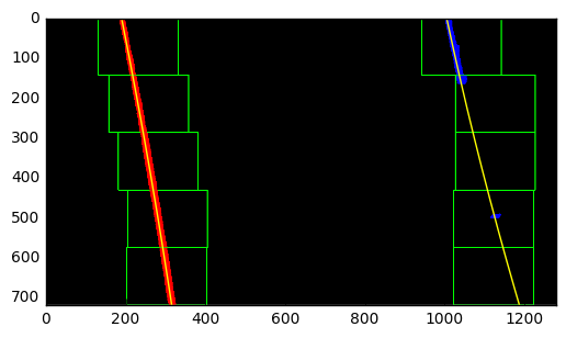
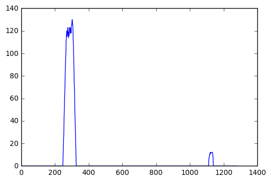
Once we obtained a binary image with white lane markings on it, we computed what is called a histogram of that binary image buy summing across each column of the image (since the white marks are pixels with value 1 and the rest are 0s), we otained two bumps, one on the left indicating the left lane and the one on the right, indicating the right lane. We then used numpy's argmax function to get the indices corresponding to the bumps on the left and right (we split up the histogram into two by dividing it in the middle ) and obtained the lanes.
The image is split up into 5 subsections, and each subsection we repeated the above proceedure and estimated the lanes before appending them back to collect the points needed for the entire image.
Once that is obtained, we fitted a 2nd degree polynomial through these points. Below is a picture of these steps.
####5. Describe how (and identify where in your code) you calculated the radius of curvature of the lane and the position of the vehicle with respect to center.
Once we obtained the left and right polynomials, calculating the Radius of Curvature is just applying the corresponding formula, adopted for the polynomials.
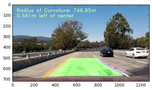
####6. Provide an example image of your result plotted back down onto the road such that the lane area is identified clearly.
After all the processing are applied and radius of curvature is calculated and written on the image, it is what I obtained.
###Pipeline (video)
####1. Provide a link to your final video output. Your pipeline should perform reasonably well on the entire project video (wobbly lines are ok but no catastrophic failures that would cause the car to drive off the road!).
Here's a link to my video result
###Discussion
####1. Briefly discuss any problems / issues you faced in your implementation of this project. Where will your pipeline likely fail? What could you do to make it more robust?
Here I'll talk about the approach I took, what techniques I used, what worked and why, where the pipeline might fail and how I might improve it if I were going to pursue this project further.
As I have described above, I have built a pipeline for the processing based on the test images provided, as well as some of the grabs from the challenge videos provided. I noticed that the pipeline works pretty well. Although, when the picture is very darks (such as underneath a bridge), it failed to identify any lines. Also, when the background is too whitish (such as on a concrete bridge), the right lane wobble slightly, not too much that the car will drive off the road).
I have tried to experiment a lot and feel that there must be some other way, either some technique or some different combination of the thresholds etc, could eliminate the problems above. Also, I faced some problem with previous_polyfit() function that I used from the lessons. Due to interst of time, I ended up using the initial_polymask() for each of the frame. Once I get some time, I plan to work on removing these problems wit my code.
