This project provides a script and GUI that makes a PCB layout, created in either OrCAD or Allgero much easier to read and review. It is also great for hardware debugging. Note that the OrCAD and Allegro PCB layout tools are both sold by Cadence and use interchangeable file formats.
- It has NO effect on the fabrication and manufacturing layers (eg ASSEMBLY, SILKSCREEN)
- orients, centers, and automatically sizes the REFDES's and pin designations on the TOP DISPLAY layer
- orients, changes to forward direction, centers, and automatically sizes the REFDES's and pin designations on the BOTTOM DISPLAY layer
- gives easy control of the colors used for the display layer via a set of three +/- buttons for Hue, Saturation, and Lightness (HSL).
The script is written in Cadence SKILL, which is a variant of Lisp.
- Download the zip file for this github repositiory by clicking the
Codebutton above and selectingDownload ZIP.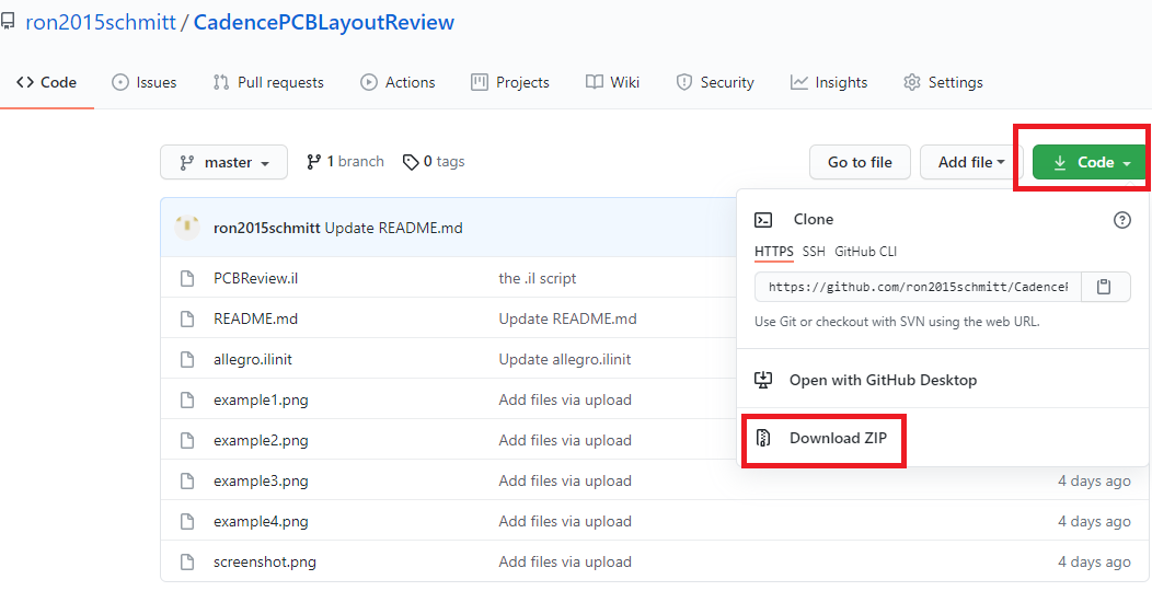
- Unzip the downloaded
.zipfile to any location that you like. - The Skill script
PCBReview.ilis the only file that you need. This script will run from any folder. Of course, if your installation has a skill folder, e.gC:\Cadence\[VERSION]\setup\skill, you can copy the filePCBReview.ilthere.

- Open the OrCAD (or allegro) layout tool and open the layout that you wish to view / edit.
- Go to to
Commandwindow inside OrCAD (or allegro) layout and type
skill
load "[path]/PCBReview.il"
pcbreview
where [path] is the full path to the folder that you saved the PCBReview.il file to. Note that in your path you MUST use forward slashes ('/') and NOT backslahses ('\'). The use of double quotes surrounding the "[path]/filename" is also required.
- The modifications to the DISPLAY layers described above will take place.
- Afterward completion, the following popup window will appear which allows control of the colors and other display features.

This step is optional.
- Place the load command above in your
allegro.ilinitinitialization file for OrCAD Layout. This is typically located in a folder namedPCBENV\orpcbenv\. or - Merge the contents of
allegro.ilinitfrom this repository with the yourallegro.ilinitinitialization file for OrCAD Layout. This file loads all the scripts in theC:\Cadence\setup\skillfolder during initialization of the OrCAD Layout application. (allegro.ilinitis the initialization file for OrCAD Layout.) Be sure to changeC:\Cadence\setup\skillto the path where your skill scripts reside.


