This repository contains the source files for keyboard designs and keyboard firmware.
Kicad source files are in pcb.
Plotted gerber files can be found under the GitHub repository's releases.
| Designation | Summary/Keywords | Image |
|---|---|---|
| X-1 | 36-key (2x3x5+3), split, column-staggered, MX/choc, sub-100x100, per-key RGB LED, ARM | 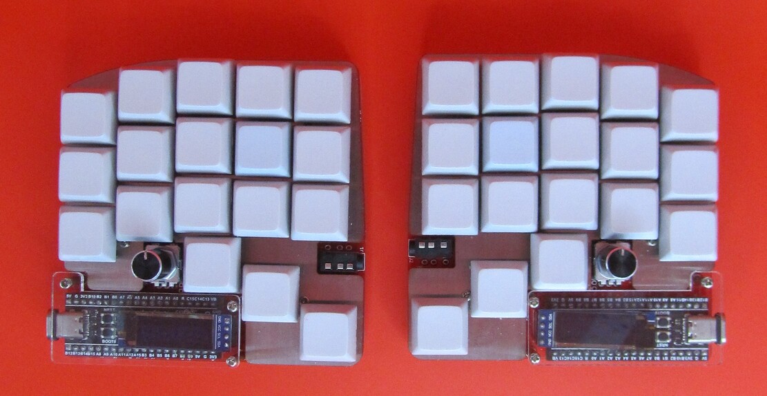 |
| X-2 | 60-key (5x12), un-split, ortholinear, MX/choc, GH60-compatible, "show the components", ARM | 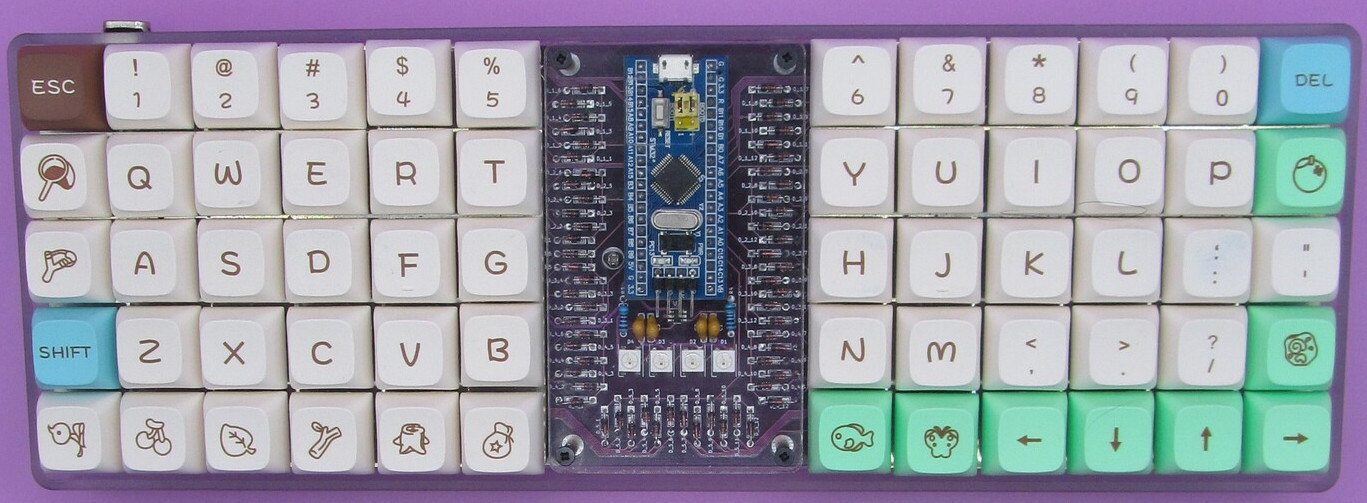 |
| X-2 HSRGB | 60-key (5x12), un-split, ortholinear, MX/choc, GH60-compatible, "show the components", HotSwap, per-key RGB, ARM | 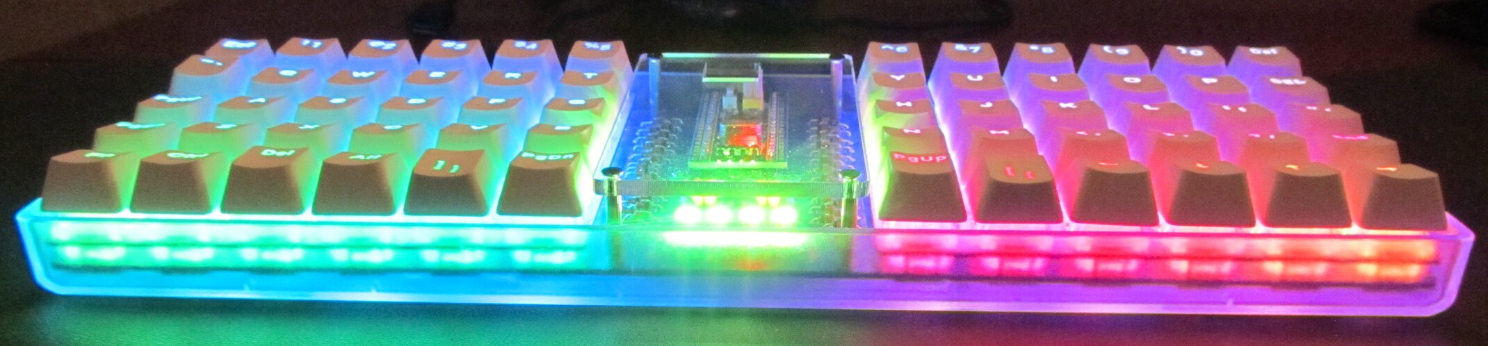 |
| PyKey40 Lite | Planck-MIT (4x12, 1x2U), ortholinear, MX, BM40/JJ40-compatible, PCBA, no frills, ARM | |
| PyKey40 HSRGB | Planck-MIT (4x12, 1x2U), ortholinear, MX, BM40/JJ40-compatible, PCBA, HotSwap, per-key RGB LED, ARM | 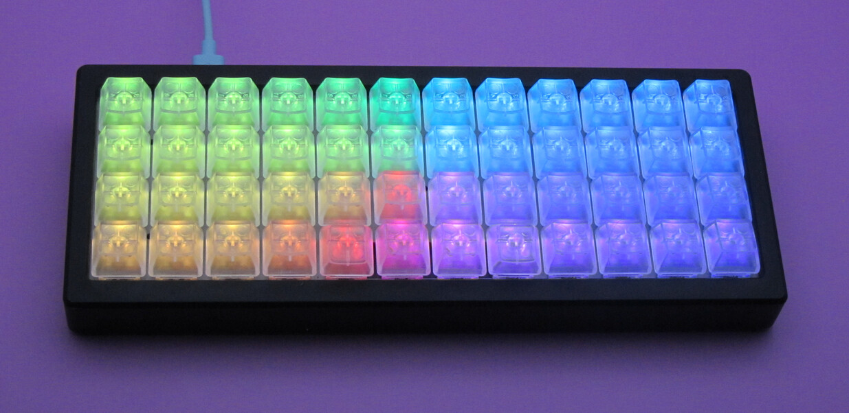 |
| Pico42 | 42-key ortholinear, MX/choc, BM40/JJ40-compatible, no frills, ARM | 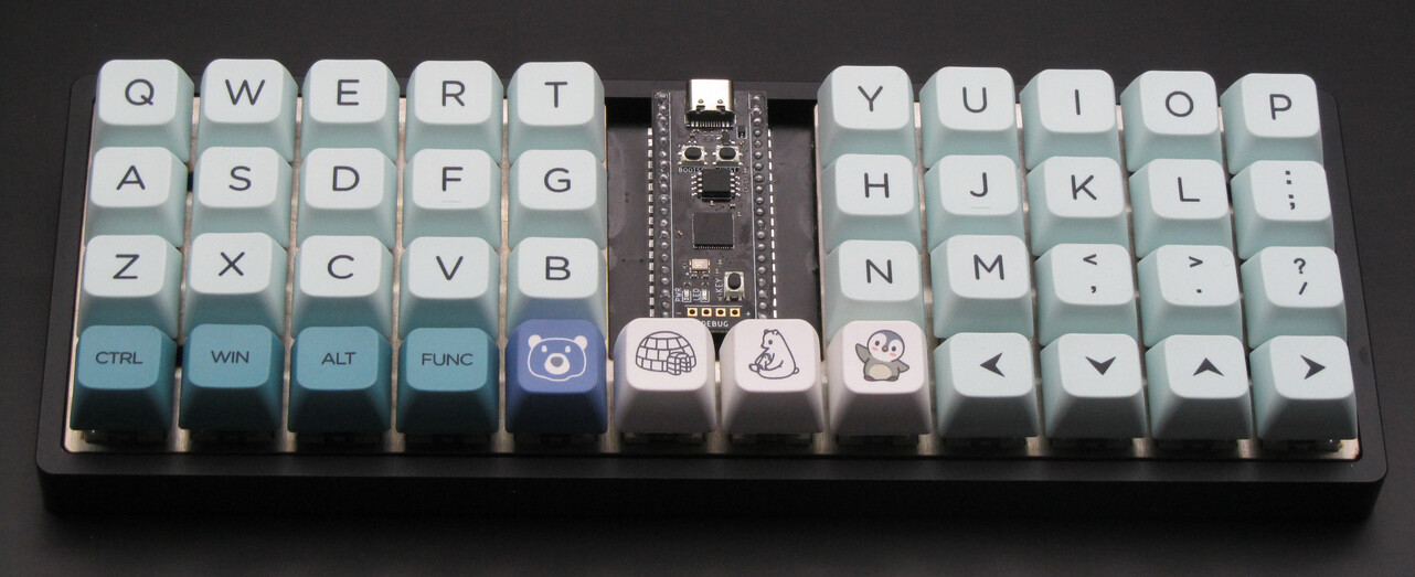 |
| CH552-44 | 44-key ortholinear, MX, BM40/JJ40-compatible, no frills | 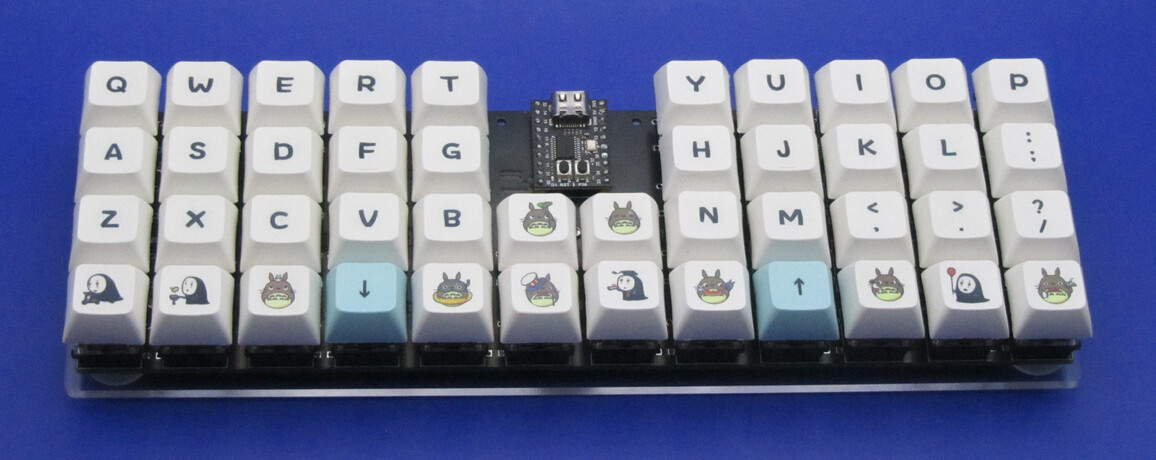 |
| CH552-48 | 48-key ortholinear (4x12), MX, BM40/JJ40-compatible, no frills | 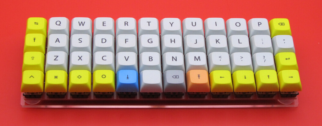 |
| CH552-48-LPR | 48-key ortholinear (4x12), low profile redragon, no frills | 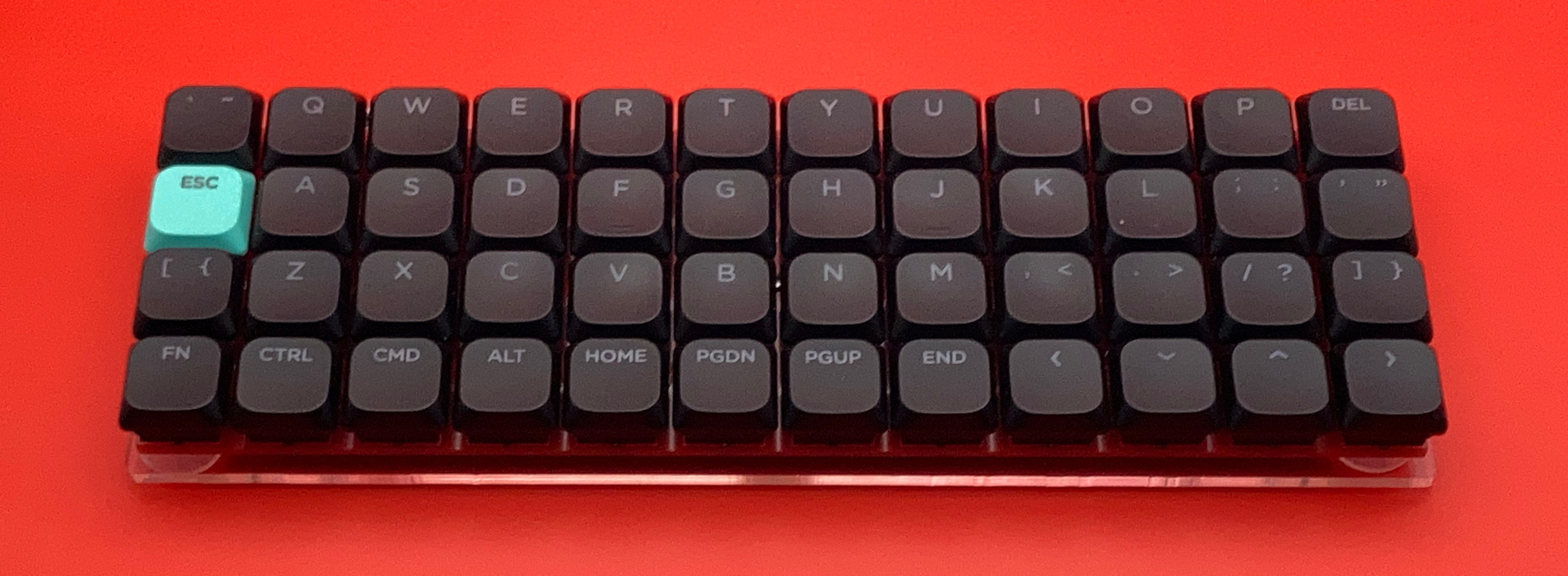 |
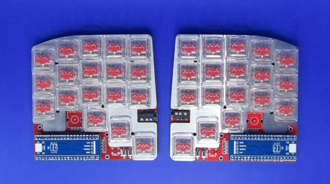
| CH552-36 | 36 key (2x3x5+3), split, column-staggered, MX, sub-100x100, no frills | 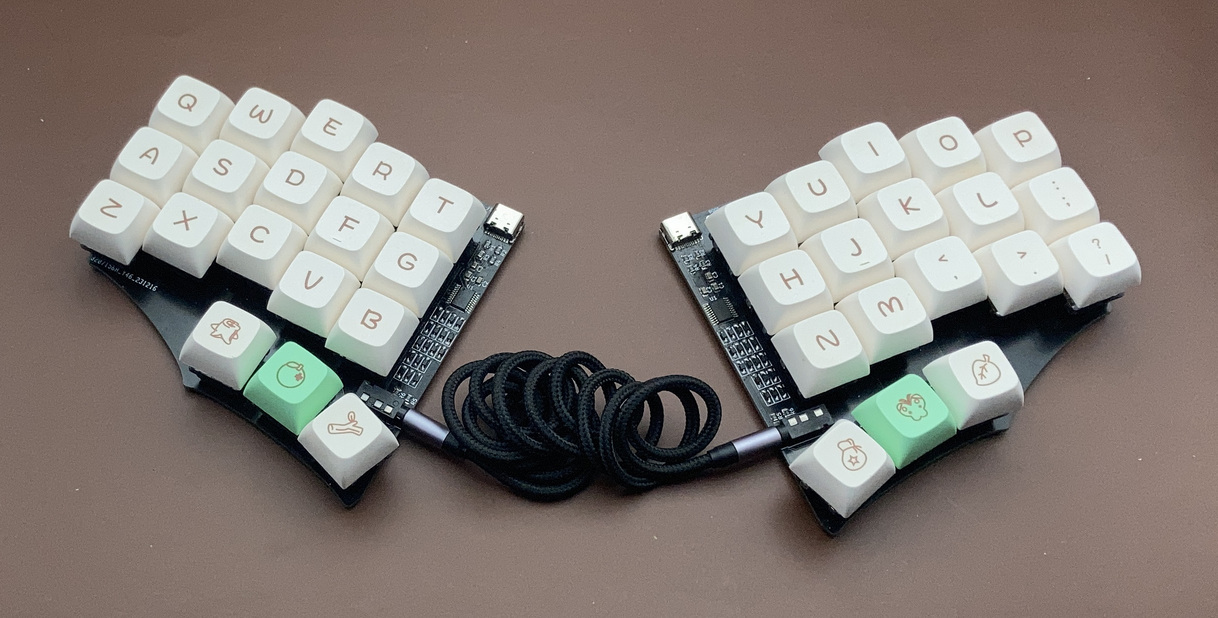 |
Design goals:
- PCB smaller than 100x100 mm2, so that it's cheaper to fabricate at various PCB fabricators.
- Reversible PCB (use the same PCB for left/right halves).
- Using the WeAct Studio MiniF4 "black pill" dev board, a cheap STM32F4 dev board that runs ARM.
- Low profile (PCB + choc switches + bumpons).
- Column-staggered arrangement of key switches.
- Fancy features: e.g. per-key RGB LEDs, rotary encoders, OLED screen, DC vibration motors.
Pictures:
X-1, rev2021.5, MX variation (with rotary encoder, OLED, etc.).
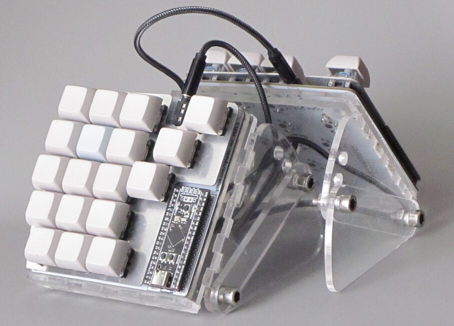
X-1, rev2021.5, Choc variation, low-profile (with flipped GD-32 Bluepill devboards).
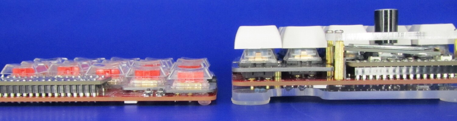
Height comparison between low-profile build (with Choc switches) and with sandwich-case.
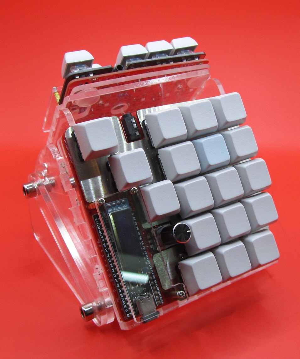
Tented.
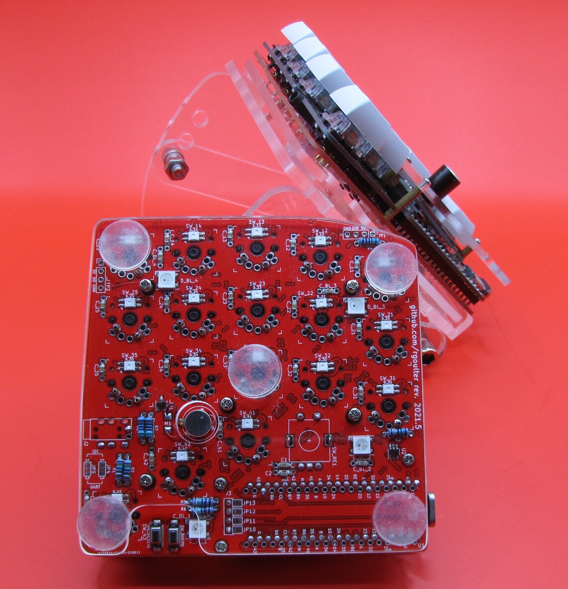
Showing the underside of the PCB through the acrylic bottom layer.


2D Renders of the PCB, revision rev2021.5
-
Blank Layout at keyboard-layout-editor.com.
-
rgoulter's Layout at keyboard-layout-editor.com.
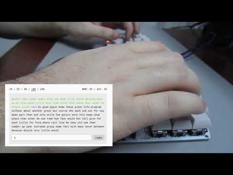
typings.gg:
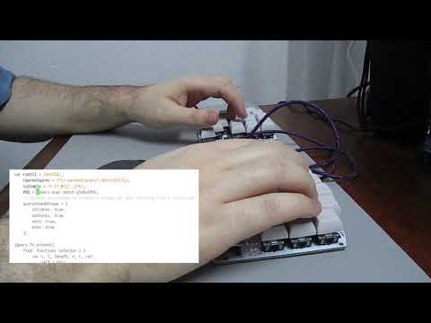
typing.io:
peej's lumberjack-keyboard is a cool and creative design, which continues the style of "show the components" used by keyboards like the plaid.
One downside to it is that DIP microcontrollers are relatively weak. Development boards are a spiritual-successor to DIP microcontrollers, so I wanted to adapt the striking Lumberjack design to a more powerful development board.
Design goals:
- Using STM32 dev board. (ARM-powered!).
- Adapt the Lumberjack design.
- In a "show the components" style.
- Fits in tray-mount GH60 case.
- (Relatively) easy to solder.
Pictures:
X-2 PCB assembled, using a Bluepill devboard, with MX switches, in a cheap GH-60 case.
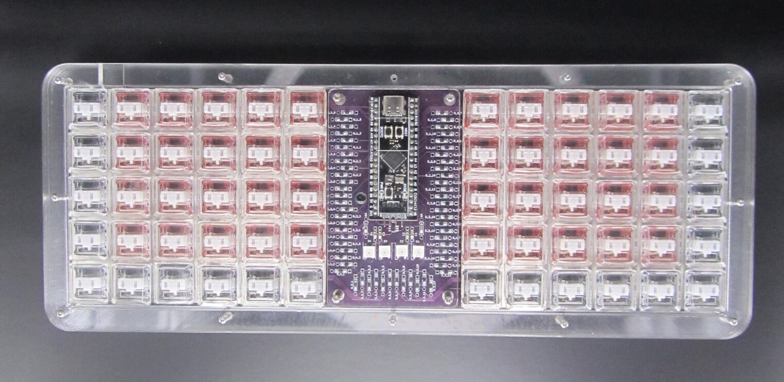
X-2 PCB assembled, using a WeAct Studio MiniF4 "Blackpill" devboard, with Choc switches, in a layered acrylic case.


2D Renders of the PCB, revision rev2021.1
X-2 HSRGB: 5x12 Ortholinear, ARM-powered Adaptation of peej's Lumberjack PCB, with HotSwap and per-key RGB
A fancier version of the X-2 above. With all the benefits of the X-2 (fits in GH-60 case, powerful microcontroller), but with a RGB lighting, which makes the keyboard a bit fancier.
Design goals:
- Same as X-2:
- Using STM32 dev board. (ARM-powered!).
- Adapt the Lumberjack design.
- In a "show the components" style.
- Fits in tray-mount GH60 case.
- (Relatively) easy to solder.
- Additional fancy features:
- HotSwap: the PCB uses Kailh's MX Hotswap sockets. This allows being able to swap out which switches are used by the keyboard, without needing to resolder (or resort to using PCB rivets).
- RGB lighting: the PCB allows for putting RGB lights under each key, as well as RGB underglow.
Pictures:
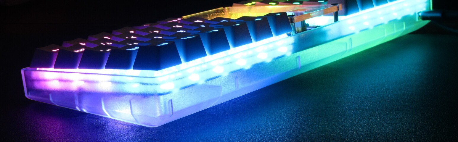
X-2 HSRGB PCB assembled, using a Bluepill devboard, with MX switches, in a cheap GH-60 case. Using MX switches with transparent housing, like Kailh's Jellyfish switches, enhances the RGB lighting.
X-2 HSRGB PCB assembled, view of the back.
My first PCBA design.
Takes jpconstantineau's PyKey60, and arranges a no-frills (no RGB, no hotswap, no speaker) subset of it to be a drop in replacement for the BM40/JJ40 PCB.
Design goals:
- As this is my first PCBA design: a simple design that works.
Pictures:


2D Renders of the PCB, revision rev2023.3
A 4x12 ortholinear with hotswap sockets, and per-key RGB and underglow, using the RP2040 MCU, with mounts compatible with the JJ40/BM40.
Design goals:
-
Fancy features: hotswap sockets, RGB.
-
Same mounting holes as JJ40/BM40/PyKey40.
Pictures:
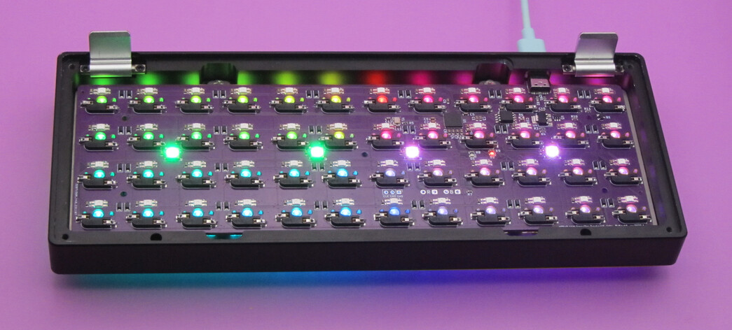
PyKey40 HSRGB PCB assembled in a high-profile aluminium case.


2D Renders of the PCB, revision rev2023.1
A very simple, hand-solderable PCB which uses the Raspberry Pi Pico dev board.
I made this design because in my first attempt at designing a CNC case for the PyKey40, I put the cutout for the USB connector in the wrong place. Having a design which doesn't use a USB connector underneath the PCB works around this.
The form factor encourages the thumbs to use 2-3 keys each (and rely on the pinky fingers less).
Design goals:
-
Simple, hand-solderable PCB.
-
Uses Raspberry Pi Pico devboard. / Doesn't use USB connector underneath PCB.
-
Same mounting holes as JJ40/BM40/PyKey40.
-
Same pinout as PyKey40 (PyKey60).
Pictures:
Pico42 PCB assembled with MX switches, in a low profile aluminium case.
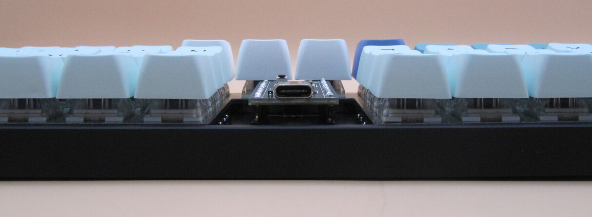
Height of the Pico mounted on round-pin male headers in female headers.
Pico42 PCB assembled with Kailh Choc switches, in a sandwich case.
Underside of the Pico42 in a sandwich style case.


2D Renders of the PCB, revision rev2023.2
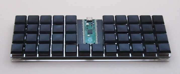
A very simple, hand-solderable 44-key PCB which uses the WeAct Studio's CH552 devboard.
The form factor encourages the thumbs to use 2-3 keys each (and rely on the pinky fingers less).
The keyboard uses semickolon's fak firmware, which uses the sophisticated and modern Nickel configuration language to declare keyboard and keymap definitions.
The CH552 is cheaper than the RP2040, although is much less powerful. e.g. you're probably not going to get Vial on a CH552 keyboard. In practice, fak seems well suited for small-keyboard enthusiasts.
Since the CH552 has relatively few GPIO pins, the matrix uses 7 rows of 7 columns (= 14 GPIO pins), rather than a more traditional 4 rows of 12 columns (which would use 16 GPIO pins).
Design goals:
-
Low Budget.
-
Simple, hand-solderable PCB.
-
Same mounting holes as JJ40/BM40/PyKey40.
Pictures:
CH552-44 (rev2023.1) in a sandwich style case.
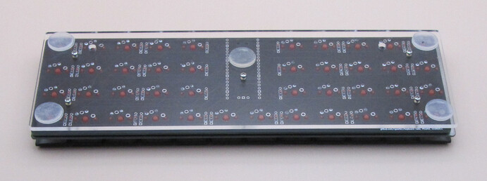
Underside of the CH552-44 (rev2023.1) in a sandwich style case.


2D Renders of the PCB, revision rev2023.2
- Firmware: NCL files provided under
ncl/at https://github.com/rgoulter/fak
(NOTE: for flashing new firmware, on Windows, I recommend the official WCHISPTool. For flashing using open-source software, it's much easier to flash firmware onto the CH552 from Linux, e.g. docs/guide-liveiso-flashing-fak.md).
A bottom plate can be used to protect the components underneath the PCB.
Source files for plates to cut (or cases to 3D print) can be found under cad/ in this repository.
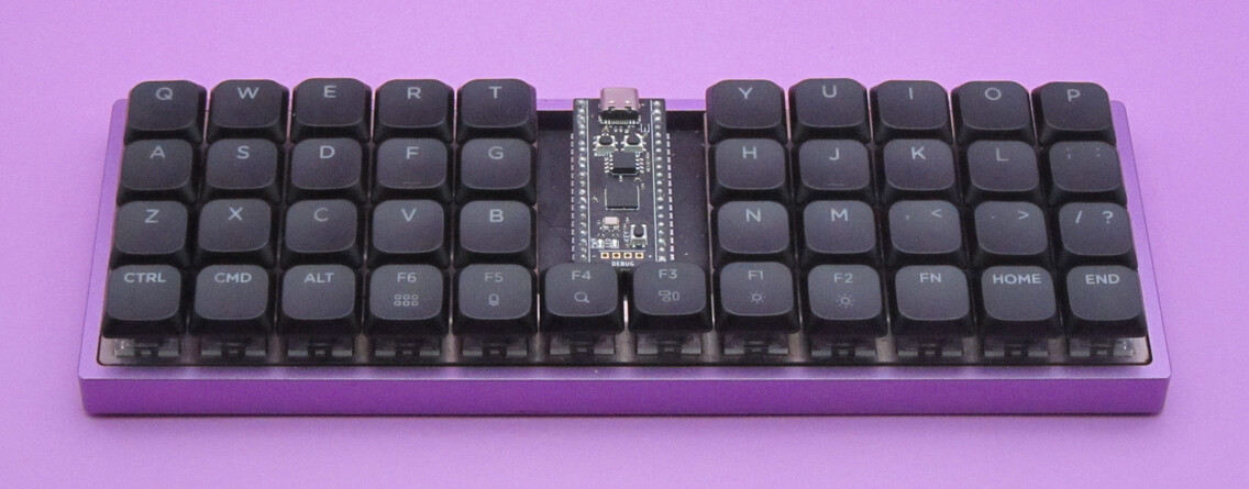
A very simple 48-key PCBA which uses the CH552 MCU.
The keyboard uses semickolon's fak firmware, which uses the sophisticated and modern Nickel configuration language to declare keyboard and keymap definitions.
The CH552 is cheaper than the RP2040, although is much less powerful. e.g. you're probably not going to get Vial on a CH552 keyboard. In practice, fak seems well suited for small-keyboard enthusiasts.
Since the CH552 has relatively few GPIO pins, the matrix uses 7 rows of 7 columns (= 14 GPIO pins), rather than a more traditional 4 rows of 12 columns (which would use 16 GPIO pins).
Design goals:
-
PCBA and Ortho 4x12 improvement upon the CH552-44.
-
Low Budget.
-
Use CH552 for the fak firmware.
-
Same mounting holes as JJ40/BM40/PyKey40.
Pictures:
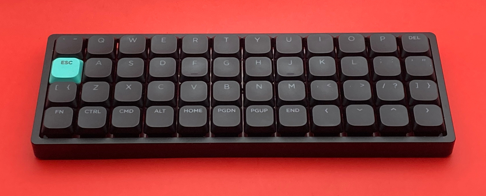
CH552-48 in a sandwich style case.
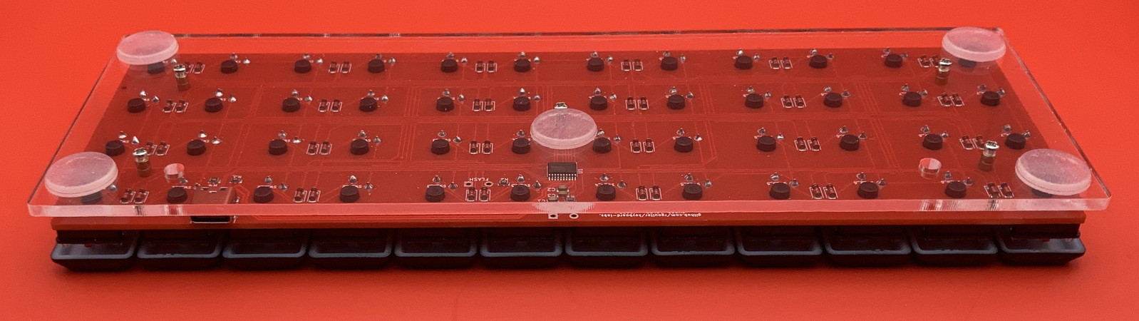
Underside of the CH552-48 in a sandwich style case.
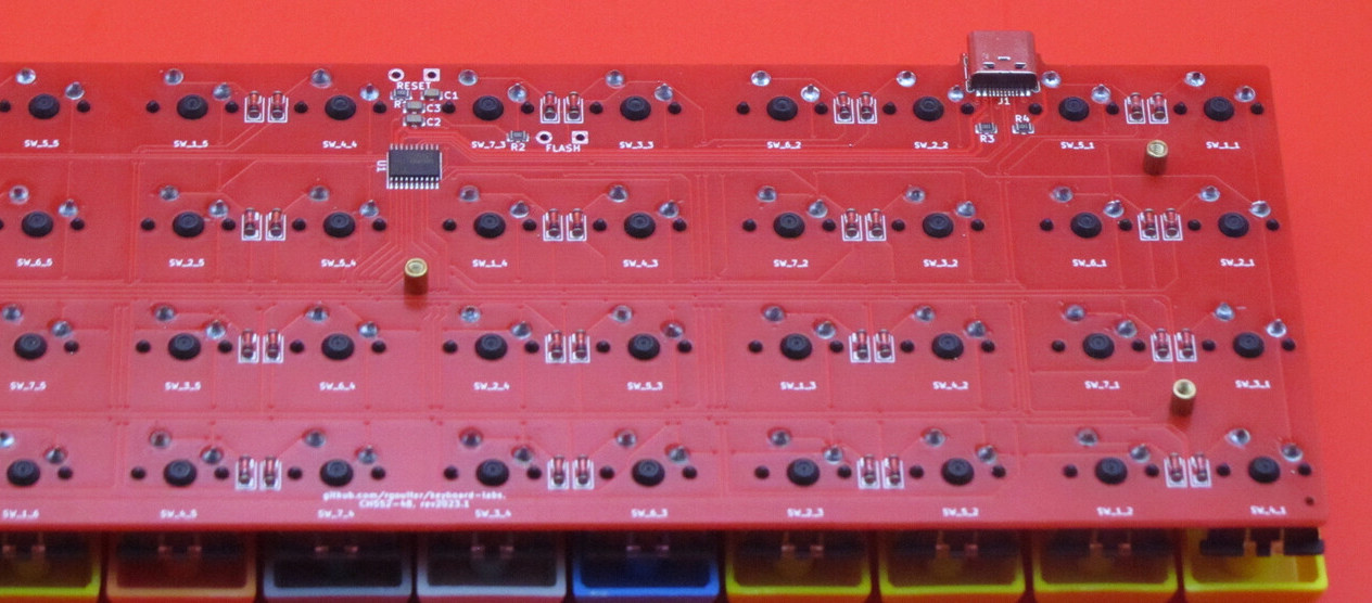
Underside of the CH552-48, showing the PCBA components..


2D Renders of the PCB, revision rev2023.1
- Firmware: NCL files provided under
ncl/at https://github.com/rgoulter/fak
(NOTE: for flashing new firmware, on Windows, I recommend the official WCHISPTool. For flashing using open-source software, it's much easier to flash firmware onto the CH552 from Linux, e.g. docs/guide-liveiso-flashing-fak.md).
A bottom plate can be used to protect the components underneath the PCB.
Source files for plates to cut (or cases to 3D print) can be found under cad/ in this repository.
Variation of the CH552-48 which uses Redragon low profile switches.
Redragon low profile switches are significantly cheaper than other low profile switches, especially the popular Kailh Choc v1 switches.
Height varies depending on keycap profile. The distance between the top of the PCB and the top of the keycap is around 11mm for Redragon low profile switches with low profile keycaps. (In comparison, the same measurement is 10-11mm for Kailh Choc v1, and about 20mm for MX).
Unlike MX switches (where switches from different manufacturers will have compatible pin positions), different "low profile" switches have different pin positions from each other. So, to use Redragon "low profile" switches, you need a PCB designed for Redragon low profile switches.
The KiCad footprint I used for this design can be found under pcb/ in this repository.
Redragon switches support keycaps with MX stems, unlike Kailh Choc v1. Albeit, general MX keycap profiles (e.g. XDA) are NOT fully compatible with "low profile" switches, since the bottom of the keycap bottoms-out below where a switch plate sits. Instead, "low profile" switches with MX stems need 'slim' keycaps, such as NuPhy's or womier's, etc.
Since the Redragon low profile switches have 3-pins, it's best to assemble the keyboard using a switch plate (e.g. a lasercut 1.0mm metal plate). Pictures below show what a build without a plate looks like.
Design goals:
- A keyboard that uses Redragon low profile switches.
Pictures:
CH552-48-LPR in a JJ40 low profile aluminium case.
CH552-48-LPR in a sandwich style case.
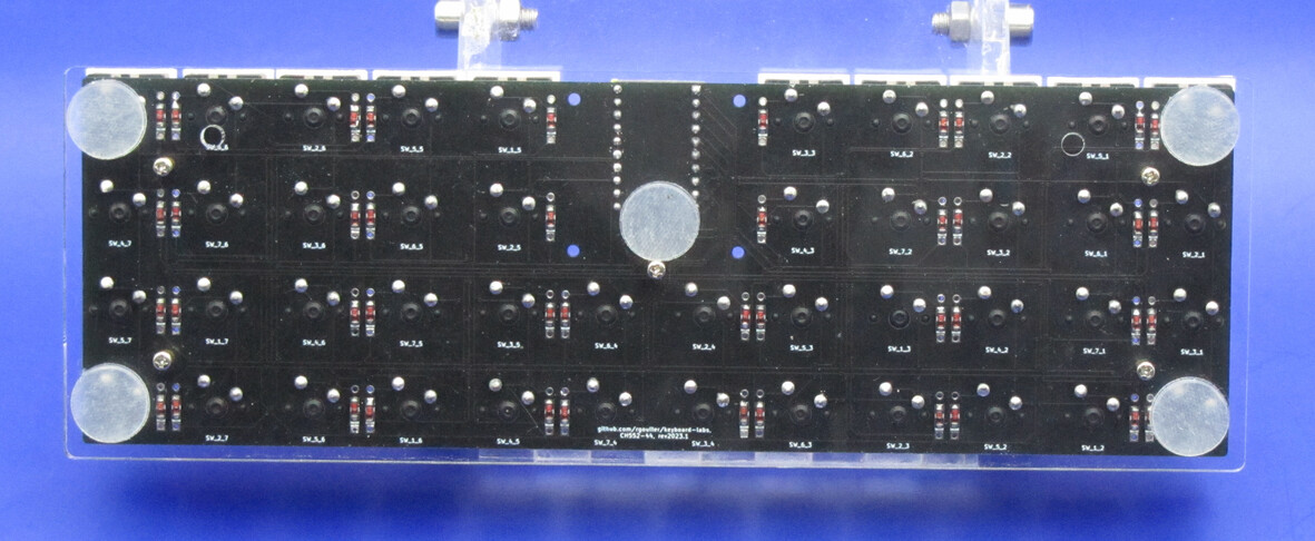
Underside of the CH552-48-LPR in a sandwich style case.
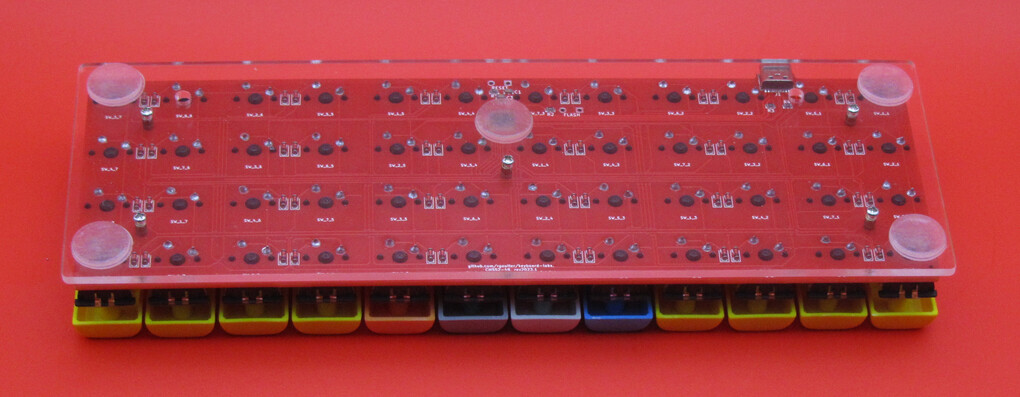
Switches mounted to the PCB without a plate.
Unsoldered underside of the PCB, with switches mounted in a plate.


2D Renders of the PCB, revision rev2023.1
Same as for the CH552-48.
Firmware: NCL files provided under ncl/ at https://github.com/rgoulter/fak
(NOTE: for flashing new firmware, on Windows, I recommend the official WCHISPTool. For flashing using open-source software, it's much easier to flash firmware onto the CH552 from Linux, e.g. docs/guide-liveiso-flashing-fak.md).
A bottom plate can be used to protect the components underneath the PCB.
Source files for plates to cut can be found under cad/ in this repository.
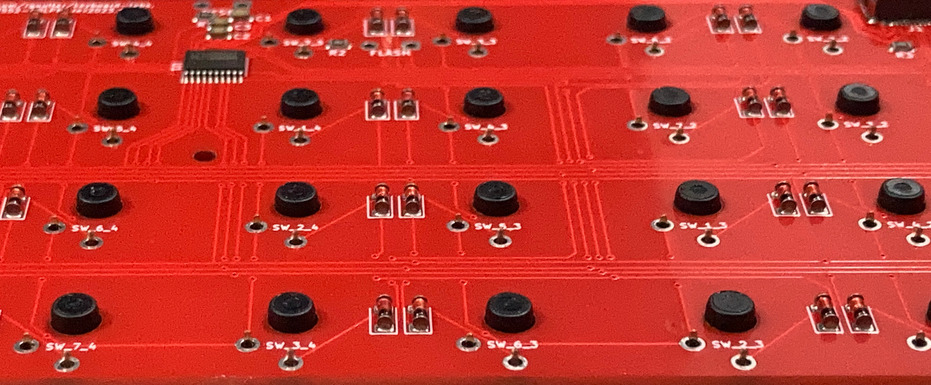
A very simple, 36-key PCB which uses the CH552 MCU.
The design takes inspiration from TeXitoi's keyseebee.
The PCB is smaller than 100x100 mm2, so that it's cheaper to fabricate at various PCB fabricators.
The keyboard uses semickolon's fak firmware, which uses the sophisticated and modern Nickel configuration language to declare keyboard and keymap definitions.
Design goals:
-
Low Budget.
-
Use CH552 for the fak firmware.
-
"Show the components", "just a keyboard" and "only a PCB with SMD components" from the KeySeeBee.
Pictures:
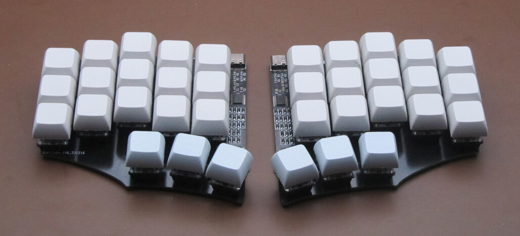
CH552-36.
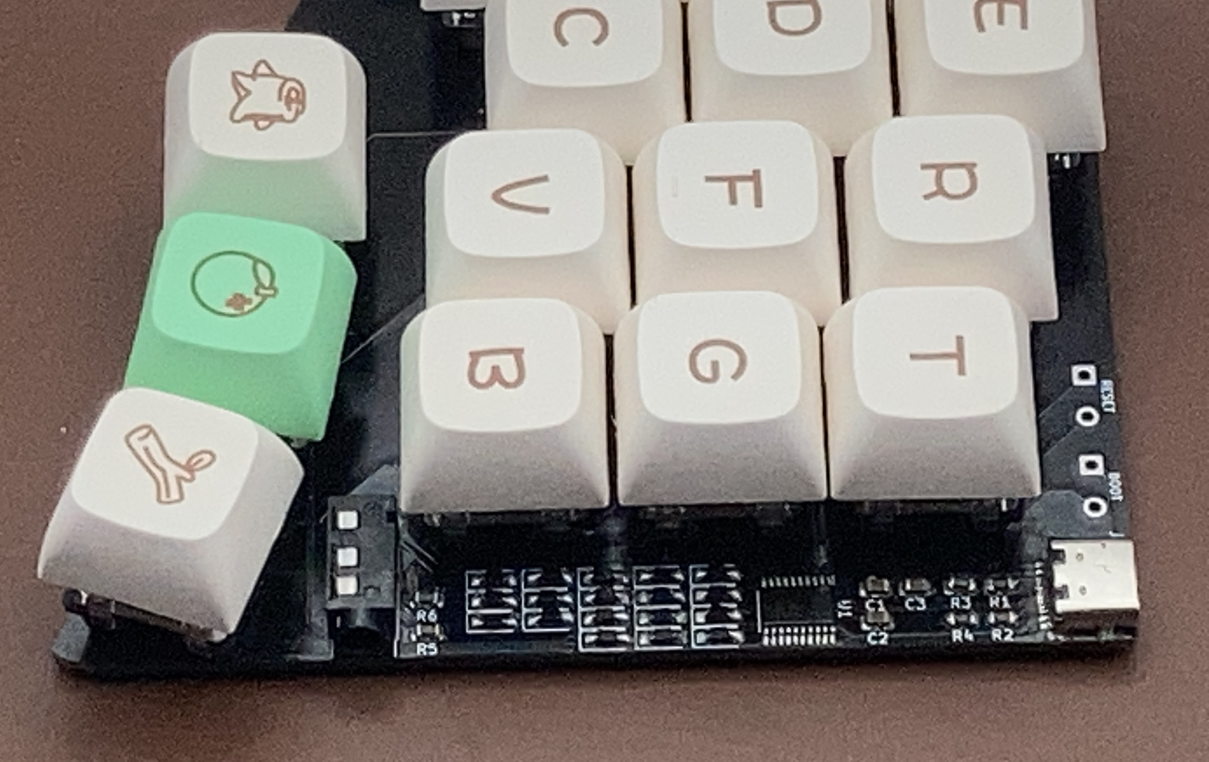
CH552-36, close up of the MCU area.
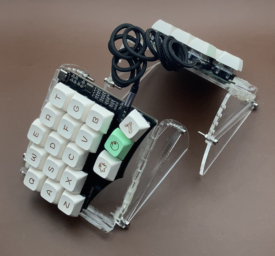
CH552-36, tented, with a coiled TRRS cable.
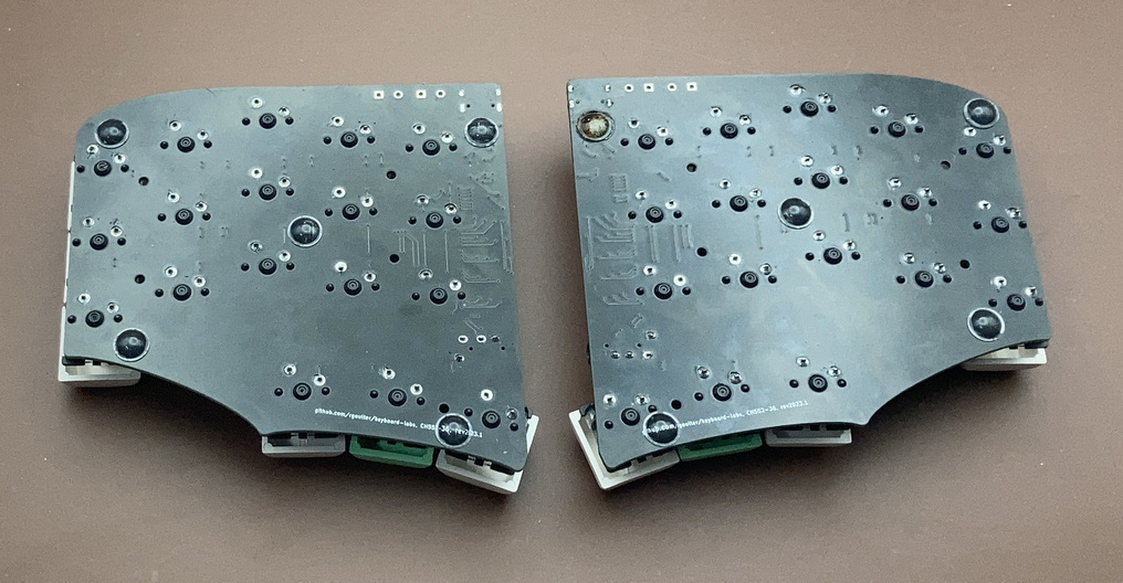
Bottom of CH552-36.


2D Renders of the PCB, revision rev2023.1
- Firmware: NCL files provided under
ncl/at https://github.com/rgoulter/fak
(NOTE: for flashing new firmware, on Windows, I recommend the official WCHISPTool. For flashing using open-source software, it's much easier to flash firmware onto the CH552 from Linux, e.g. docs/guide-liveiso-flashing-fak.md).
CAD design files found under cad/:
keyboard_tenting_stand.scad describes a design which can be laser cut
and assembled to form a adjustable tenting stand. The stand can be adjusted
using an extra wedge piece.
The design accepts various parameters (e.g. width, height, angle, screw diameter).
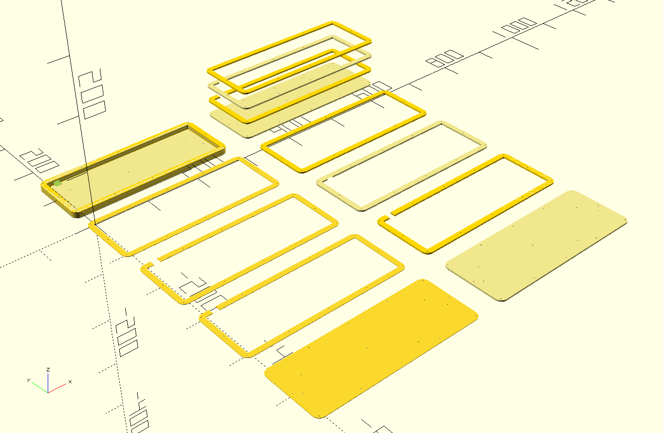
An OpenSCAD module which helps for modelling the layers for a layered acrylic case.
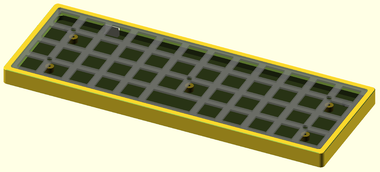
A set of OpenScad files for a parameterised simple keyboard case design.
I've used outputs from these for CNC milling, as well as for 3D printing.
The case has several parameters, so it should be suitable for a variety of rectangular-shaped PCB keyboards.
The CNC case, mounting a Pico42.
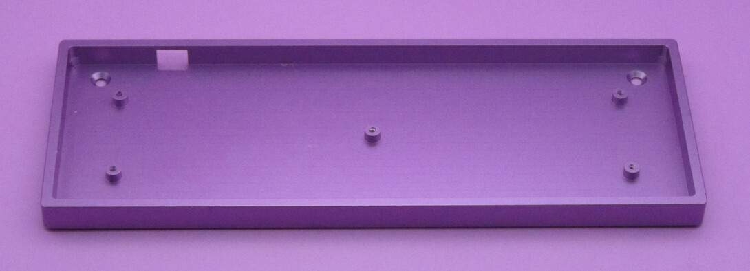
The CNC case, top.
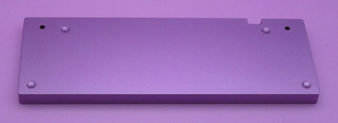
The CNC case, bottom.
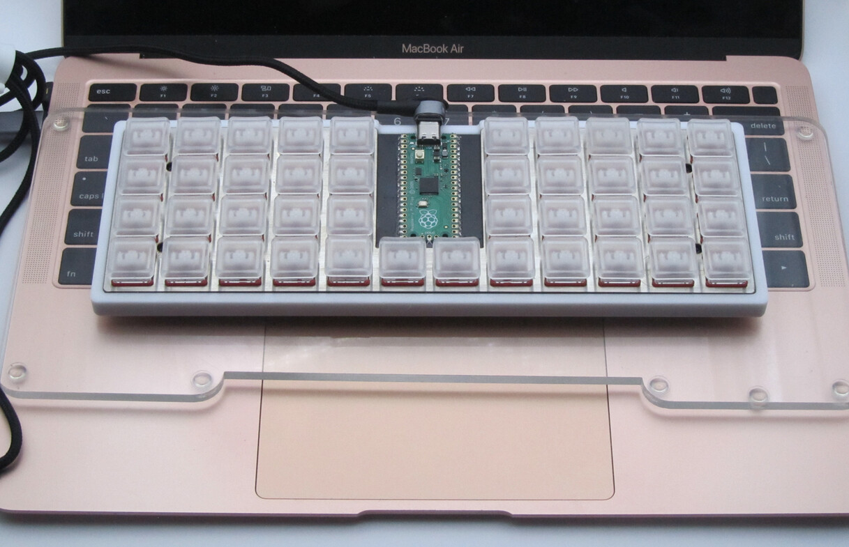
The 3D Printed Pico42 case, mounting a Pico42 with Choc switches, sitting on a laptop's keyboard.
![]()
The 3D Printed Pico42 case, top.
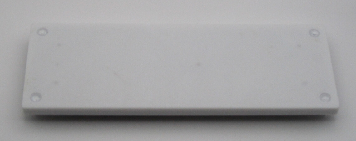
The 3D Printed Pico42 case, bottom.
Preview of the case in OpenScad.
Source files under firmware.
QMK is the most practical firmware I've used for small
keyboards. I maintain firmware for my keyboards and my layouts in a downstream
GitHub
repository
on the branch rgoulter-keyboards-and-layouts. (This branch will get rebased
onto qmk's develop branch from time to time). My code will get synced into the firmware/qmk directories.
There is some code for the CircuitPy keyboard firmware KMK. (Although, at the time of writing, KMK doesn't handle home row modifiers well, so IMO it's less suitable for small keyboards as-is).
There is also keyboard firmware written in Rust using the keyberon
firmware under firmware/keyberon.
My attempt at generating top/bottom plate CAD files as code.
The script generates an OpenSCAD file with the .kicad_pcb data
(Kicad module positions, board outline as an OpenSCAD module, etc.), which can be used by other OpenSCAD
code.
See: scripts/README.MD
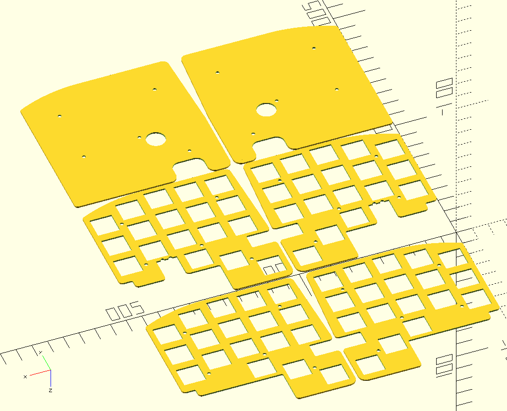
Example output of OpenSCAD code, which makes use of the Kicad PCB data to construct a variety of keyboard plates.
-
docs/guide-liveiso-flashing-fak.md: guide for using the Live ISO on a bootable USB to flash Fak firmware.
-
docs/pcb-rivets.md: notes on usage of PCB rivets for allowing hot-swapping switches on PCBs with regular footprints.
-
docs/socketing-devboards.md: some comparison photos of some different ways of socketing devboards.
-
docs/rgb-leds-logic-level-shifting.md: some notes on logic level shifting.
-
docs/stm32-flashing-and-bootloaders.md: some notes on bootloaders for STM32.
-
cad/docs/freecad-techdraw-threads.md: notes on how to use FreeCad to create a technical drawing to indicate location of threads to be tapped, or where inserts are to be placed.