Authors: Peiyu Liao, Stephanie Wang

We've connected an ESP8266 WiFi module to our pi, which can be used to talk to servers via WiFi and send over data that has been gathered by sensors, or talk with another ESP8266 module.
The firmware running on the ESP is NodeMCU, and includes a Lua interpreter. We send Lua programs to run on the module via the ESP's UART.
Because our pi has only one hardware UART (one set of TX, RX pins), we implemented a software UART choosing two arbitrary GPIO pins as the TX, RX pins. Thus our pi communicates with unix via the software UART, and also communicates with the ESP module via the native UART.
As a project to demonstrate the ability to communicate between the Pi and the ESP, we extended the lab10-shell to launch a shell that sends Lua commands to the ESP. Other applications can take reference from the pi-side shell code to communicate with the ESP.
Our final demonstration shows that we can use our ESP as a client to communicate with a server, which is useful for projects that require networking.
- Hardware
- Prepare an ESP8266 module with NodeMCU firmware. Here we use the Adafruit HUZZAH ESP8266 breakout.
- Connect your USB-TTL adapter from your laptop to the software UART GPIO pins. In our implementation, GPIO 5 is assigned as TX, and GPIO 6 is assigned as RX. You can change the pin assignments in sw-uart-libpi/sw-uart.h.
- Connect the ESP's dedicated UART pins to the native UART pins on your pi. Connect the power line to either 5V or 3.3V.
- Software UART Bootloader
- Copy bootloader/pi-side/kernel.img to your SD card as
kernel.img, as our bootloader is now modified to use the software UART.
- Copy bootloader/pi-side/kernel.img to your SD card as
- Run the Pi shell
- Plug in your Pi.
- Set
LIBPI_PATHto the sw-uart-libpi directory.- Open
~/.bashrcand writeexport LIBPI_PATH="/path/to/sw-uart-libpi". - Run
source ~/.bashrc.
- Open
- Change directory to project and run
makein the project folder. - Change directory to project/shell-unix-side and run
make run, which will use the software UART tomy-installthe pi-shell program. Now you should see a the pi-shell prompt.
- Run the ESP shell
- Enter
espto open the ESP shell, which tells the Pi to communicate with the ESP. - You will be asked to reset the ESP which is necessary to launch the Lua interpreter. Long press on the reset button on the ESP and release. You will see a "Welcome!" message.
- Enter some Lua commands that will be sent over to the Pi to control the ESP.
- Try the following commands to turn on the LED light:
gpio.mode(3, gpio.OUTPUT)gpio.write(3, gpio.LOW)
- The commands will be echoed back to you from the Pi. These do not come from the ESP.
- Try the following commands to turn on the LED light:
- Exit the ESP shell by entering
exit. This takes the unix shell back to the original Pi shell state.
- Enter
Your terminal should look similar to this:
$ make run
../bootloader/unix-side/my-install -exec ./pi-shell ../shell-pi-side/pi-shell.bin
my-install: going to clean up UART
my-install: about to boot
Sending program binary......................................Done.
PIX:> esp
PIX:buildin cmd
PIX:esp cmd
ESP:Please reset your ESP8266...
ESP:Welcome!
ESP:> gpio.mode(3, gpio.OUTPUT)
ESP:pi echoed: <gpio.mode(3, gpio.OUTPUT)>
ESP:> gpio.write(3, gpio.LOW)
ESP:pi echoed: <gpio.write(3, gpio.LOW)>
ESP:> exit
ESP:ESP shell exited
PIX:> ^CPIX:
got control-c: going to shutdown pi.
PIX:builtin cmd: reboot
make: *** [run] Interrupt: 2

PIX:PI REBOOT!!!
PIX:pi rebooted. shell done.Software UART is a bit banging technique that performs serial communication over two GPIO pins in a low-level way. To free up the native UART port for the ESP, we implemented a software UART and adapt our bootloader and my-install programs to use it. sw-uart-libpi/sw-uart contains the implementation of the software UART.
You will see
gpio-intandtimer-intin the package, which is the original RX implementation that detects the start signal using GPIO interrupts. We have get rid of the interrupt implementation and used a busy-waiting loop instead. You can ignore these two folders and theint_handler()function insw-uart.c. We left it there since it works if you uncomment line 119 insw-uart.cin thesw_uart_init_rx()function that enables the interrupts.
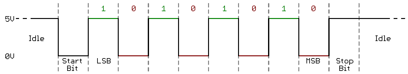
In the UART protocol, a byte transmitted is preceded with a start bit (low signal) and ends with a stop bit (high signal), hence a total of 10 bits. The line is held high when idle. The time delay between two bits is 1 / baudrate, e.g. it is 104 μs for a baudrate of 9600.
The steps for implementing the software TX / RX pins are thus:
- TX pin
- Sends a low signal (start bit). Delay for 104 μs.
- Sends the 8 bits of the data byte. Delay each for 104 μs.
- Sends a high signal (stop bit). Delay for 104 μs.
- RX pin
- Waits for a low signal (start bit). Delay for 104 μs.
- Reads 8 bits of data. Delay each for 104 μs.
- Reads a high signal (stop bit).
Software UART is less reliable than a native UART port. If we are using it to transmit a lot of data, it is better to do some hacks to ensure a zero data corruption rate.
The method we use is to transmit a byte redundantly and let the receiving side vote for the correct byte. We refer to this method as the robust method. There can be other hacks such as increasing the bit sampling rate, which is more ideal since we don't need to change the code at the transmission side and also should be more efficient.
Originally the bootloader talks over the native UART port with a 115200 baudrate. We will lower this value to 9600 so as not to raise the data corruption risk of software UART. In addition, we also set the baudrate of the native UART that talks to the ESP to 9600.
Here are the values to be updated:
- Software UART baudrate (pi-side): set
DELAYin sw-uart-libpi/sw-uart.h - Hardware UART baudrate (unix-side): pass the correct argument to
set_tty_to_8n1in project/bootloader/unix-side/my-install.c - Hardware UART baudrate (pi-side): set
AUX_MU_BAUD_REGinuart_init()to the correct value in sw-uart-libpi/my-uart.c
After the putc and getc methods are implemented for the software UART, we can easily switch between the methods of native uart and software uart by e.g. defining a macro in bootloader/shared-code/simple-boot.h. Now the bootloader and my-install knows they should use the robust method for communication.
Another thing to note is the timout issue of the file descriptor. In our bootloader protocol, my-install waits for the ACK signal after sending the binary data and the EOT signal. If we implement the robust method, the data transmission may take too long, and my-install may timeout on waiting for ACK.
One solution is to increase the timeout time of the file descriptor in bootloader/unix-side/my-install.c. A possibly better solution, which is implemented, is to let the bootloader send back an ACK every several bytes of data received. See get_binary() function in bootloader.c and send_binary() function in simple-boot.c.
We create an interface connected to the Lua interface of the ESP through the Pi. This way we can send Lua commands to the ESP as if the ESP is directly connected to the unix side. This may not seem useful as a practical application, but it demonstrates that the Pi can talk to and control the ESP through the native UART port, and hence we can say that the Pi is equipped with a network function.
The ESP shell is integrated with the Pi shell from lab10. It can be opened by sending an esp command to the Pi shell and exited by sending an exit command.
The esp() function in project/shell-unix-side/pi-shell.c handles the ESP shell interface. It is straightforward, just reading the commands from user and send it to Pi, and read the response from the Pi.
Note that the ESP takes commands that end with \r\n, i.e. CRLF line endings, hence we need to wrap the commands a bit before passing to Pi.
The strncmp(buf, "esp", 3) == 0 branch section in notmain() of project/shell-pi-side/pi-shell.c opens the communication channel with ESP. It reads the commands from the unix side, sends it to ESP, reads the response from ESP, and sends it back to the unix side.
In order to read the response correctly, it is critical to understand how the Lua interface of the ESP works. We experimented with the ESP directly via CoolTerm, and found out that every character sent to the ESP will be echoed back. Thus in the function that writes data, make sure every echoed byte is consumed, or else the response parsed will not be as expected. In addition to the echoed bytes, there are some garbage bytes sent from the ESP after reset. Make sure to read them away.
To read the actual response from the ESP after it executes the command, we simply read bytes until the prompt ">" appears.
We'll send a simple "hello world" from client (our ESP connected to Pi) to a server ESP (setup using CoolTerm). The following scripts are taken from this tutorial on making two ESP8266 talk.
First load the server script below to the server ESP, which creates an access point with the specified ssid and password, and listens for incoming data:
print("ESP8266 Server")
wifi.setmode(wifi.STATIONAP);
wifi.ap.config({ssid="test",pwd="12345678"});
print("Server IP Address:",wifi.ap.getip())

sv = net.createServer(net.TCP)
sv:listen(80, function(conn)
    conn:on("receive", function(conn, receivedData)
        print("Received Data: " .. receivedData)
    end)
    conn:on("sent", function(conn)
      collectgarbage()
    end)
end)
Then send the following commands to the client ESP through the ESP shell, which lets the client connect with the server, and send a "hello world" message to the server:
print("ESP8266 Client")
wifi.sta.disconnect()
wifi.setmode(wifi.STATION)
wifi.sta.config("test","12345678") -- connecting to server
wifi.sta.connect()

print(wifi.sta.getip()) -- make sure you see the ip address

cl=net.createConnection(net.TCP, 0)
cl:connect(80,"192.168.4.1")
cl:send("Hello World!")
You should see "Received Data: Hello World!" appearing on your server side.
- Wrap the communication with ESP into a package and export its interface, instead of scattering the communication details in the pi-shell.
- Implement a tool that loads a lua script file and sends it to ESP.
- Implement a more practical application that sends data to the cloud through the ESP.