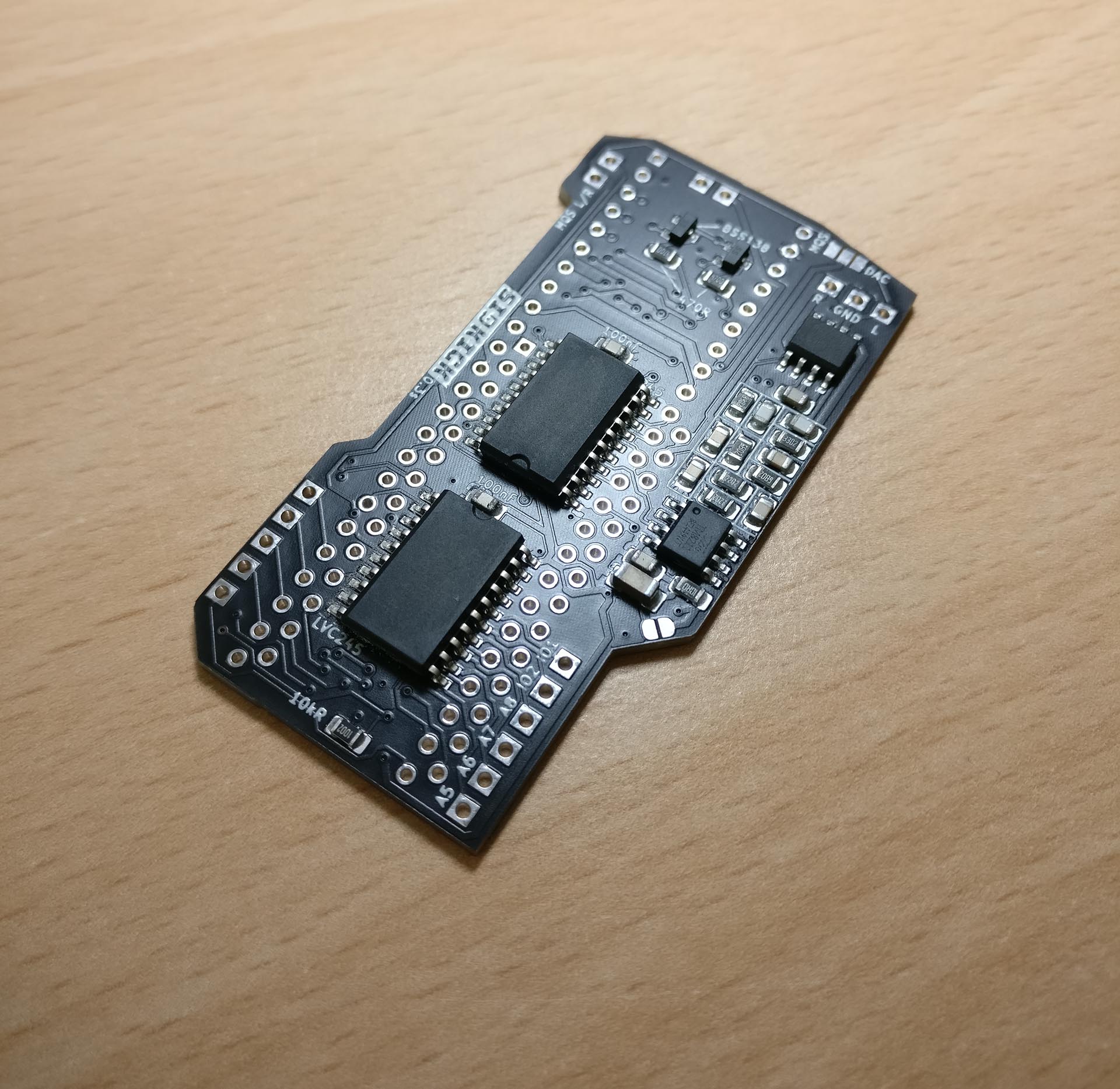
.- the first complete SID replacement that you can build yourself -.
SIDKick is a drop-in replacement for the SID sound chips used in C64s and C128s based on a Teensy 4.1. It is able to emulate two SIDs (6581 and/or 8580), a Sound Expander (offering Yamaha OPL-based FM sound), and a MIDI interface at the same time. It makes no compromises with regard to quality: the emulation is based on reSID and fmOPL. It also comes with a few extras.
Currently its features include:
- dual 6581 and/or 8580 emulation based on reSID 0.16 or reSID 1.0 (configurable)
- 2nd-SID address at $d400, $d420, $d500, $d420 + $d500 simultaneously, $de00, $df00
- Sound Expander/FM emulation based on fmOPL (at $df00)
- paddle/mouse support
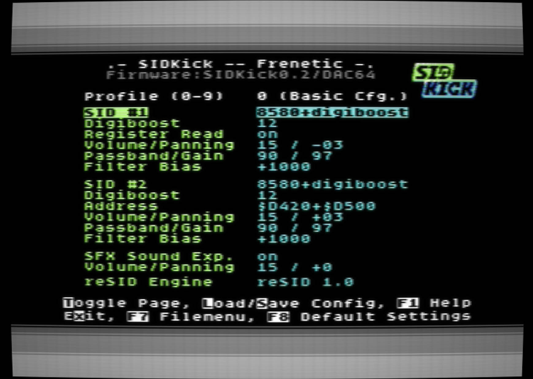
- built-in configuration menu (launch with "SYS 54301" or "SYS 54333", also from C128-mode)
- built-in PRG launcher (via menu)
- 10 different profiles, switchable on-the-fly via an optional button (otherwise via menu), optional "SAM speech synthesis" telling you which one is selected
- MIDI interface emulation and breakout connector (DATEL, Sequential, Namesoft and compatible interfaces based on the MC6850 UART IC, addresses at $de0x) 1
- LED-stripes (WS2812b) support with several display modes (peak meter, color cycling, ...) 1
- sound output via Teensy MQS (PWM) or high-quality using a PT8211/TM8211-DAC, filters, and an operational amplifier
- output available at connectors (stereo) or routed through the mainboard (mono)
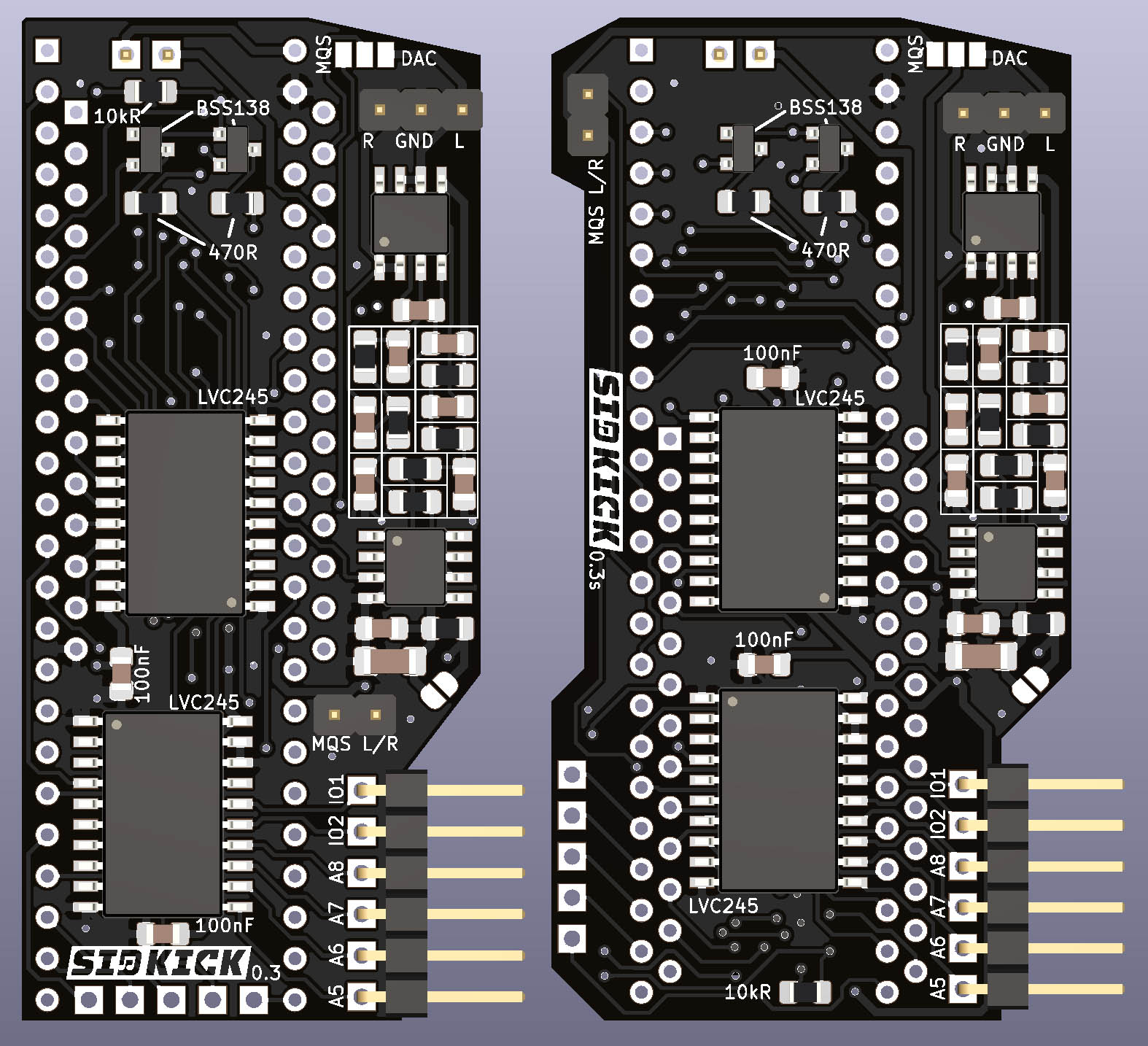
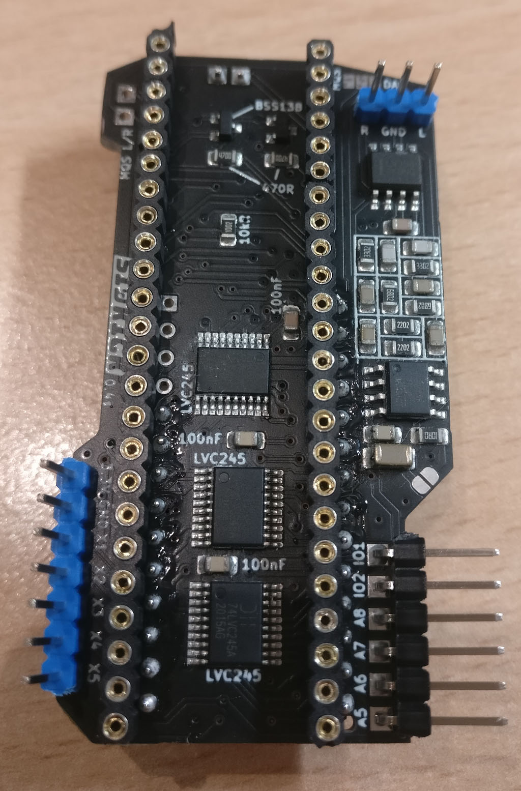
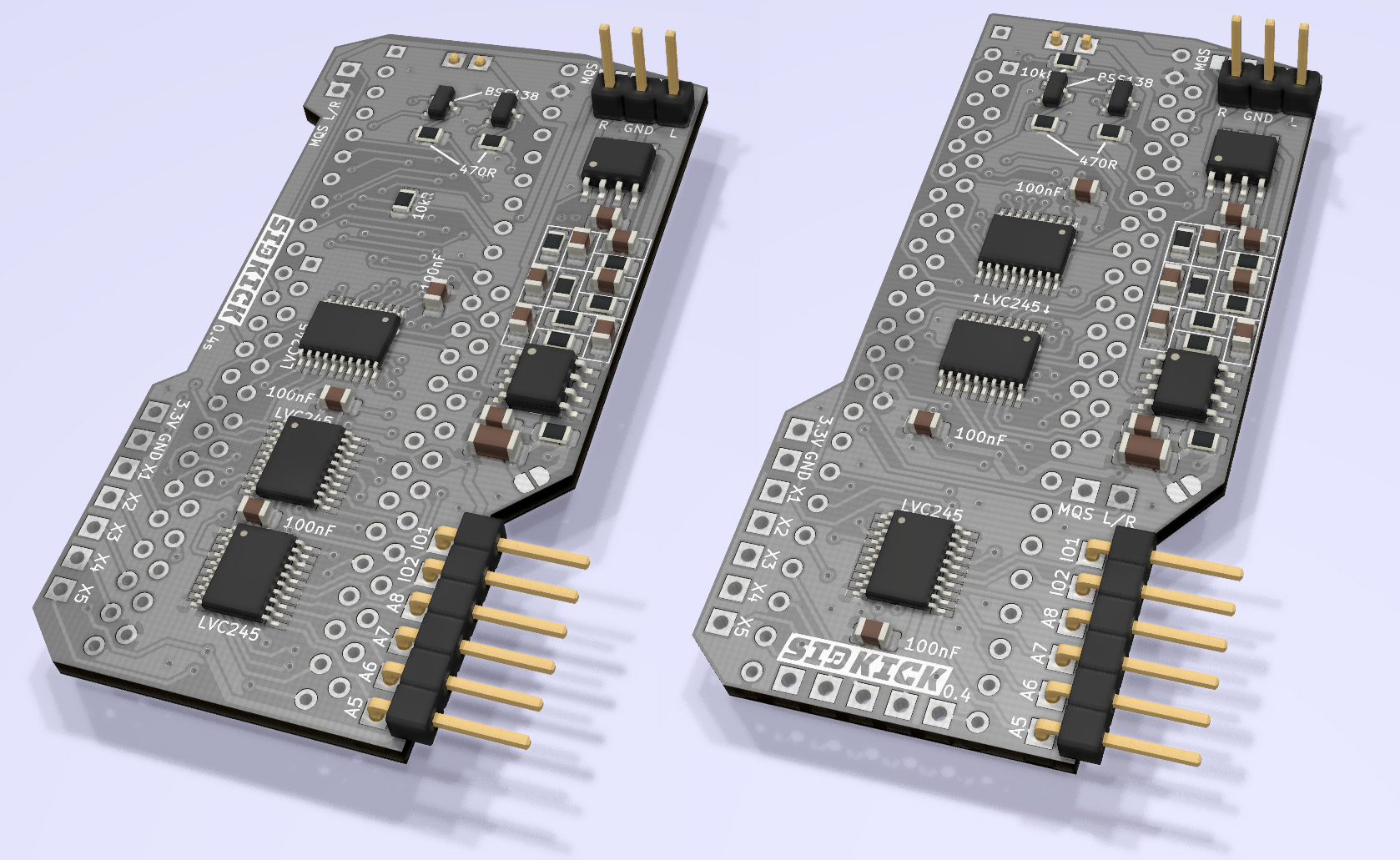
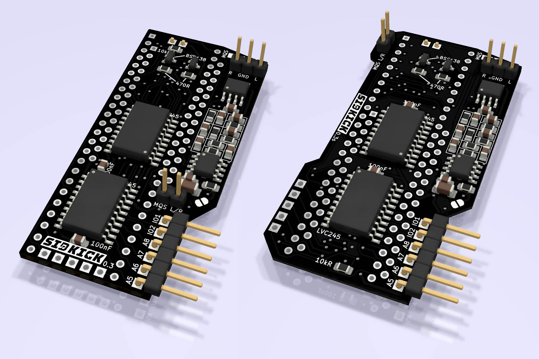
| SIDKick 0.4s | SIDKick PCB 0.4s and 0.4 (rendering) | SIDKick PCB 0.3 and 0.3s (rendering) |
|---|---|---|
 |
 |
 |
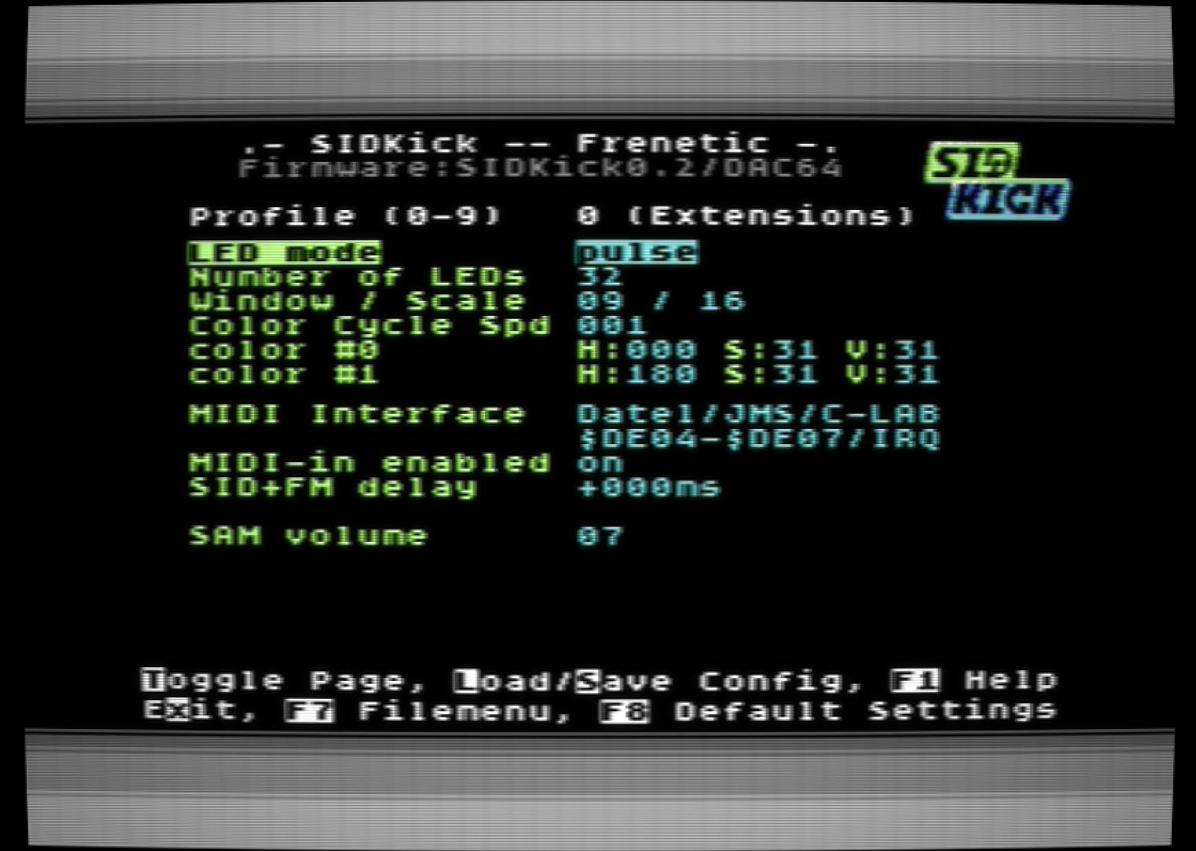
| Built-in configuration tool |
|---|
  |
Videos by emulaThor showcasing the LED-stripe support can be found here.
First of all, there are two variants of the PCB: for C64 longboards (v0.3 and v0.4, left in images above) and for C64 shortboards (v0.3s and v0.4s, right). I prepared the latter as the SIDKick+Teensy combination otherwise barely fits below the keyboard in flat C64c cases unless you use low-profile sockets and pin headers. All 4 PCB-versions fit into a C128; installation in a C128D requires removing a standoff below the power supply and gently lifting it (same as with other dual SID options).
Of both variants there are two revisions: the latest one (v0.4) is a single-sided PCB using smaller IC footprints and provides easy-to-reach 3.3V and GND pins. Both revisions (v0.3 and v0.4) provide extension pins for the SAM button, MIDI, and LED-stripe extensions.
Note, all PCBs provide the same functionality.
Here you can find the BOM and assembly information for SIDKick v0.3, SIDKick v0.3s. SIDKick v0.4, SIDKick v0.4s.
If you plan to use the (lower quality) MQS-output only, you can skip all SMD-parts outside of the SID-/Teensy-sockets (C101-109, R101-107, U2, U6).
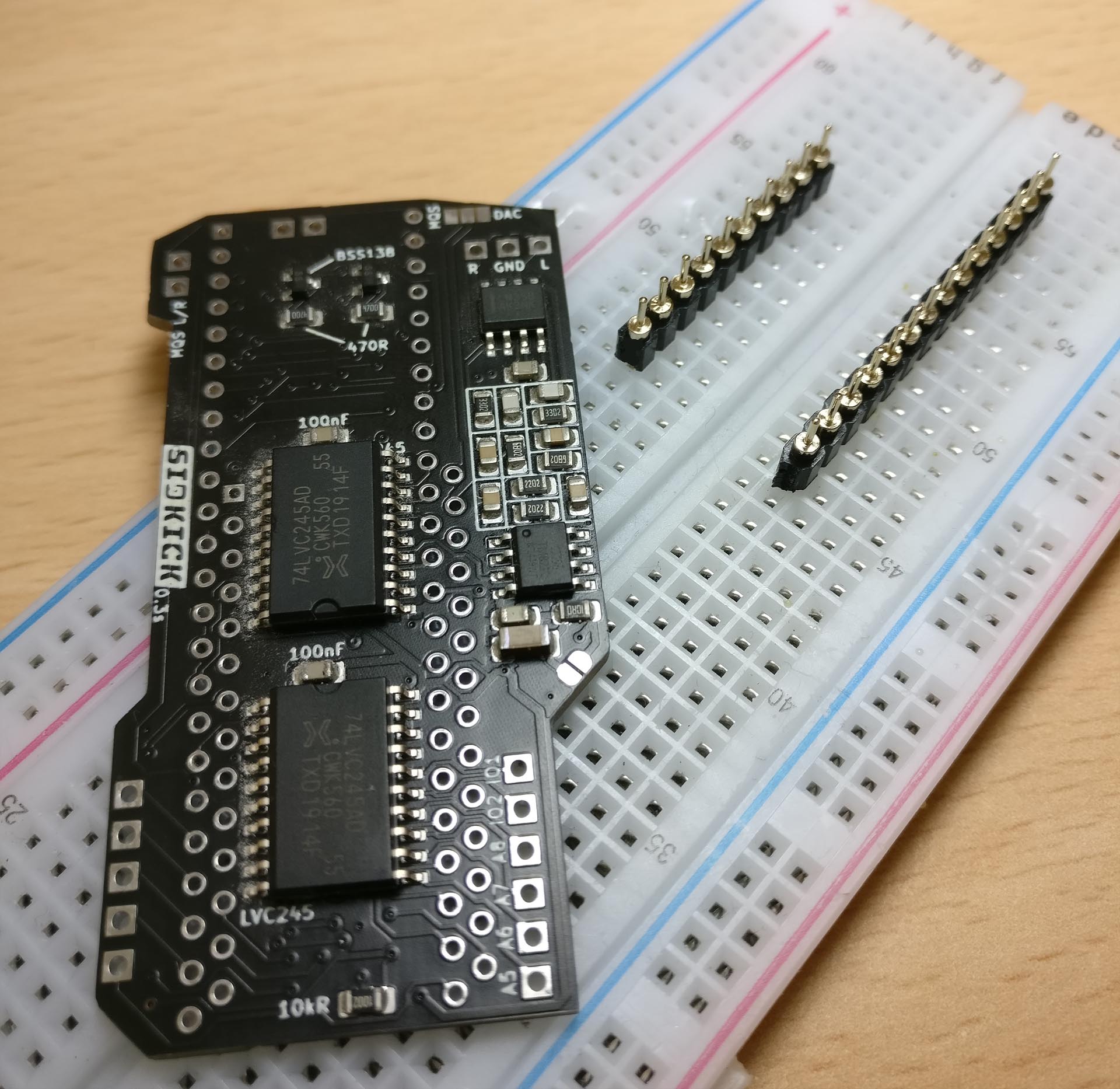
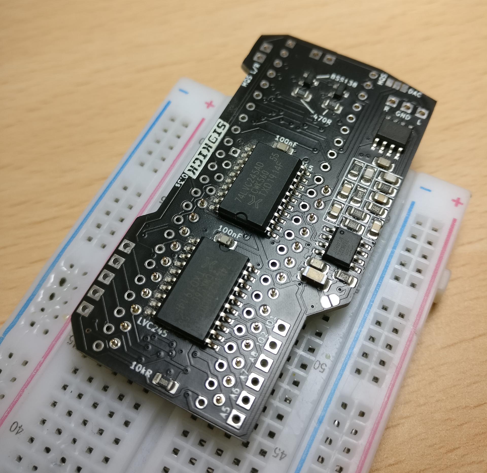
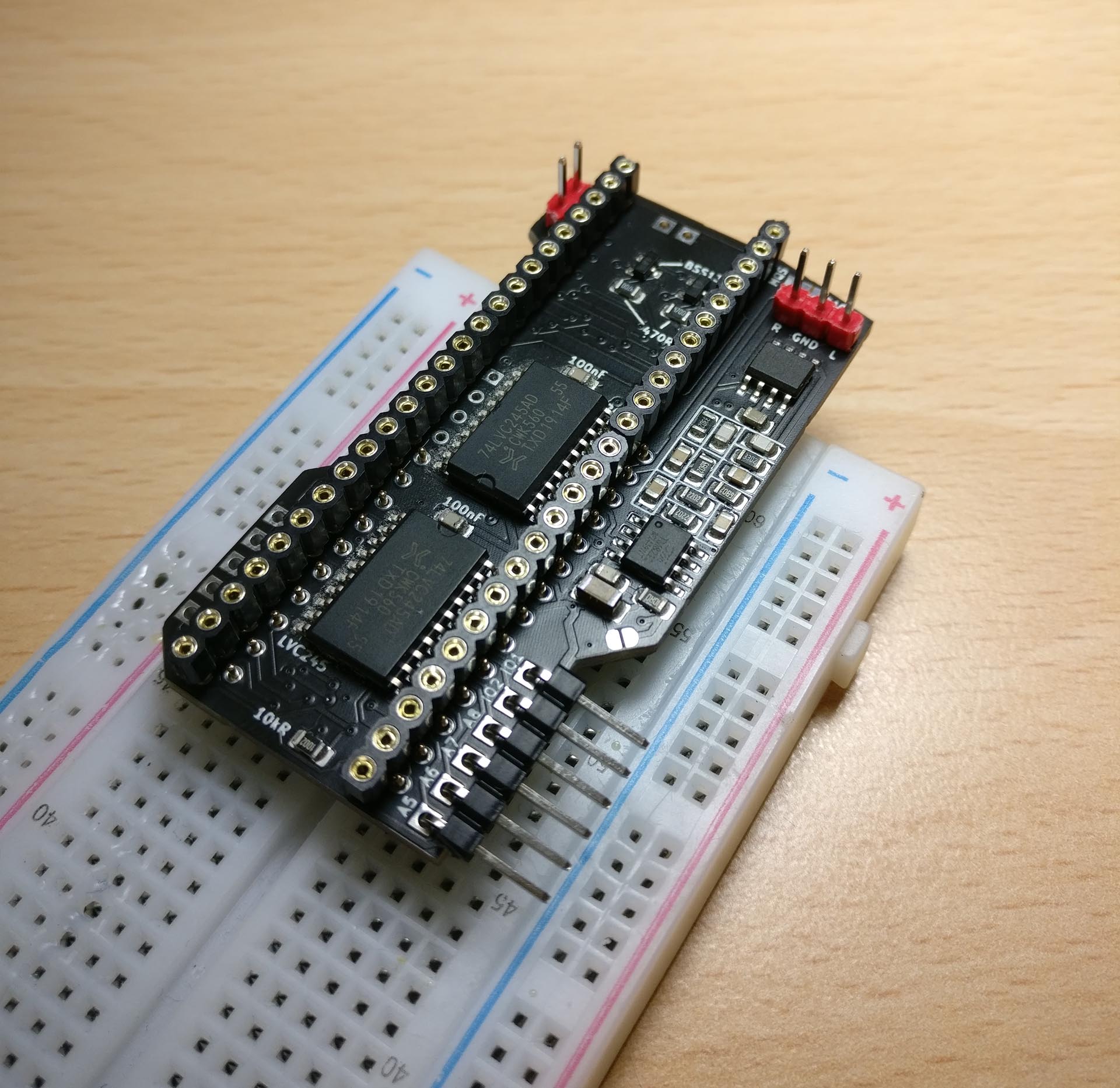
The first step when building the SIDKick is soldering the surface-mount components (top side first). Next solder the pin header for the SID-socket on the bottom of the PCB. I recommend to put them into a breadboard to properly align and hold them in place (as you can see on the image 4 pins on the left side can be left out). After soldering the pin headers, cut the protruding tips. Lastly, solder the socket for the Teensy (again, fixate the pin connector strips to align them) and the connectors for DAC and/or MQS output, address/IO lines and (optional) extension header.
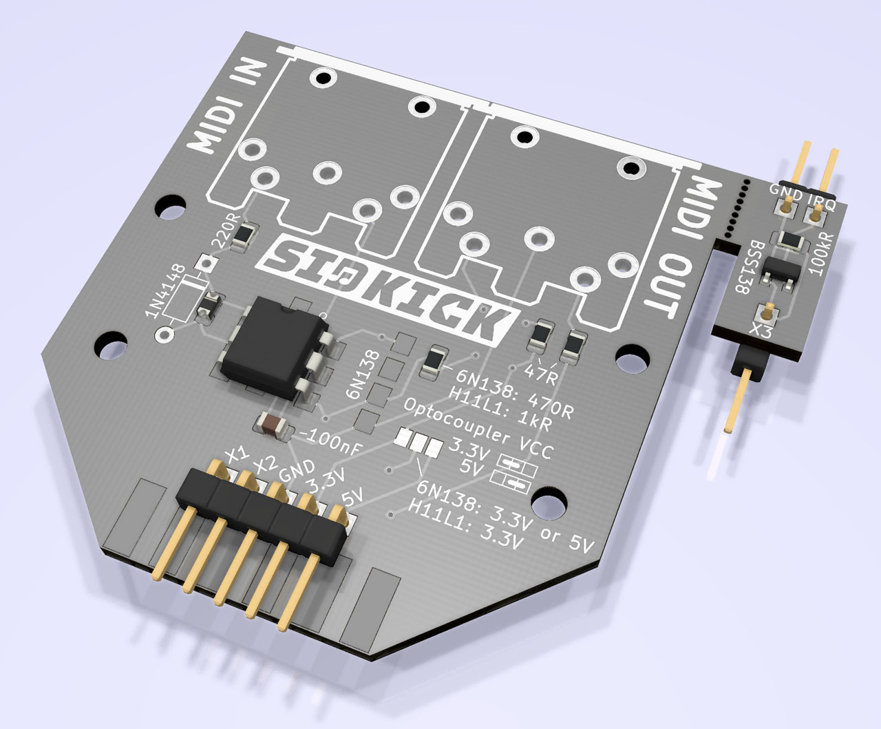
The MIDI-breakout PCB consists of two parts: the actual breakout, and a very small "IRQ"-PCB which is installed inside the C64/C128. I recommend to break/cut the two pieces apart before beginning the assembly. The breakout requires an optocoupler (H11L1 or 6N138) for the MIDI-in circuitry, and only few additional standard components. It follows the schematics provided for Teensy-MIDI and mt32-pi. Pay attention to the different resistor values depending on whether a H11L1 or 6N138 is used (printed on the PCB). You have to choose the voltage for the optocoupler by closing the solder jumper: the H11L1 runs at 3.3V, for the 6N138 you can use 3.3V (out of specs, but normally works) or 5.0V. In my tests either optocoupler/voltage worked fine.
The BOM and assembly information is here. Note, the edge connector is not required (nor connected to anything) and only meant to provide means to firmly attach the breakout, e.g. to the tape or user port.
For LED-stripes there is nothing to build, see the install-options below.
Pay attention to correctly orient and insert the Teensy and the SIDKick (see backside of PCB for markings) into the SID-socket of your C64 or C128. The installation procedure is the same for PAL or NTSC C64/C128 as, starting with version 0.2, the SIDKick-firmware auto-detects what system it is running on.
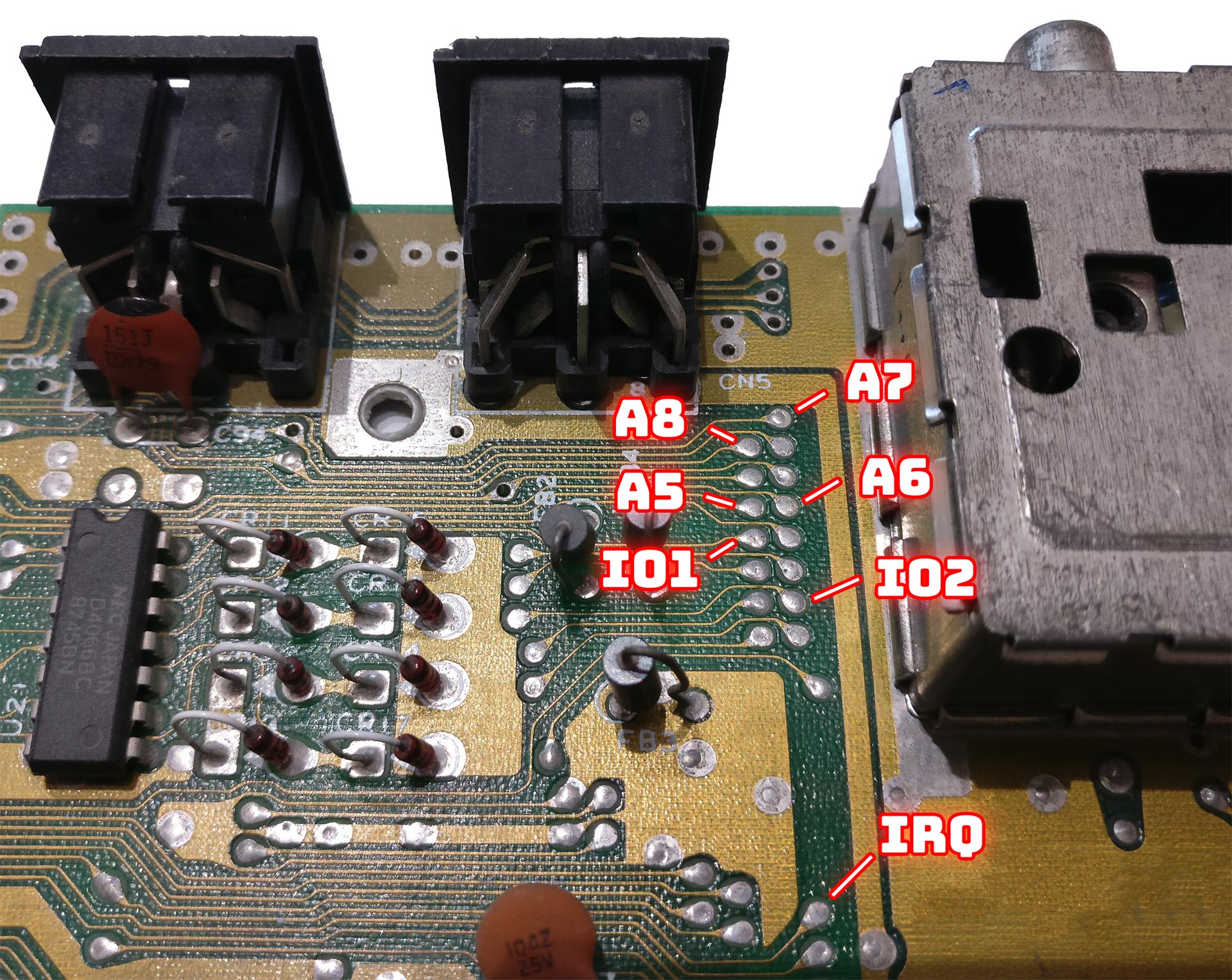
You can choose to emulate a single SID only. If you want to use a second SID, MIDI, or FM emulation, you need to connect additional cables to get the signals to the SIDKick as they are not available at the SID socket:
| SIDKick pin | C64 (see images for alternative locations) |
|---|---|
| A5 | CPU Pin 12 (required for $d420 and FM) |
| A6 | CPU Pin 13 (required for FM) |
| A7 | CPU Pin 14 (optional) |
| A8 | CPU Pin 15 (required for $d500) |
| IO1/2 | expansion port pin 7 and 10 $de00 and $df00 addresses |
| SIDKick pin | C128 |
|---|---|
| A5 | CPU Pin 12 (required for $d420 and FM) |
| A6 | CPU Pin 13 (required for FM) |
| A7 | MMU (U7, MOS 8722) pin 47 (required for $d500) |
| A8 | U3 pin 14 (required for $d500) |
| IO1/2 | expansion port pin 7 and 10 $de00 and $df00 addresses |
The photographs show various (other) locations where these signals can be tapped, e.g. A5 to A8 and IOx are conveniently available on some mainboards (see photo of ASSY 250469) and at the ROMs (not shown on the photos: on the 250469 at the kernal ROM 251913 at pin 5 and 29, for example).
The built-in configuration tool displays which cables have been (properly) installed and restricts the options (e.g. SID-addresses) to the available ones.
You need to choose how to output the sound. You can either use the solder jumper (labelled "MQS DAC" and connect the left-center or center-right to route mono-audio through the mainboard. The better option is to take the stereo output from the pins labelled R GND L (for DAC) or MQS L/R and GND (for MQS). Note that you need to choose the corresponding firmware version which outputs sound to either MQS or DAC.
In principle you can power the Teensy from USB, but the USB-connection is only needed and recommended for development. SIDKick can be powered from the main board by either closing the solder-jumper or the pin-jumper (close to Teensy pin 1) on the bottom side of the PCB.
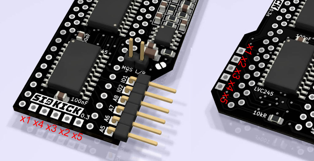
The SIDKick-extension pins are meant for providing features beyond a mere SID/FM-emulation. At the time of writing this is a MIDI-breakout, RGB-LED-stripe control, and a profile-change button. On the SIDKick v0.4(s) PCBs the extension pins (3.3V, GND, X1 to X5) are labelled on the silk screen. The image on the right shows the position of X1 to X5 for the SIDKick v0.3(s) PCBs.
The MIDI-breakout PCB consists of the main part with the two DIN sockets (female, 5 pins, layout: 180°, angled 90°, THT), and the small "IRQ-PCB" with one transistor and one resistor. The two have to be cut apart, the latter has to be installed inside the computer.
The MIDI-breakout is connected using 4 (or 5 when the 6N138 is powered from 5V) wires. Simply connect X1, X2, GND, 3.3V to the SIDKick, and take 5V if required from the C64/C128 board. If you're using a SIDKick v0.3/v0.3s you will have to grab 3.3V from the SIDKick-PCB (Teensy Pin 46) or generate it from 5V, which is available at many places on a C64/C128 mainboard, e.g. using a LM1117 voltage regulator with 3.3V output or a generic "step-down converter".
The "IRQ"-PCB is connected to X3 on the SIDKick and to GND, which can be found at the expansion port (see image above). For the emulation of Datel/Sequential-MIDI-interfaces the IRQ-pin is connected to the IRQ-line of the C64/C128 (also at the expansion port and on the mainboard). In case of Namesoft-emulation connect the IRQ-pin to the NMI-line which can also be found at the expansion port (but hard to reach) or at the CPU (e.g. pin 4 of 6510/8500 or one of the CIA 6526). I recommend using the Datel/Sequential option which seems to have better software support.
Lacking a MIDI-Synthesizer? It is very easy to try out mt32-pi together with SIDKick: the MIDI-breakout also works with mt32-pi! Simply connect it this way:
| MIDI-Breakout | Raspberry Pi with mt32-pi |
|---|---|
| X1 | GPIO 16 (Pin 10) |
| GND | Ground (Pin 6) |
| 3.3V | 3.3V (Pin 1) |
| 5V (if needed) | 5V (Pin 2) |
The SIDKick can control up to 32x WS2812b-LEDs. Attention: these LEDs can draw quite some current (the LED-stripes I tested ran at about 220mA max a typical settings which should be no problem for a decent power adapter). Make sure that your power supply can handle it, or use an extra one for the LEDs and don't forget to connect ground lines then.
These LED-stripes typically require 5V (3.5V to 5.3V according to the data sheet; 5V can be found at various places on the C64/C128 board), GND, and one data line, which is X4 on the SIDKick. Note that the WS2812b logic levels require 0.7*(supply voltage). You might be lucky directly connecting X4 to the data line of the LED-stripe (in fact, it worked for all LED-stripes I tested). If not, you can choose one of the options described here, or use a simple prebuild level shifter as shown on the right side.
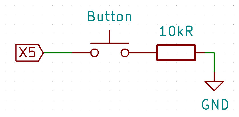
The X5-connector is used to read a push button for switching profiles (short pressing: next profile, long pressing: previous profile). You can add a button which pulls this line using a pull-down resistor (e.g. 10kOhm) to ground. When changing profiles the SIDKick will output SAM voice with the volume specified in the new active profile.
The SIDKick-PCBs do not need to be programmed in any way. Only the Teensy needs to be flashed with pre-built binaries (available in the release package) using the Teensyloader tool.
IMPORTANT: To upload the firmware you need to connect the Teensy to your PC using USB. If the SIDKick is already installed in your computer you must not close the power-from-mainboard jumper (solder-jumper/pin-jumper close to Teensy pin 1) and connect USB at the same time – unless you followed these instructions.
NOTE: Prior to flashing the actual firmware for the first time (or updating to a new firmware version), run the EEPROM-eraser tool (SIDKickEEPROM.hex). It initializes the SIDKick-configuration stored in the EEPROM of the Teensy. Uninitialized EEPROM data may prevent the SIDKick from working, in particular launching the configuration tool.
I made a very simple (and not very comfortable to use) command-line tool to patch the firmware-hex-file prior to uploading. Patching is required if you want to add PRGs to the menu launcher. I provide a batch file for Windows, a script for Linux users, and an example PRG-list. Upload the patched firmware afterwards using the Teensyloader.
- flash and run SIDKickEEPROM
- optional: patch SIDKick firmware
- flash SIDKick firmware
- install SIDKick into your Commodore
If you're using Sidekick64 then you should update to firmware 0.48 and afterwards overwrite the Sidekick64-files on the SD-card which are included in the SIDKick-release package.
The built-in configuration tool provides 10 slots to store different profiles. The settings are hopefully mostly self-explanatory (selecting SID types, addresses etc.) and commands are listed on a help page (F1). Here I focus on one aspect that deserves explanation: possible conflicts with other hardware attached to your C64/C128! These conflicts are not specific to the SIDKick, they would also exist with the hardware it emulates.
The SFX Sound Expander emulation uses the IO2-address space ($df00 to $dfff) which might also be claimed by cartridges at the expansion port, e.g. the EasyFlash 3, GeoRAM, REU, freezers. The SIDKick can operate in "passive mode", i.e. it listens to the communication on the bus, but does not write to it. This way no harm is done to any device, but programs will not be able to auto-detect the presence of the SFX Sound Expander, and (yet unlikely) the SFX emulation might produce garbage sound if data meant for the other device is written.
The MIDI interfaces (configured in the "extensions" section of each profile) for the C64/C128 use parts the IO1-address space ($de00 to $de07) and again this might conflict with cartridges. When the option "MIDI-in enabled" is set to "off" then only the MIDI output is active (this requires only non-critical listening to the data on the bus), but MIDI-input and reading (e.g., for auto detection) from the emulated device is omitted.
To avoid bus conflicts when you use cartridges operating in the IO1/2 address spaces, make sure you disable SFX and/or MIDI-in. Note that the Sidekick64-cartridge autodetects an installed SIDKick and avoids conflicts during browsing, program launching etc., but when it emulates an Easyflash cartridge, for example, conflicts are expected as with real hardware.
The firmware is built with Teensyduino (I used Arduino 1.8.13 and Teensyduino 1.53, alternatively it can also be built with PlatformIO). Note that there are three defines in the code (globals.h and incl_resid.h) which need to be set properly:
- when compiling the firmware for C128: #define FIRMWARE_C128
- choosing the output (MQS vs. DAC): #define audioDevice
- set folder where you store the SIDKick project: #define SIDKICK_SOURCE_DIR
The compile settings are: "Board: Teensy 4.1", "CPU-Speed: 816 MHz", and "Optimize: Fastest". You may also choose a lower clock frequency of 600 MHz or 720 MHz as long as you adjust TEENSY_CLOCK in the code accordingly. During most tests SIDKick was running at 816 MHz (at lower speeds the emulation might resort to being less cycle exact or produce glitches). You can upload the firmware(s) directly from the Arduino IDE or use the Teensyloader to flash hex-files (don't forget to not power your C64/C128 from USB).
The handling of the communication and emulation is very similar to that in my Sidekick64-project and earlier experiments (e.g. on paddle/mouse handling) in this framework.
As mentioned above, SIDKick is using reSID 0.16/1.0 and fmOPL. While reSID 0.16 and fmOPL work "out of the box", the original reSID 1.0 does not: it initializes its filter emulation by precomputing lookup tables not only taking too long for instant-on, but more importantly exceeding the Teensy’s available memory. I have modified reSID 1.0 to work with offline-precomputed tables which can be stored in the flash memory of the Teensy (and some other optimizations, partly activated in the current version).
I also had to modify the Teensy audio library to provide a polling-like mode: the reason being that the communication with the C64/C128 is handled by an interrupt with is triggered every clock cycle – and this conflicts with the standard handling of audio output.
The Teensy handles all timing-critical communication protocols, i.e. C64/C128 bus, MIDI serial and WS2812 via bit banging to achieve high flexibility and best possible robustness. This, however, does consume some CPU cycles and likewise does the emulation, in particular reSID 1.0. As the bus timings (especially on the C128) are a bit more "wasteful" from a software emulation perspective, the SIDKick might not be able to emulate two (active!) 6581 with reSID 1.0 and FM synthesis at the same time (I'm not aware of real uses cases, except for reSID 1.0-SID-pseudo stereo plus FM, but well...). I decided to leave this responsibility to the user: for example, you can define a profile without pseudo stereo for such demos, or resort to reSID 0.16. Note, when the second SID or FM is not used by a program, the respective part of the emulation is inactive. Further optimization is left for future work ;-)
Be careful not to damage your Teensy, PC, or Commodore, or anything attached to it. I am not responsible if you or your hardware gets damaged. Keep in mind that the Teensy is typically overclocked. If you don't know what you're doing, better don't... use everything at your own risk.
My portions of the source code are work licensed under GPLv3. The PCBs are work licensed under a Creative Commons Attribution-NonCommercial-ShareAlike 4.0 International License.
Last but not least I would like to thank a few people and give proper credits: toms01 for making me start this project and lots of early testing; emulaThor for extensive testing and valuable bug reports and feedback. androSID for donating a NTSC-VIC II and hinting to the opamp; Crisp for borrowing me a C64-MIDI interface and synthesizer to trigger the development of MIDI-support; Retrofan for designing the SIDKick-logo and his font which is used in the configuration tool; Flex/Artline Designs for letting me use his music in the config tool; bigby for more testing of the first version. And of course, the authors of reSID and the OPL emulation.
There have been previous attempts of making drop-in replacements based on a Teensy which deserve being mentioned, e.g. Teensy-reSID and 6581-SID-teensy. However, both are far from a complete replacement, and, for various reasons, were not suitable as a basis for SIDKick.
Thanks for reading until the very end. I'd be happy to hear from you if you decide to build your own SIDKick!
Teensy is a trademark of PJRC.COM LLC.
