An arduino-based oxygen analyzer for EANx/Nitrox diving gases.

There are many plans and schematics for Nitrox analyzers available online. This project is an attempt to build a compact and neat device, inspired by the main characteristics of these designs, including:
- Bright OLED display
- Simple user interface using a rotary encoder
- Automatic MOD calculation for most common O2 partial pressures (1.4, 1.5 and 1.6bar)
- Automatic calibration
- Li-Ion battery, rechargeable using a micro-USB phone charger
- Sound feedback
- Custom PCB mounted for increased reliability and more polished look
- PlatformIO
- Arduino Framework
- U8g2
- ClickEncoder
- TimerOne
- KiCad
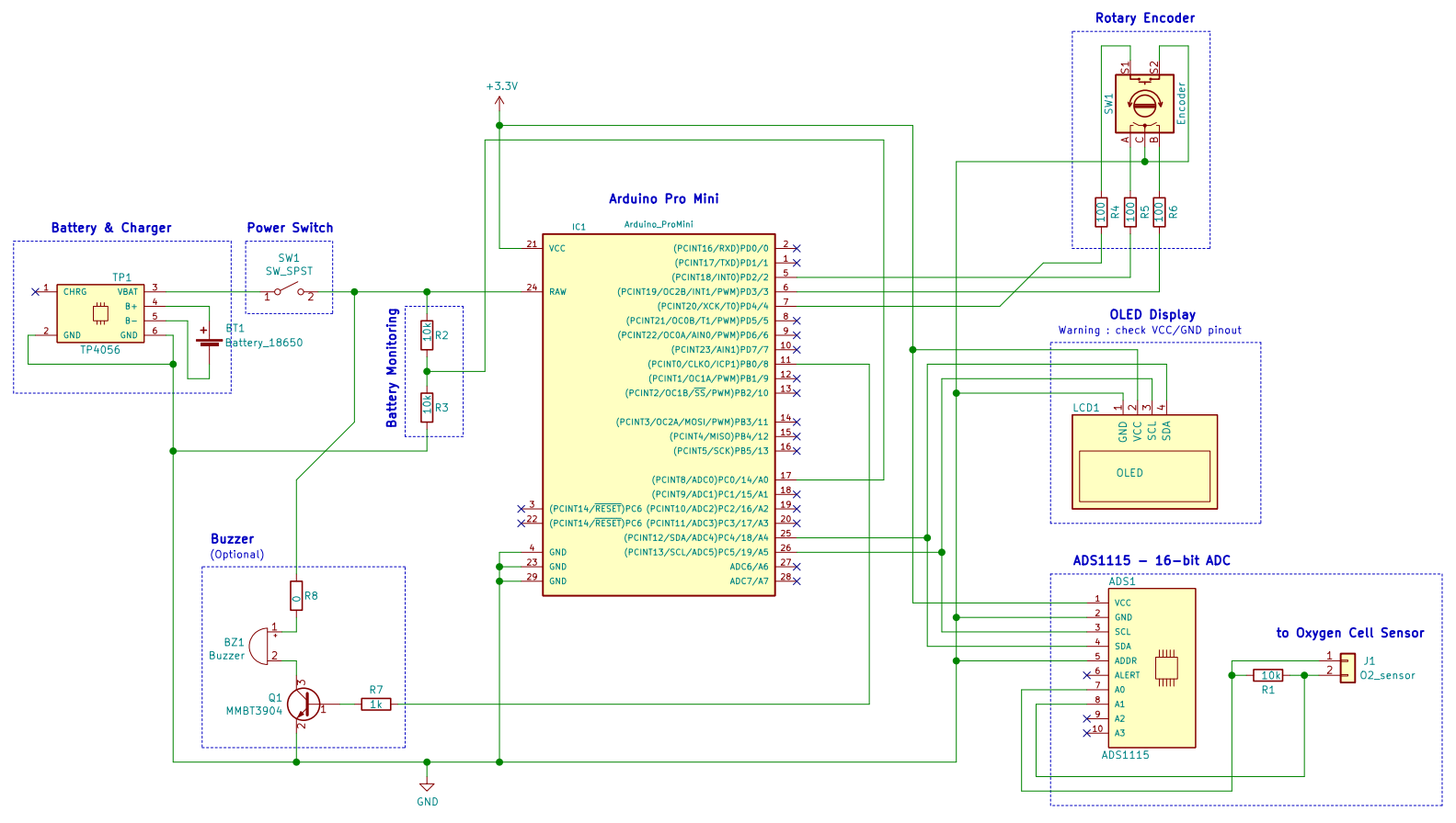
This analyzer is based on classical and cheap components, they can be sourced for <20€ (oxygen cell excluded):
| Component | Quantity | Comment |
|---|---|---|
| Arduino pro mini 3.3V/8MHz | 1 | 3.3V version has been chosen for its ability to run on a single 3.7V Li-ion battery |
| ADS1115 | 1 | 16-bit ADC with PGA over I²C, using gain of 16x provides a 7.812µV resolution |
| OLED 1.3" I²C | 1 | Cheap but very readable OLED display. WARNING: depending on the model, VCC/GND pinout can be inverted |
| Rotary encoder with switch | 1 | |
| TP4056 Battery charger | 1 | Choose the version with protection IC (has 6 connection pads) |
| 18650 Li-ion battery | 1 | Any other battery providing > 3.5V should be Ok, adjust battery monitoring divider accordingly |
| Power switch | 1 | Simple SPST should suffice |
| Passive buzzer | 1 | |
| Resistor 100Ω | 3 | |
| Resistor 1kΩ | 1 | For buzzer drive circuit |
| Resistor 10kΩ | 3 | For sensor load resistor and battery monitoring divider |
| NPN transistor (e.g. 2N2222) | 1 | For buzzer drive circuit |
| Connector to O2 cell | 1 | Choose the type adapted for your cell |
| O2 Cell sensor | 1 | You can use CCR cells |
Because the Pro Mini does not integrate a USB interface, you have to use a USB to UART breakout adapter (typically FTDI ft232) in order to program the chip. This can also be sourced for ~2€. Make sure to set the jumper on the 3.3V position.
The analyzer can be assembled by hand-wiring the components, or by soldering them on a PCB.
A detailled BOM for the PCB is available in the project pcb folder.
See the open issues for a list of proposed features (and known issues).
Copyright © 2020 Charles Fourneau
Distributed under the MIT License. See LICENSE for more information.
- U8g2
- ClickEncoder by Dennis
- TimerOne
- Adafruit_ADS1X15
- and many others...