Dutch SKies - A Mixed Reality view of air traffic over The Netherlands (and elsewhere)
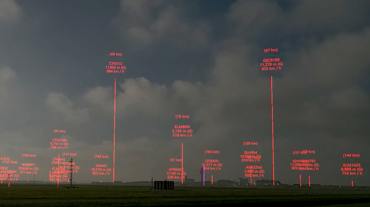
This application, for Microsoft HoloLens 2, provides a real-time view of air traffic in mixed reality (MR), through the data provided by the OpenSky Network. It provides both a map view of air traffic, as well as a live view of traffic in the sky. The image above is a view of Amsterdam Schiphol Airport (the main control tower is next to the purple line). Over a dozen aircraft are shown in the MR overlay, with some of their flight statistics, such as call-sign, altitude, speed and distance from the viewer. For the top two flights the (real) contrails can be seen between the lines of text, indicating a fairly good alignment of the mixed reality overlay with physical reality.
Background
DutchSKies was created as an entry for the Mixed Reality Challenge: StereoKit (C# and OpenXR), using the excellent StereoKit framework. It serves mostly as a proof-of-concept, and demonstration of mixed reality.
Dutch SKies is Copyright (C) 2021 Paul Melis, SURF (paul.melis@surf.nl). See the section below for details on the license under which is it made available.
Use cases and benefits
Using this 3D mixed reality view air traffic patterns and spatial relations can be more intuitively inspected, more so than when looking at the same data on a computer monitor. The overlay of real-time flight data over the actual flights can help even further.
In principle, the application could be used for other types of spatial data, as long as it can be represented both on a map and in the mixed reality overlay. This currently isn't the focus, but should not be too hard to add.
Examples
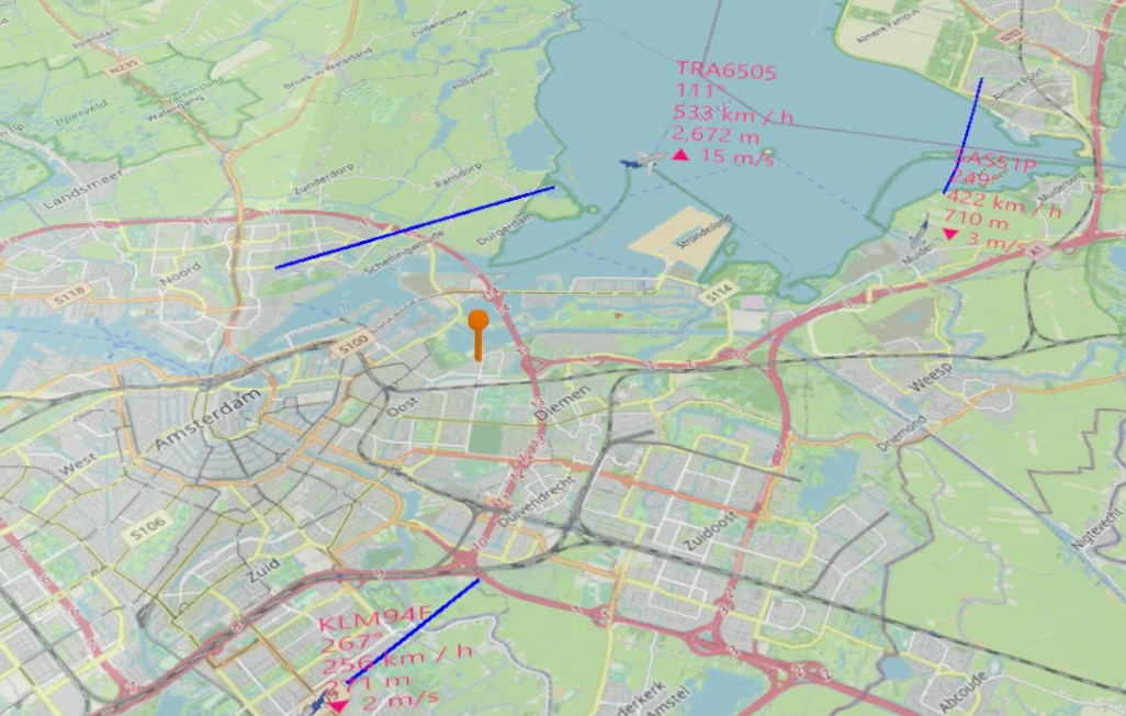
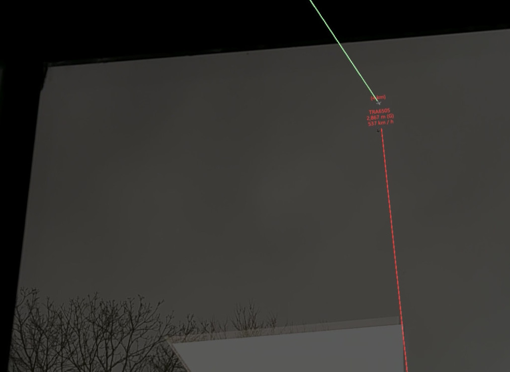
Below is an example with on the left a map view of air traffic around Amsterdam, as seen through the HoloLens 2. A flight with call-sign TRA6505 that has just passed over the observer's location on the Amsterdam Science Park (marked with the orange pin), and is climbing away. On the right, looking out the window TRA6505 is indeed close to the mixed reality projection of where the plane is expected to be:
| Map view | Sky view |
|---|---|
 |
 |
Map view
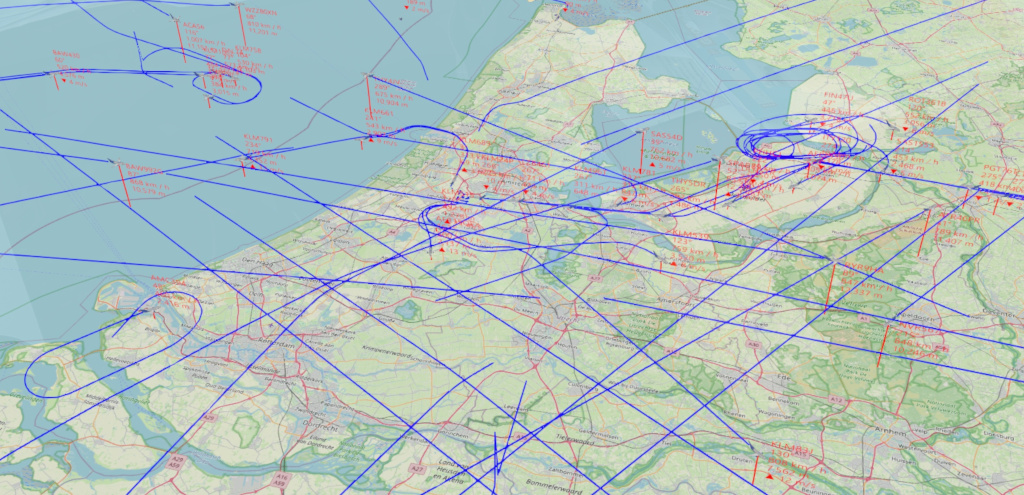
Apart from augmenting real air traffic with a mixer reality overlay, the map view can used to visually inspect air traffic patterns and relations that are otherwise hard to detect and/or grasp.
Here are plane tracks (in blue) on a windy day. Apparently, quite a few holding patterns where used to properly guide planes towards Amsterdam Schiphol Airport (which is roughly at the center of the image):
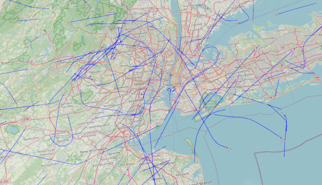
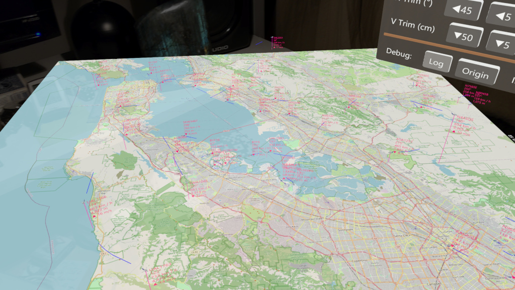
The application isn't limited to traffic over The Netherlands. Your own maps and areas can be configured at will. For example, here is a view of the very busy airspace surrounding New York:
Requirements
DutchSKies is not available on the Microsoft Store, but might get an entry there are some point. Until then, you will need to build the application yourself, if you want to try it.
In order to build it you will need:
- Visual Studio, set up for Windows UWP development, with these two packages installed (through NuGet):
- StereoKit (developed and tested with 0.3.4)
- Microsoft.MixedReality.QR
- Python 3, in case you want to run some of the scripts under
Scripts. Modules used by the scripts are
In order to test Dutch SKies in mixed reality you will need a Microsoft HoloLens 2.
Disclaimers
Dutch SKies has not been tested outside of Amsterdam, The Netherlands. So with different geographical locations some bugs will probably surface :) I'm especially curious if it works without issues on the Southern Hemisphere when using a custom map or sky-mode location (see below).
This application has only been tested with a Microsoft HoloLens 2. It might also work on other devices. Running it in StereoKit desktop mode also works, of course, but that does not really provide the full experience.
OpenSky Network real-time data
Note that this application makes use of the OpenSky Network as a real-time data provider. As such, when using this application, you are bound to its General Terms of Use & Data License Agreement.
How to use a custom map
By default, only Amsterdam and Schiphol and Eindhoven airports are included as (hard-coded) maps. The Dutch sky is relatively busy with planes, including ones crossing from/to overseas, others landing at airports nearby the country, etc. So this should provide some interesting views out-of-the-box for a country-scale airspace. But you might want to view a different area yourself, of course.
You will need 3 things to use a custom map/sky view:
-
A JSON configuration file describing the map extent, map image, observer location, etc. You can also include a number of landmarks to fine-tune the alignment of the MR world with the real world.
-
An online place to host the JSON configuration file from step 1, and any used map images. This can be anywhere (a Google Drive, your own server, etc), as long as you can provide a URL to the JSON file that is accessible by the HoloLens on on which you plan to run Dutch SKies.
-
A QR code that contains the URL from step 2. You can use
Scripts/text2qrcode.pyto generate a PNG image holding the QR code for a given URL. You do not have to print this QR code image, but it does need to be visible in sufficient size for the HoloLens to be able to scan it successfully. The Microsoft docs suggest at least 5x5 cm, but that seems a bit small. Showing the image full-screen on your monitor will allow the HoloLens to scan the QR code, even when it's some distance away.Note that StereoKit can take advantage of the QR code's orientation, but this currently isn't used in Dutch SKies.
By using the QR code only for providing the URL to the actual configuration allows you to update that configuration without having to update the QR code.
See the Example directory for files corresponding to the examples below.
Using a map tile service
As an example, let's create a configuration for the San Francisco Bay area, where there are lots of airports.
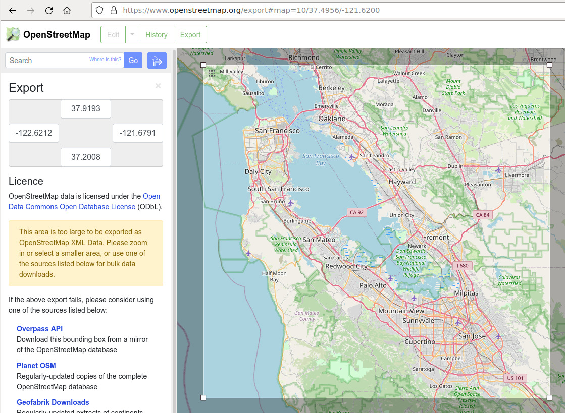
On https://www. openstreetmap.org we navigate to the San Francisco area,
then use the Export button in the top row. On the left you can see the lat/lon extent for the current view.
You can also choose Manually select a different area just below the extent numbers (not visible in the screenshot as it already
has been selected) to more precisely select the extent of our map:
The next step is to create the configuration JSON file. We specify the lat/lon range and other map data involved, plus specify the server addresses where to fetch tiles (in this case from official OpenStreetMap tile servers):
{
    "map_sets": [
        {
            "id": "SF Bay Area",
            "items": [
                {
                    "id": "SF Bay Area",
                    "lat_range": [37.2008, 37.9193],
                    "lon_range": [-122.6212, -121.6791],
                    "image_source": {
                        "type": "tile_server",
                        "id": "osm-official"
                    },
                    "zoom": 12
                }
            ],
            "tile_servers": [
                {
                    "id": "osm-official",
                    "type": "osm",
                    "urls": [
                        "http://a.tile.openstreetmap.org/{zoom}/{x}/{y}.png",
                        "http://b.tile.openstreetmap.org/{zoom}/{x}/{y}.png",
                        "http://c.tile.openstreetmap.org/{zoom}/{x}/{y}.png"
                    ]
                }
            ]
        }
    ]
}
Note that there are several different tile servers that can be used as alternatives, see here.
Also note that for the official openstreetmap.org servers there is a Tile Usage Policy.
Finally, see the relevant FAQ entry below on why these tile server addresses are not hard-coded in the application.
The map_sets section can list one or more maps, which can be switched in the application.
Next, we upload this JSON file to a location where the Dutch SKies app can retrieve it. We then generate a QR code for this URL,
display it on a PC screen (or print to paper) and use the Scan QR code button in the app UI to initiate scanning. As soon as a QR code is recognized
the scan function is disabled (notified by the button release sound) and the configuration will get loaded. In the process the map
geometry (initially all grey) and extent are updated, and the process of retrieving the necessary image tiles is started. Once all tiles are retrieved
the map will be updated to show the image.
If everything goes right, you should see this after at most half a minute:
If anything goes wrong in this workflow then you can check the Log window for warnings/errors.
The JSON configuration data retrieved by scanning a QR code is stored on the device and will be available the next time the application is started. To update a stored configuration simply scan a QR code with JSON data that holds the same map_set ID. This will overwrite the existing stored configuration.
Tile naming scheme
The current implementation is geared towards the tile naming scheme used by OpenStreetMap (x, y, zoom, 256x256 pixels).
Using a static map image
Instead of dynamically fetching tiles it is also possible to use static map image. This has some advantages:
- It is usually faster to load a single image from a source you control, than a bunch of tiles from a service you don't control (or which might change its policies, price, etc)
- You can use custom map imagery, not found in public services
- You can easily add content to the map image in any way you like (e.g. annotations)
As an example, we'll generate a map image and relevant meta-data based for the San Francisco case shown above.
For this, we'll use the Script/make_osm_map.py script which retrieves the necessary tiles and pastes them
together in a single image.
We use the extent listed above as arguments to make_osm_map.py. The one extra value we need is the
zoom level, which determines the resolution of the output image. The current value is part of the URL, e.g.
the 10 in ...#map=10/37.4956/.... At the current zoom level (based on the resolution of the browser window)
the map would be a bit in resolution, so we increase the zoom level a bit. At zoom level 11 the resulting map
covers 6x6 tiles and is 1536x1536 pixels, at zoom level 12 it covers 12x11 tiles and is 3,072x2816 pixels.
Here, we use zoom level 12:
$ ./make_osm_map.py 37.2008 37.9193 -122.6212 -121.6791 12 sanfrancisco
tile range: i = 652-663, j = 1581-1591
map range:  37.160316546736766 -122.6953125 -> 37.92686760148134 -121.640625
center:  37.54359207410906 -122.16796875
Map size at center = 93.070 x 85.332 km
Retrieving 12 x 11 tiles
(652,1581) (653,1581) (654,1581) (655,1581) ...
Writing output image sanfrancisco.png ... done

$ ls -l sanfrancisco.png
-rw-r--r-- 1 melis users 6808172 Dec  3 21:27 sanfrancisco.png

$ ls -l sanfrancisco.png.json
-rw-r--r-- 1 melis users 280 Dec  3 21:27 sanfrancisco.png.json

$ cat sanfrancisco.png.json
{
    "image_source": {
        "type": "url",
        "url": "sanfrancisco.png"
    },
    "lat_range": [
        37.160316546736766,
        37.92686760148134
    ],
    "lon_range": [
        -122.6953125,
        -121.640625
    ],
    "name": "sanfrancisco",
    "zoom": 12
}
Two files are created, the map image (sanfrancisco.png) and a JSON file holding metadata (sanfrancisco.png.json).
Note that the actual lat/lon range of the map image is larger than what we specified. This is expected, as only full image tiles are used to cover
the input lat/lon, without clipping the tiles.
The JSON file produced next to the image can be used to set up the necessary configuration JSON file, as shown earlier:
{
    "map_sets": [
        {
            "id": "SF Bay Area",
            "items": [
                {
                    "id": "San Franciso",
                    "image_source": {
                        "type": "url",
                        "url": "/sanfrancisco.png"
                    },
                    "lat_range": [
                        37.160316546736766,
                        37.92686760148134
                    ],
                    "lon_range": [
                        -122.6953125,
                        -121.640625
                    ]
                }
            ]
        }
    ]
}
Note that if the url field does not start with http:// or https:// it is assumed to be a path relative to the URL from which the configuration file
was retrieved.
Projection
Any map image needs to adhere to the EPSG:3857 projection (also known as Web Mercator). This is the projection used by OpenStreetMap, Google Maps and many others to match WGS84/EPSG:4326 (basically GPS coordinates) with Web Mercator.
It is crucial that you that the WGS84 latitude/longitude map extent matches the given map image, other plane locations won't be correct.
How to use a custom observer location
For getting a correct sky view of the planes you will need to set an observer location. Plus, for fine-tuning the alignment of the mixed reality view with the real world it can be very useful to specify a number of landmarks. The latter can be edges of high buildings, chimneys, church spires, mountain peaks, etc. Preferably something that stands out in the environment over which you can easily align a marker line.
For both observers and landmarks you can specify a set of items. Within the the application you can then select the set you to use. You specify each observer and landmark item like this:
    ...

    "observer_sets": [
        {
            "id": "Amsterdam Science Park",
            "items": [
                {
                    "id": "Office (floor @ desk)",
                    "lat": 52.3...,
                    "lon": 4.9...,
                    "alt": 0.39
                }
            ]
        }
    ],


    "landmark_sets": [
        {
            "id": "Amsterdam Science Park",
            "items": [
                {
                    "id": "Tall building left edge",
                    "lat": 52.3....,
                    "lon": 4.9...,
                    "topalt": 68,
                    "botalt": -4
                },
                {
                    "id": "Tall building right edge",
                    "lat": 52.3....,
                    "lon": 4.9....,
                    "topalt": 68,
                    "botalt": -4
                },
                {
                    "id": "Low building roof",
                    "lat": 52.3...,
                    "lon": 4.9...,
                    "topalt": 10.59,
                    "botalt": 0.39
                }
            ]
        }
    ]

    ...
To get the lat/lon values, Google Maps, OpenStreetMaps and other similar services provide a function in their web UIs to query the location values for a particular position on the map. A GPS receiver can be another source of values, including altitude. Note that the altitudes are interpreted to be WGS84 (e.g. GPS) altitudes in meters above sea level. You can estimate them if you don't have good values and still rely on the position of the vertical lines for trimming the view.
You can either include these extra sections in the JSON configuration file holding the map (as shown earlier), or store each section (or both) in a separate JSON file. Whenever a QR code is scanned the corresponding JSON file is retrieved and any sections in it applied to the current scene. The configuration data from the JSON file is also stored on the device, so can be reused later on.
Whenever landmarks are loaded the button Landmarks in the UI will list the number of landmarks. When the button is
enabled each landmark will be drawn as a vertical line with the ID of the landmark. In general, the alignment, especially
with respect to North, will be off substantially. On the main UI window there's a button Trim, which
opens a window for trimming both horizontal rotation and vertical translation. Use these trimming buttons to get
the overlay of the landmark lines in the right place.
Note that the Trim window will stay close to the observer position currently set (the wind rose on the floor), and will relocate in discrete steps based on head position. The reason for this is to not have to manually drag the window around while aligning landmarks that surround you, but also not to tie it directly to the head position and orientation (as the latter makes it harder to use). The current UX choice isn't perfect, so might get revisited at some point.
Known issues and bugs
-
The device position and orientation at application startup is taken as the mixed reality world origin and axis, with the view direction assumed to be North. The map is placed slightly in front and below of this origin. There currently is no functionality to move the map, other than restarting (this only applies to the map, the sky view can, and usually needs to, be trimmed, as described above).
-
The JSON parsing isn't fully robust currently, either to syntax errors in the JSON data itself, nor to fields/values that are expected, but missing.
-
The map surface always represents an altitude of 0m (sea level), which will look weird for planes landing at airports at much higher altitudes. Having a real 3D map with terrain height would fix that, although the actual visible height above the map is fairly small compared to the map dimensions on most cases (see also FAQ below).
-
When loading a configuration that uses a large map image, the rendering can briefly be interrupted (even with the view going fully black), while the map is processed and uploaded to the GPU. At the moment, there is no easy fix for this.
-
Most of the coordinate math is done in single-precision floating-point, which might be on the edge for what is needed for some of the values (e.g. the EPSG:3857 map coordinates). But since StereoKit's matrix and vector classes are also all single-precision there isn't much to be done about that currently (apart from using double-precision replacement classes).
FAQ
-
Can it be built for VR, e.g. Oculus Quest?
In principle yes, as the code is based mostly on StereoKit, which also supports any OpenXR device, including for VR. But the current project file and solution are tied to UWP as platform. Also, at least the QR code scanning will currently not work on a Quest (and possibly other things as well).
-
The planes seem to be jump a bit every few seconds
The updated plane location data from the OpenSky Network is only retrieved every few seconds. The movement of the virtual planes is currently extrapolated based on the last received data, so might be a little bit off until the next set of data points is retrieved.
An alternative could be to retrieve the last two known data points for each plane and then interpolate the plane path between those, but that would mean plane locations would lag by about 5-10 seconds, which would then not match very well with the actual physical location of the planes.
Also see the next question.
-
The sky-mode virtual planes are not aligned very well with real-world planes!
Yes, this is expected and almost unavoidable, although the virtual overlay can be tweaked to be fairly close to the real planes. It certainly should be accurate enough to track and identify real planes without too much ambiguity.
There are (at least) three reasons for the mismatch:
-
The real-time plane tracking data provided by the OpenSky Network is pretty accurate when it comes to a plane's position, but the timestamp attached to that data point only has a granularity of one second (the
time_positionfield in the REST API). In that one second a fast-flying plane will move quite a bit across the sky. So even though the position is given with precision, the exact moment of when the plane was at that position is not known accurately enough. -
As the data from the OpenSky Network only provides a plane's location at some moment in the past, a prediction needs to be made where the plane is right now, in order to overlay the virtual plane. This prediction isn't currently very good, especially for planes that are changing course and speed a lot (e.g. when making a turn to line up with the runway). The prediction can probably be improved, e.g. using Kalman filtering.
-
Alignment of the Mixed Reality world with the physical world is imprecise. The HoloLens 2 does not have location sensors, although Wifi-based location tracking might be of some use. The manual specification of the current location (using a QR code specifying lat/lon/altitude) can be pretty accurate, and any small deviations from the ground truth in position will not lead to much misalignment.
But setting the orientation of the virtual world with any precision is a bit tricky, and any rotation away from true North will be quite noticeable, as the virtual planes will be either behind or in front of their real planes. Hence, the option to do orientation (and height) trimming through the UI.
-
-
How about including terrain height in the map?
For the case of The Netherlands this doesn't have much value ;-). The highest "mountain" in The Netherlands is 321m high (the Vaalserberg). The lowest point is around 6.74m below sea level. The default map is around 360km wide, shown at 1.5m physical size in the MR world. That translates to 240m of altitude per millimeter of physical (MR) map size. So the height difference for The Netherlands would amount to less than 2 millimeters in MR, not really worth it.
For a different area in the world, or when using a much smaller map of mountainous terrain, it might make more sense to include height, though.
-
Why not use a (3D) terrain service, such as Bing Maps?
Indeed, there is the Stereo Kit Bing Maps sample, although I did not try it, nor looked at the code. The reason is that it requires a Bing Maps API key, plus it would base this code on non-free (and commercial) software. The same would hold for other similar services.
The current setup, based on pre-generated maps, is simple and free to use and customize. It does not need registration, nor an API key. Adding your own maps is fairly easy, see the section above.
-
Why not simply hard-code OpenStreetMap tile downloading in the code? Why the indirection using
tile_serversin the JSON configuration files?Hard-coding the URLs of OSM tile servers in the code is against the OSM Tile Usage Policy, or at least, it's strongly discouraged. And using the JSON file to specify tile servers allows future extensions to use other tile schemes and servers, or to use a local OSM cache (the latter allows much faster tile retrieval during development cycles).
License
All files, except those listed under the Attributions subsection, are licensed under a Creative Commons CC BY-NC-SA 4.0 license, which is summarized below. See LICENSE.txt for the full licensing terms.
You are free to:
-
Share - copy and redistribute the material in any medium or format
-
Adapt - remix, transform, and build upon the material
Under the following terms:
-
Attribution - You must give appropriate credit, provide a link to the license, and indicate if changes were made. You may do so in any reasonable manner, but not in any way that suggests the licensor endorses you or your use.
-
NonCommercial - You may not use the material for commercial purposes.
-
ShareAlike - If you remix, transform, or build upon the material, you must distribute your contributions under the same license as the original.
-
No additional restrictions - You may not apply legal terms or technological measures that legally restrict others from doing anything the license permits.
Attribution
-
The map files under
Assets/Mapsand underExampleare generated from OpenStreetMap tiles, using theScripts/make_osm_map.pyscript. The tiles, and the derived map images, have credit "(C) OpenStreetMap contributors" and are distributed under the Open Data Commons Open Database License (ODbL). See here for more info. -
SimpleJSON.cs is from the SimpleJSON repository. See SimpleJSON-LICENSE.txt for the original license.
-
The airplane 3D model is based on a model file retrieved from Google Poly (while it was still active) under the name "Airplane", originally licensed under a CC-BY 3.0 license. The included model is an edited version of the retrieved model.
-
Compass rose adapted from https://commons.wikimedia.org/wiki/File:Windrose.svg, original (Windrose.original.svg) and redistributed file (Windrose.svg) licensed under Creative Commons Attribution-Share Alike 3.0 Unported.
-
The logo (
Assets/Logo.svg) usesAssets/Airplane_silhouette.svg(from https://en.m.wikipedia.org/wiki/File:Airplane_silhouette.svg, which is placed in the public domain). It also usesAssets/Blank_map_of_the_Netherlands.svg(from https://nl.wikipedia.org/wiki/Bestand:Blank_map_of_the_Netherlands.svg, which is shared under Attribution-ShareAlike 3.0 Unported (CC BY-SA 3.0)). -
Some files are from the StereoKit sources (
Assets/floor.hlsl).
