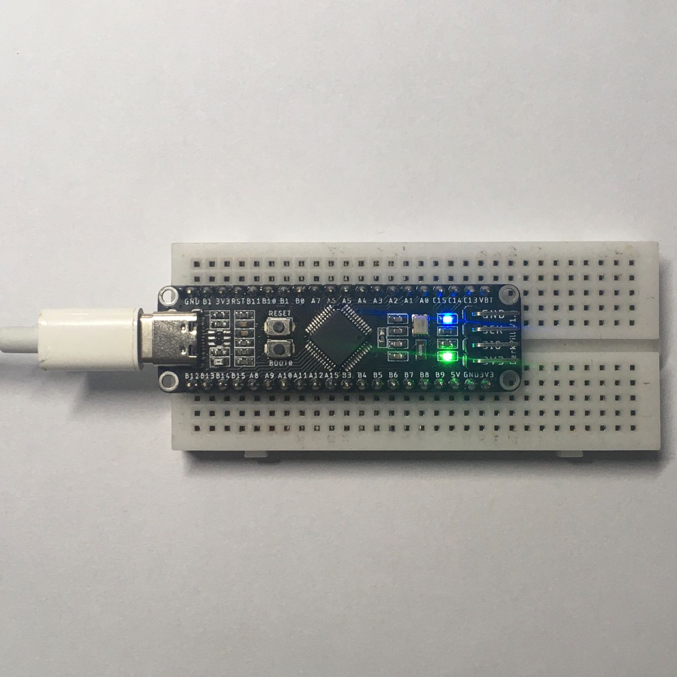
A STM32 development board Improved from BluePill
Pin B1 is repeated twice (BOOT1 and PB1), this problem has been modified to B2 in the shared PCB file :)
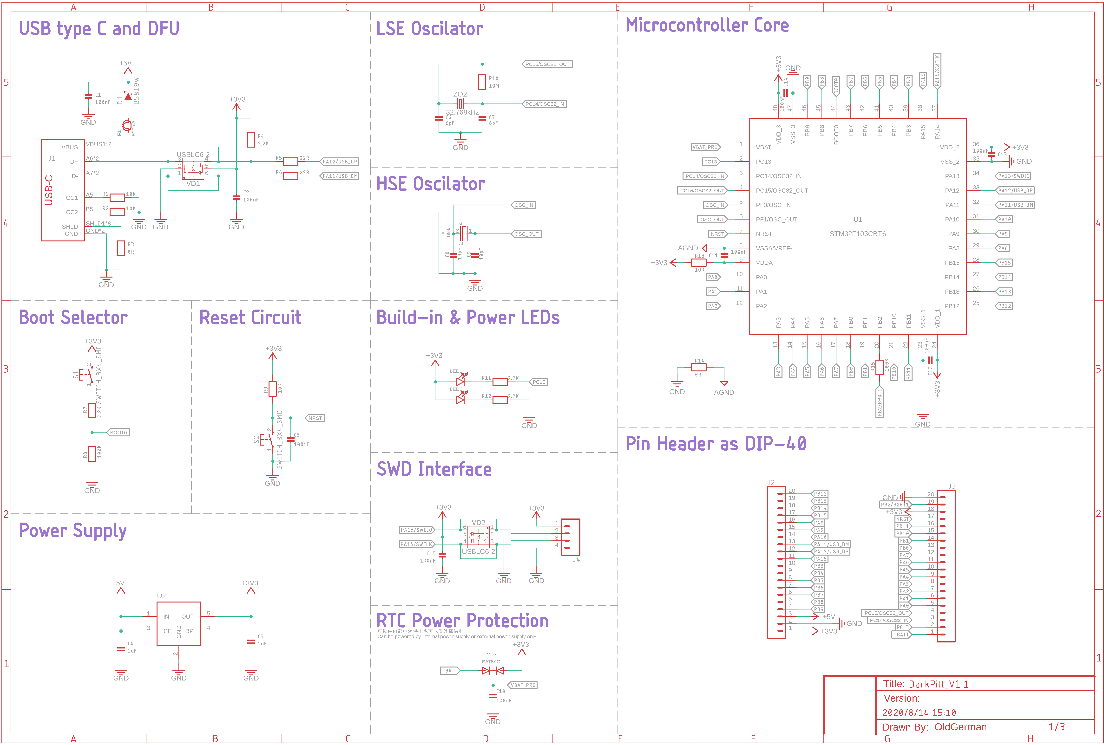
- Support LQFP48 packages such as STM32F030, F072,F103,F303,G474...
- Pin to pin with BluePill development kits(Except B2).
- Double-sided PCB layout, the board thickness is 1.0mm, size 59.7mm x17.8mm, both pads and vias have teardrops...
- Center symmetrical design.
- Discrete components are packaged in 0603, which is easy to solder by hand.
- There are four M2 holes around the PCB that are easy to fix.
- USB C Connector supports positive and negative insertion.
- Use the USBLC6-2 ic to ESD protection, Don't need to solder it will not affect the serial port work.
Please see bom/ibom.html or following:
| Num | Qty | Value | Device | Package | Parts |
|---|---|---|---|---|---|
| 1 | 1 | STM32F103CBT6 | STM32F303CBT6 | TQFP48 | U1 |
| 2 | 1 | ME6211C33M5G-N | 3.3V 500mA LDO | SOT23-5 | U2 |
| 3 | 2 | USBLC6-2 | USBLC6-2-SOT23-6 | SOT23-6 | VD1, VD2 |
| 4 | 1 | BAT54C | BAT54C | SOT23-R | VD3 |
| 5 | 1 | B5819W | B5819W-SOD323 | SOD-323 | D1 |
| 6 | 1 | 500mA | FUSE | 0603 | F1 |
| 7 | 2 | LED | LED_0603_MICRO | 0603_LED | LED1, LED2 LED |
| 8 | 2 | 0R | RESISTOR0603 | 0603 | R3, R14 |
| 9 | 1 | 10R | RESISTOR0603 | 0603 | R13 Resistors |
| 10 | 2 | 22R | RESISTOR0603 | 0603 | R5, R6 |
| 11 | 4 | 2.2K | RESISTOR0603 | 0603 | R4, R7, R11, R12 |
| 12 | 3 | 10K | RESISTOR0603 | 0603 | R1, R2, R9 |
| 13 | 2 | 100K | RESISTOR0603 | 0603 | R8, R15 |
| 14 | 1 | 10M | RESISTOR0603 | 0603 | R10 |
| 15 | 2 | 6.8pF | CAP_CERAMIC0603 | 0603 | C6, C7 |
| 16 | 2 | 10pF | CAP_CERAMIC0603 | 0603 | C8, C9 |
| 17 | 9 | 100nF | CAP_CERAMIC0603 | 0603 | C1, C2, C3, C10, C11, C12, C13, C14, C15 |
| 18 | 2 | 1uF | CAP_CERAMIC0603 | 0603 | C4, C5 |
| 19 | 1 | 8/12/16MHz | 3225_CRYSTALL | 3.2X2.5_KX-7 | ZO1 |
| 20 | 1 | 32.768kHz | KX-327-NHF CRYSTALL | 3.2X1.5 | ZO2 |
| 21 | 2 | SWITCH_3X4_SMD | SWITCH_3X4_SMD | SWITCH_3X4_SMD | S1, S2 |
| 22 | 1 | USB_C2-LAYER | USB-C-16P | J1 USB Type C 16Pin Connector | |
| 23 | 2 | CONN_20 | 1X20 | J2, J3 | |
| 24 | 1 | CONN_04PTH | 1X4 | J4 |
If the U1 chip is STM32F103 and Programming STM32duino-bootloader with Arduino_STM32 for DFU upgrade, the frequency of 3225 crystal oscillator must be 8, 12 or 16MHz, because these frequencies can be divisible by the USB clock of 48Mhz. In order to save a lot of trouble, it is best to use an 8MHz crystal oscillator, but the 3225 package may not be easy to reach, such as KDS DSX321G.
If you use 12 or 16MHz, you need to build an arm tool chain and use make to recompile STM32duino-bootloader. Fortunately, I have compiled 12MHz and 16MHz STM32duino-bootloader, you can use it directly. However, it is not enough to just burn it, you also need to change the PLL multiplier value in boards_setup.cpp in the ArduinoSTM32 folder. See here for details.
若U1芯片为STM32F103,并且烧录STM32duino-bootloader配合Arduino_STM32以进行DFU升级,那么3225晶振的频率必须为8、12或16MHz,因为这些频率可以被USB时钟48Mhz整除。为了省去很多麻烦,最好使用8MHz的晶振,但是3225封装的可能不太好买到,例如KDS DSX321G。
若使用12或16MHz,需要搭建arm工具链,使用make重新编译STM32duino-bootloader,幸运的是,我已经编译好了12MHz和16MHz的STM32duino-bootloader,你可以直接使用。但是,仅仅烧录它是不够的,还需要改动ArduinoSTM32文件夹里的boards_setup.cpp中的PLL倍频的值,步骤详见此处。
| Connection | 1.Arduino IDE | 2.FlyMCU |
|---|---|---|
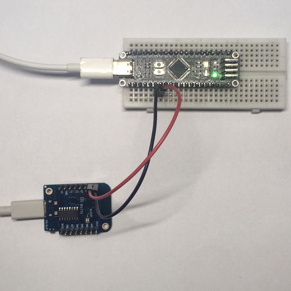 |
.png) |
.png) |
| Connection | 1.Arduino IDE | 2.STM32 ST-LINK Utility |
|---|---|---|
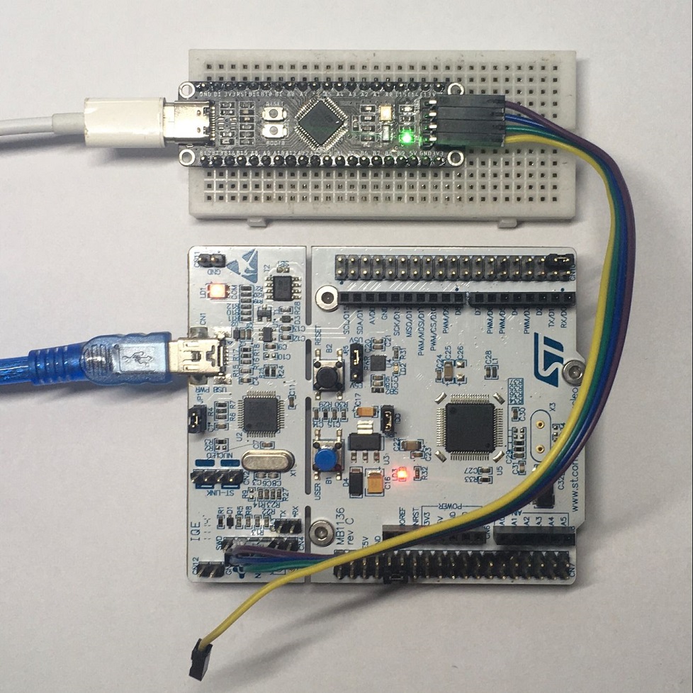 |
.png) |
.png) |
| Connection | 1.Arduino IDE(with STM32duino-bootloader) | 2.DfuSeDemo |
|---|---|---|
 |
.png) |
stm32-dfu-bootloaderNot yet successful. |
Both using Serial or ST-LINK programming with STM32duino-bootloader will disable the STM32duino-bootloader DFU function, and the symptoms are: the LED of PC13 cannot flash after Reset is pressed.:flushed:
在STM32duino-bootloader下使用串行或ST-LINK编程都将禁用STM32duino-bootloader DFU功能,其症状为:按下Reset后PC13的LED无法闪烁.:flushed:
| U1 | DFU | DfuSeDemo |
|---|---|---|
.png) |
.png) |
.png) |
.png)
.png)

