Make your own base station to communicate with satellites!
We have a discord server for collaboration, questions and to just show off!
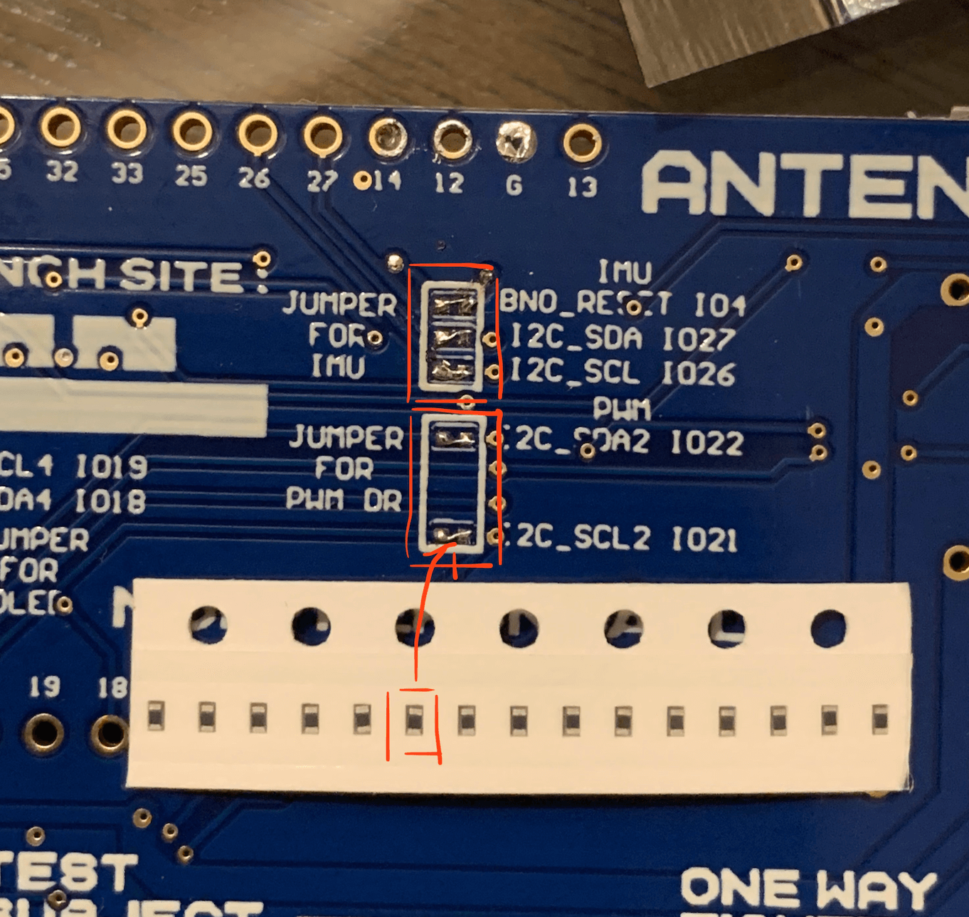
- On the antenny MK7 there are two required jumpers, labeled
JUMPER FOR PWN DRon the back of the board. This will bridge the GPIO to the on board PWM Driver.
-
The antenny MK7 provides jumpers to breakout pins 4, 26, 27, VCC and GND to the header labeled
P11for the IMU. To use this header, you must solder the jumpers labeledJUMPER FOR IMU, otherwise, just used the ESP32 GPIO headers. -
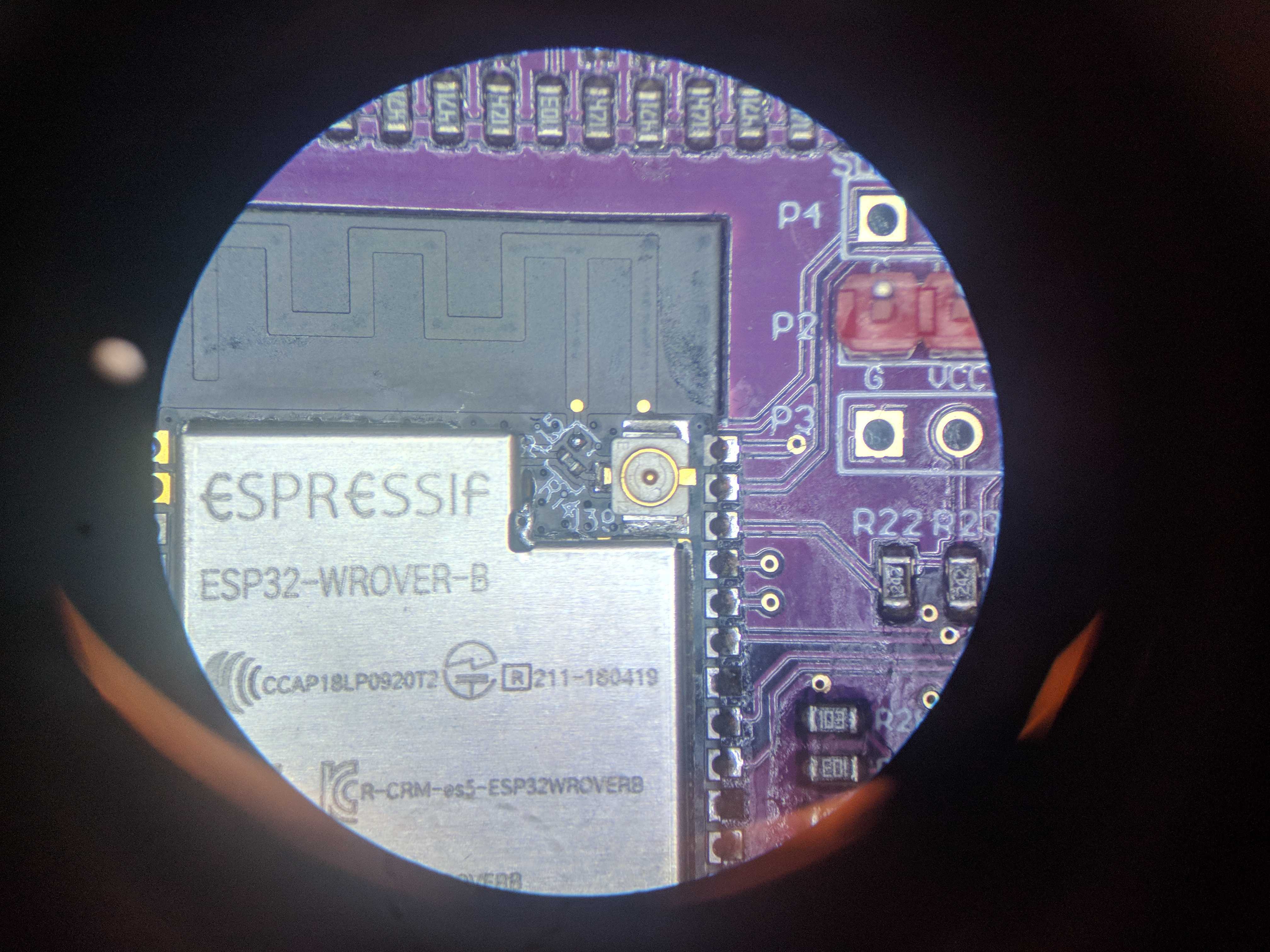
To use wifi, either provide a antenna to the ESP32s on board jack, or solder the jumper next to the antenna connector labeled
R15on the ESP32. See below picture.
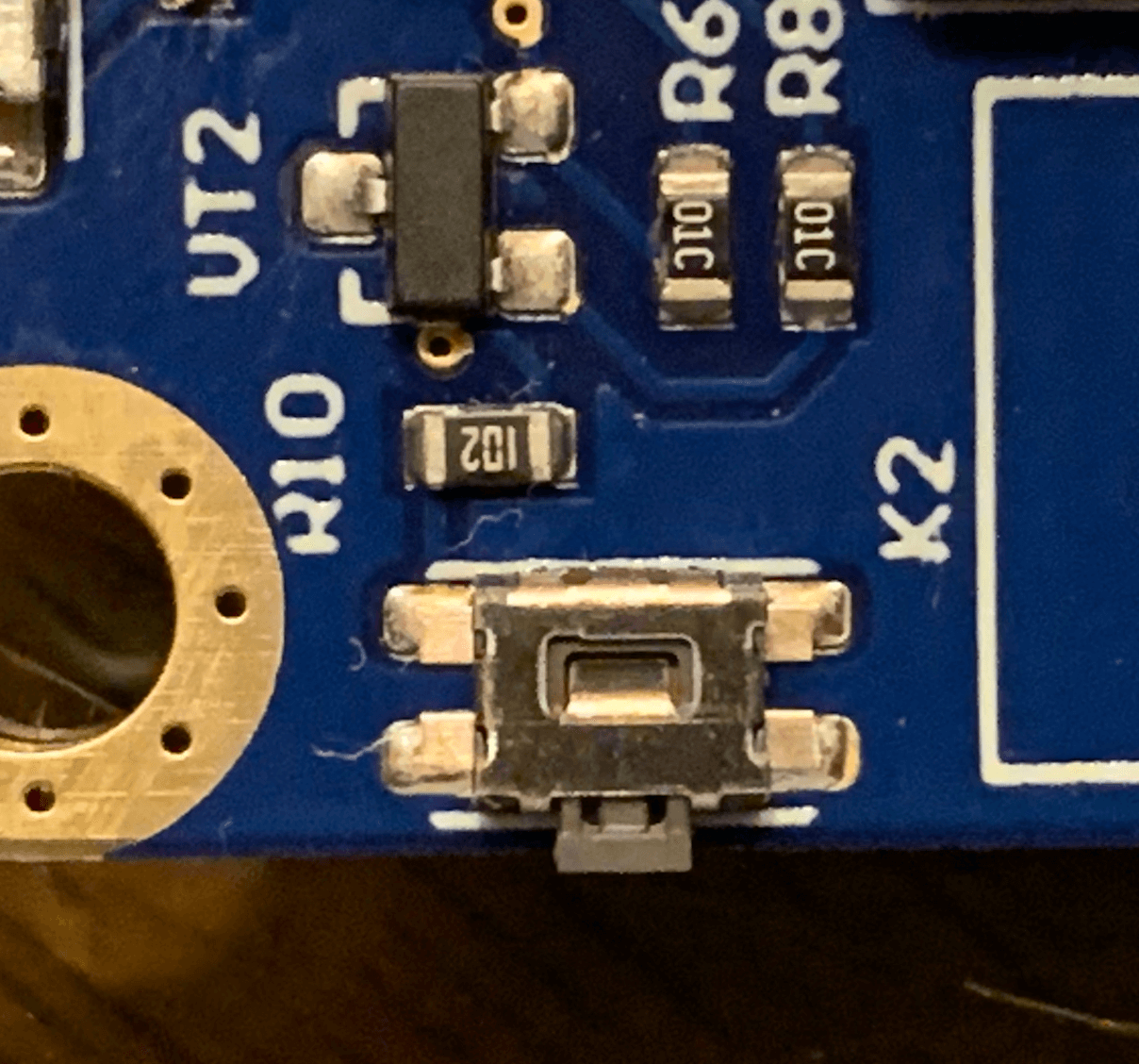
- Important: When you start to program the Antenny board with esptool, please hold the K2 Tact Button until the program detect the download mode.
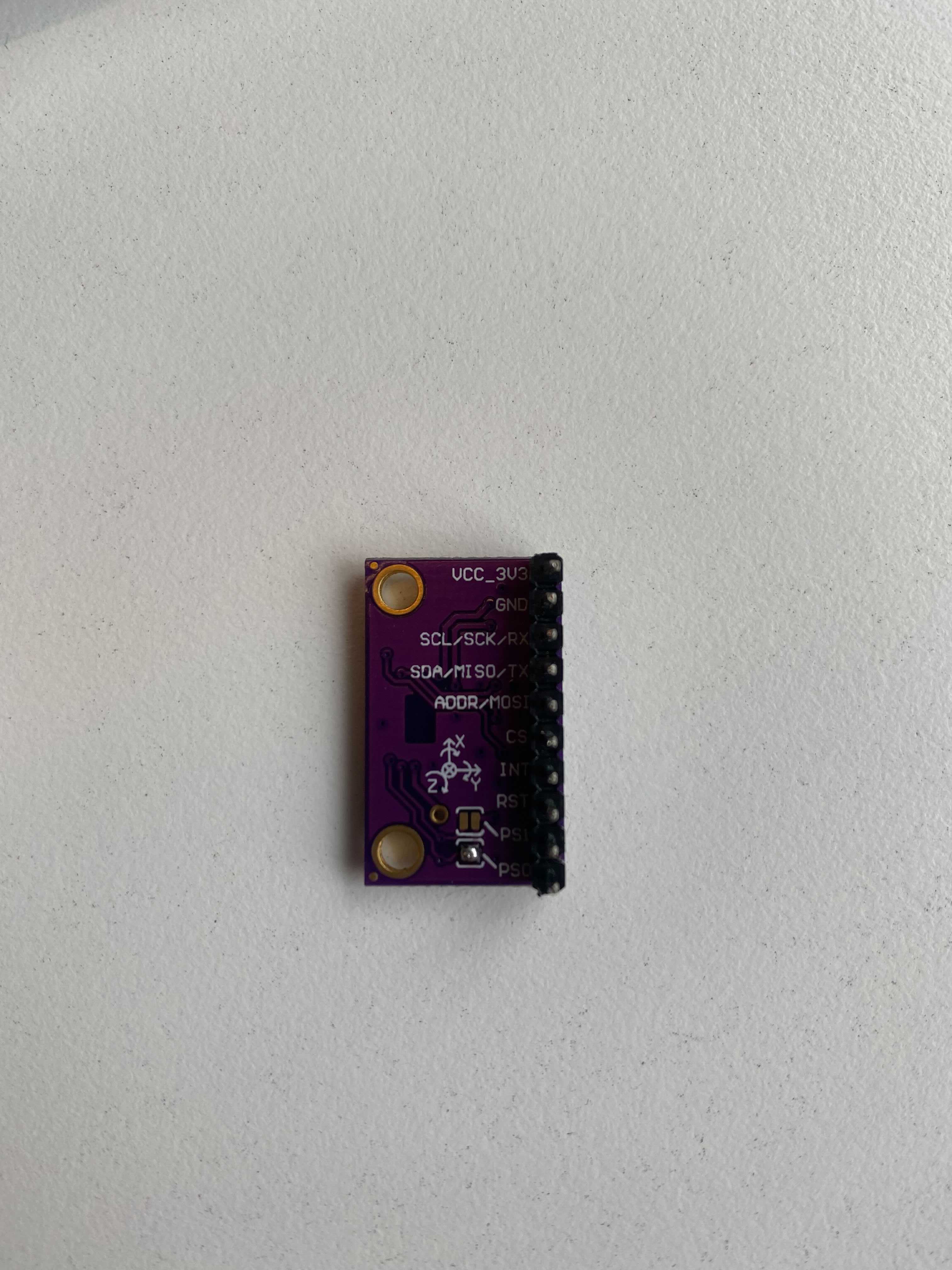
There is one optional IMU jumper. This is used to select the IMU mode. More info can be found in the BNO080 datasheet If you do not want to use the jumper, you can use pins to select the correct mode. This can also be useful for switching between modes in software.
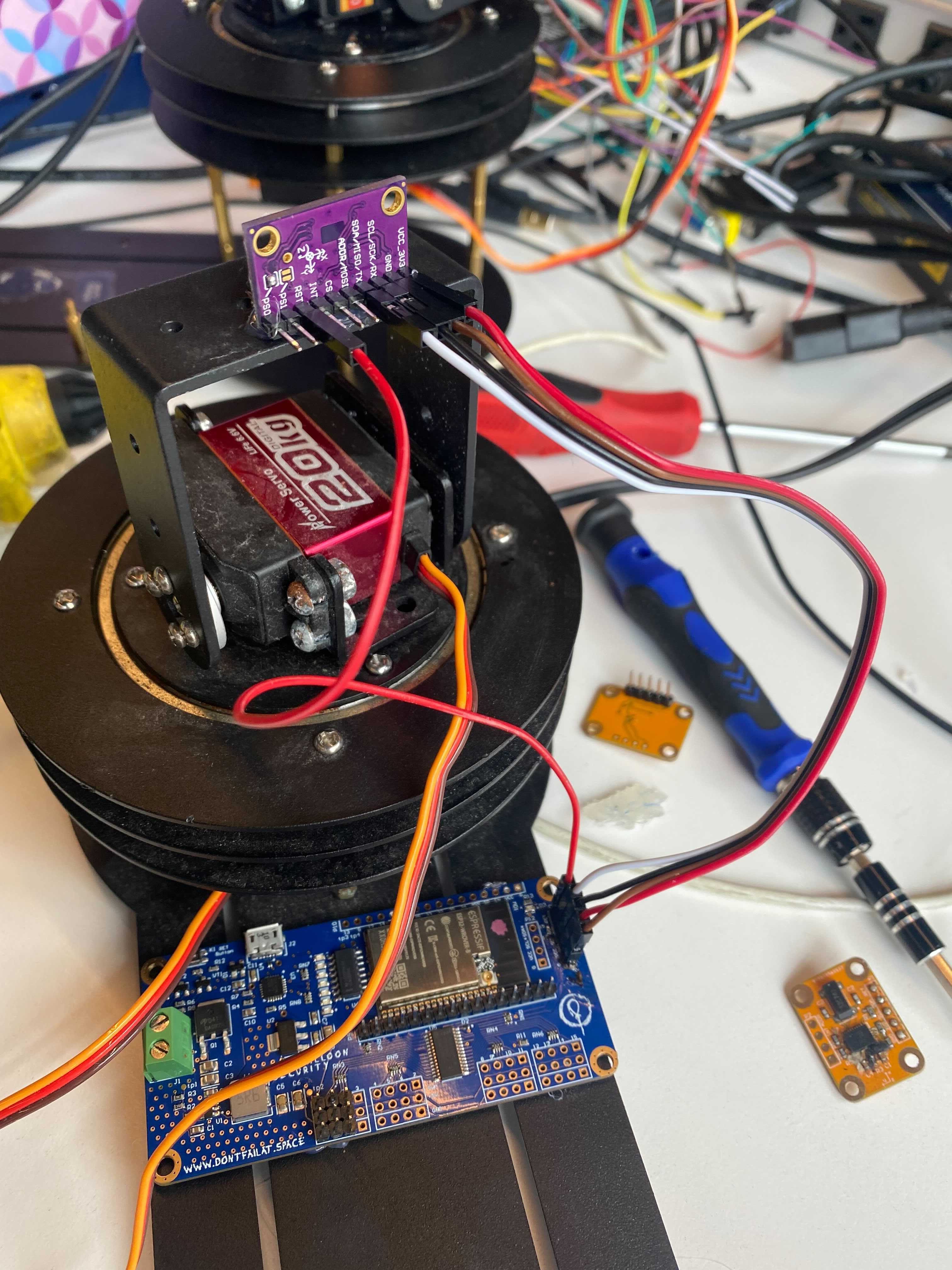
The mode we use is the Robotic Vacuum Cleaner (RVC) mode. To enable this you can provide power to the PS0 pin using the jumper as shown below.
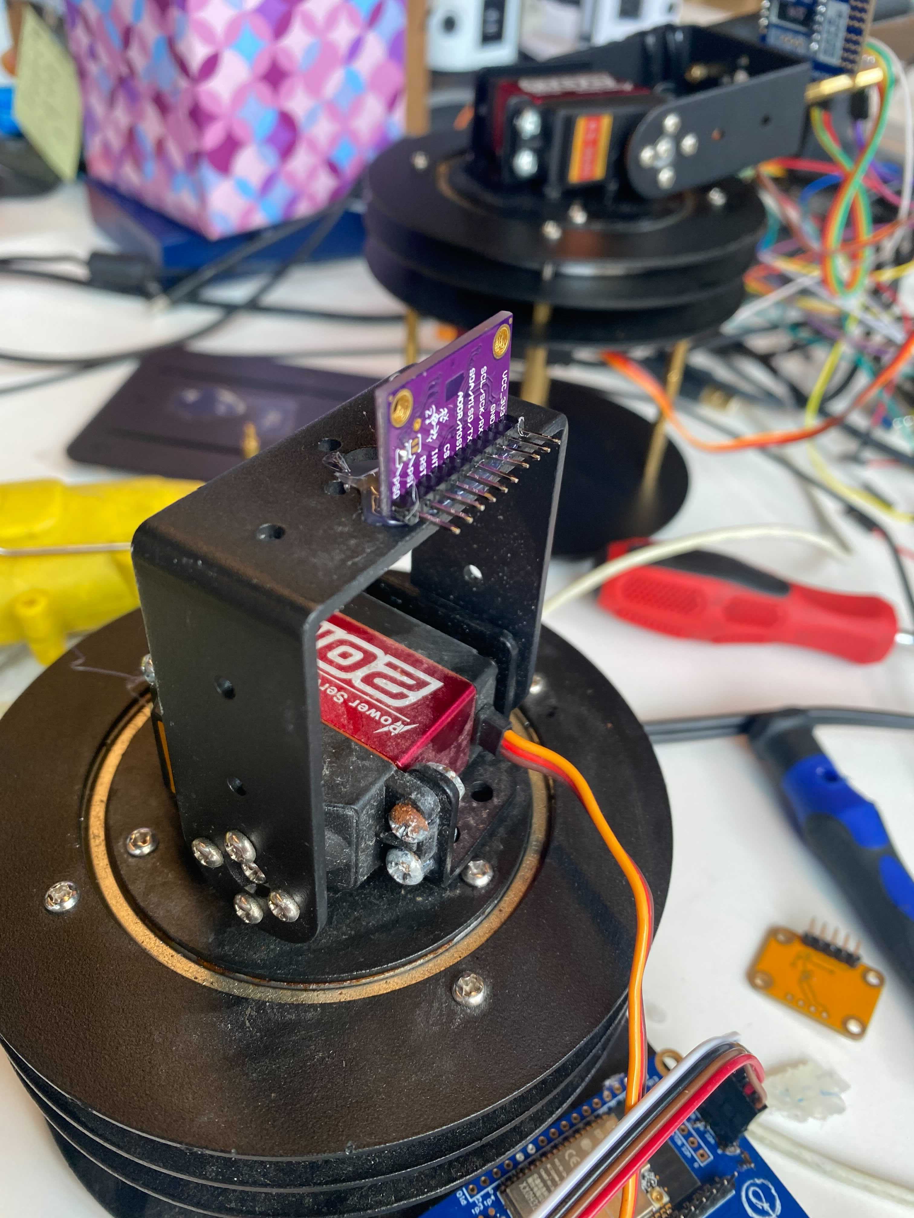
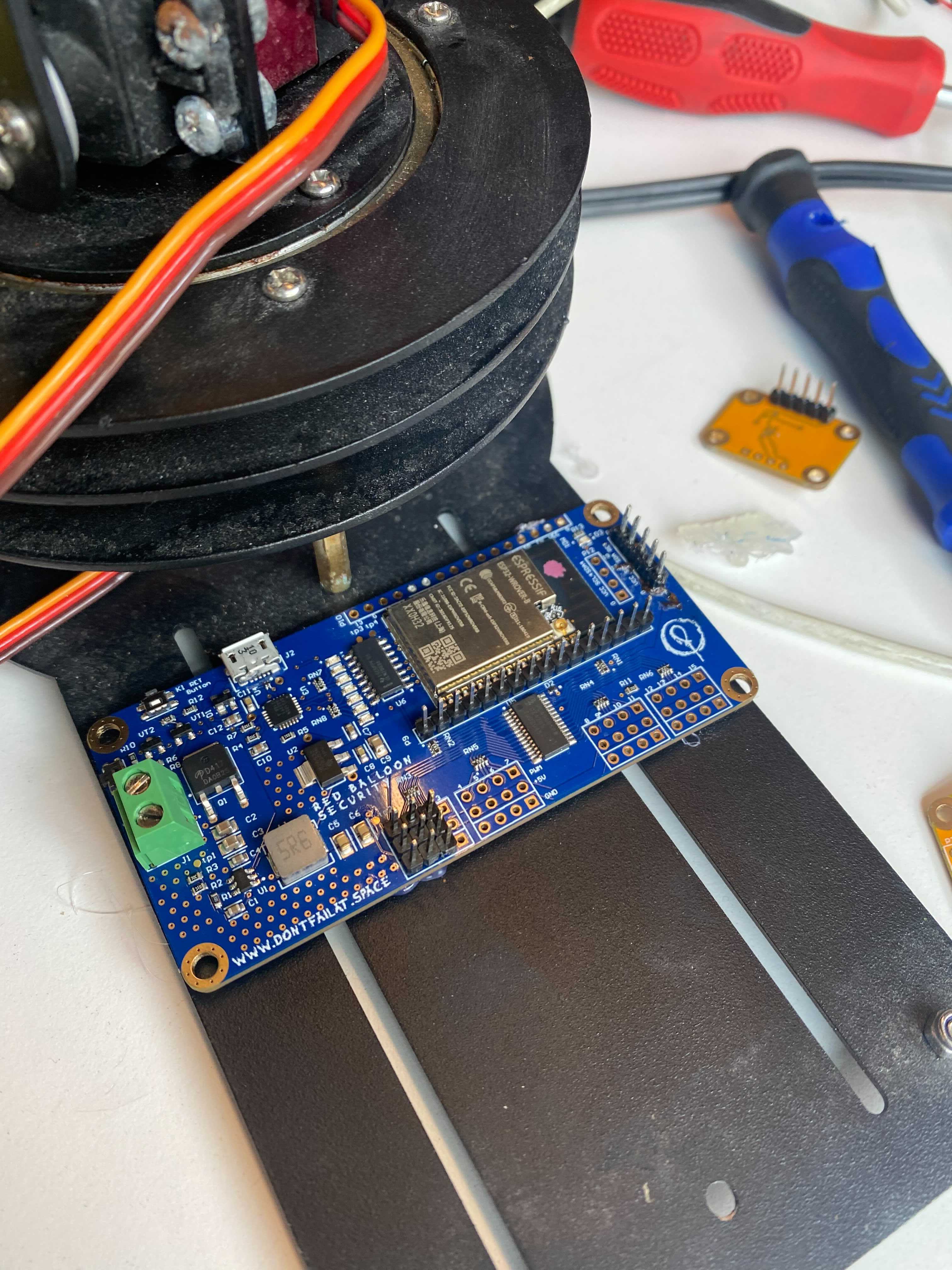
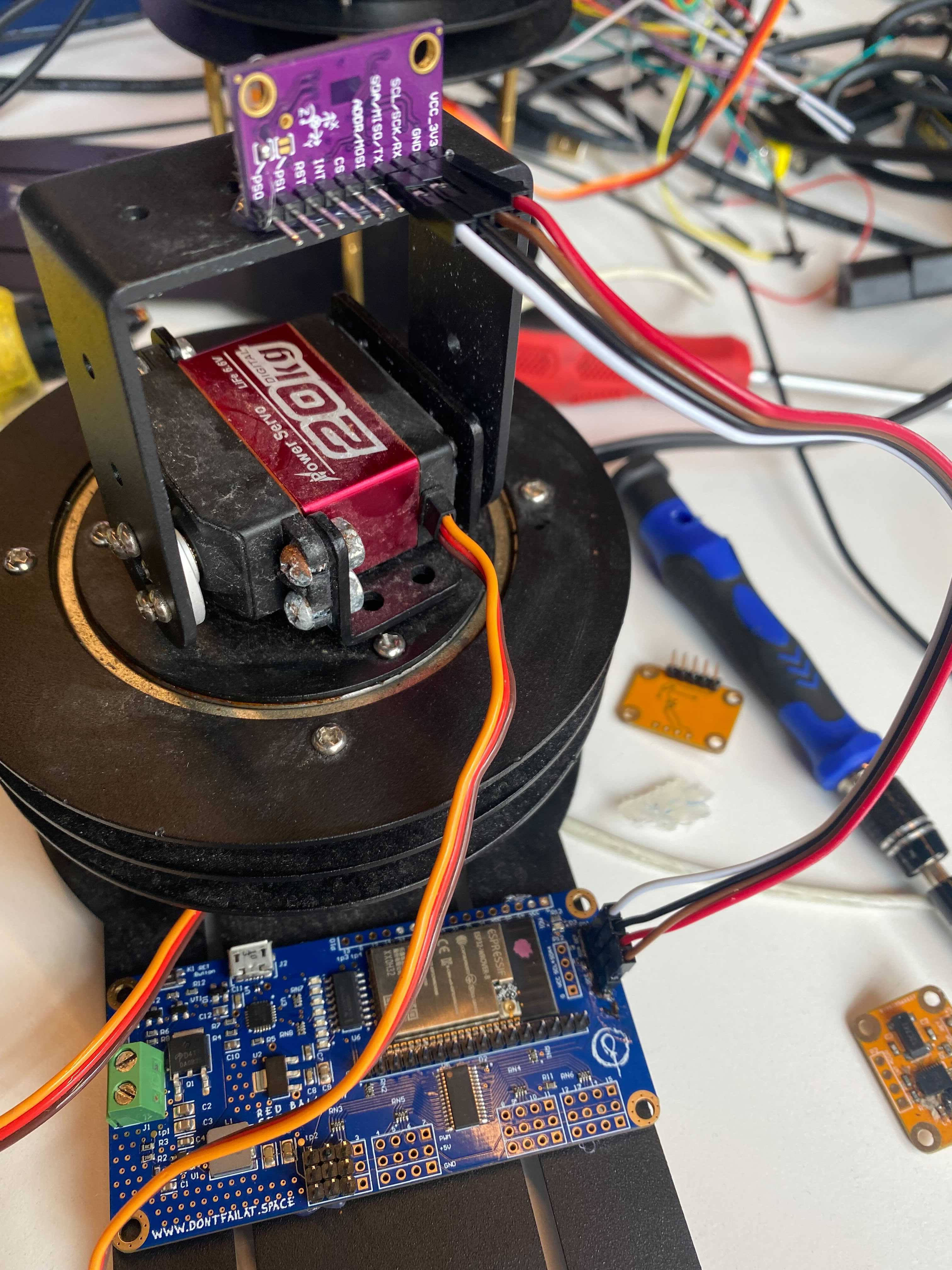
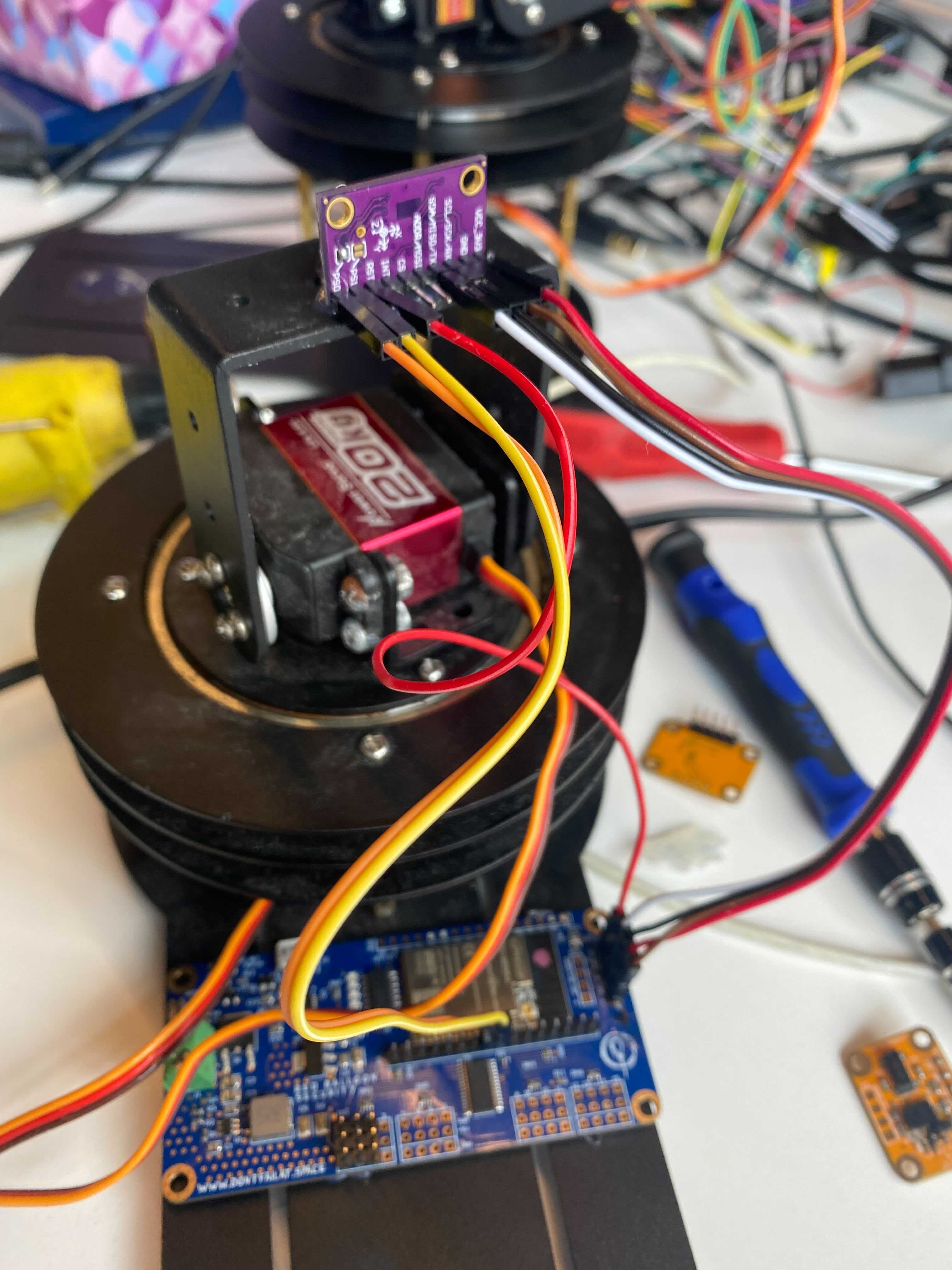
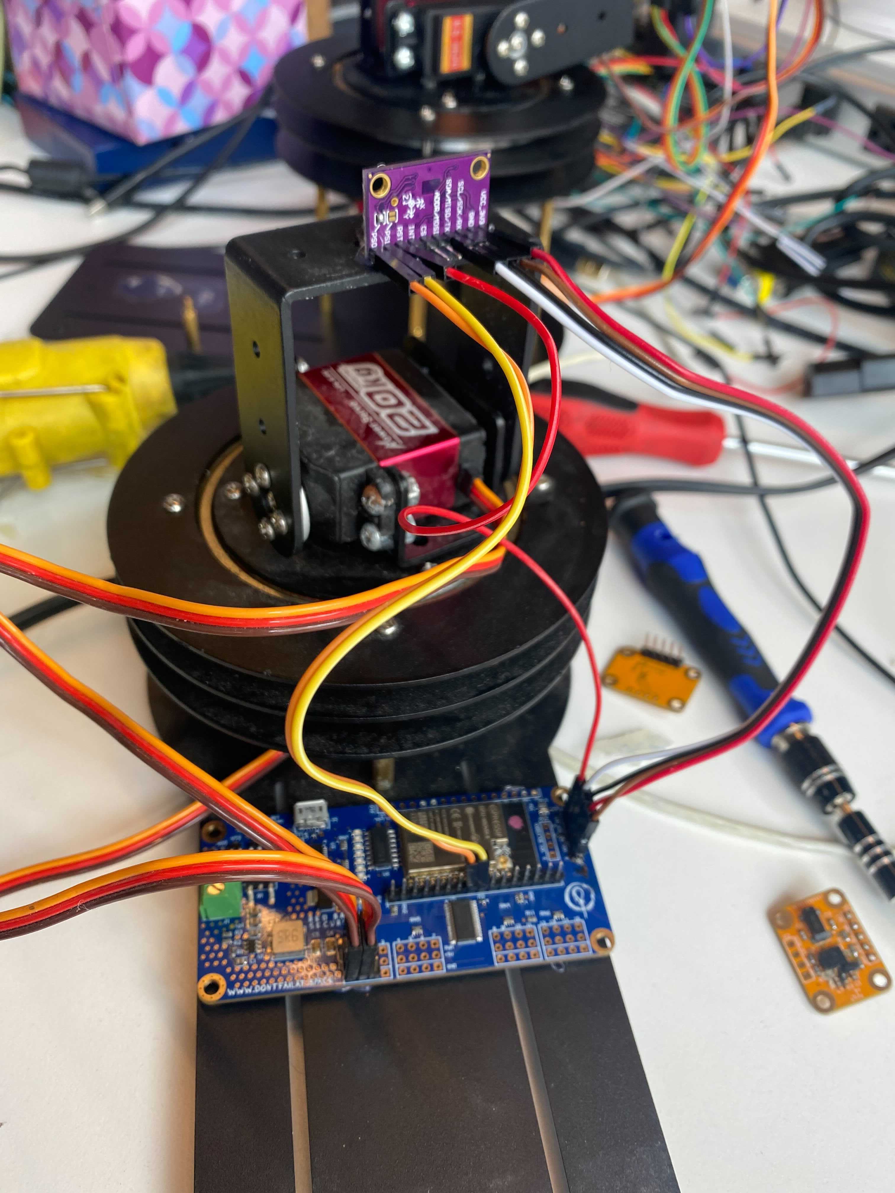
This will go over how to setup the servo gimbal, IMU and antenny board. I used hot glue to secure the hardware, but more creative approaches are welcome.
####Step 1: Position the IMU Position the IMU on the gimbal arm. The position show below will give the correct orientation. If you want a different IMU position, you can correct the elevation angle in software.
Next we secure the Antenny to the platform. It is advised to isolate the pins from any metal contact.
NOTE: From this point on, the pins you use are configurable from the antenny_config, as described in the software
guide below. To verify your pins or reconfigure as you wish, it is suggested you edit the config through the
antenny_manual_setup command described in the software guide.
The IMU communication lines are labeled on both the IMU PCB and the Antenny PCB, just match them up, as shown.
Same as step 3, it is labeled.
If you did not solder the IMU jumper, you must pick two pins to use to control PS0 and PS1. If using this approach,
its suggested you setup these pins using the antenny_manual_setup.
Next we wire the servos to the PWM controller. By default the elevation(top) servo goes to pwm index 0 and azimuth (bottom) goes to index 1, but this is, again, configurable.
-
Download and install the USB driver for the CP210 USB to UART chip here
-
Download esptool from here
-
Put the ESP into download mode (see above) and erase your ESP32
Example:
python3 -m esptool --port /dev/tty.SLAB_USBtoUART erase_flash -
Download the micropython firmware from here
-
Put the ESP into download mode (see above) and re-flash the Micropython firmware
Example:
python3 -m esptool --chip esp32 --port /dev/tty.SLAB_USBtoUART --baud 115200 write_flash -z 0x1000 ~/Downloads/esp32spiram-20210623-v1.16.bin
-
We use MPFShell to upload the python files to the board. First you must install this on your host computer with
python3 -m pip install mpfshell. -
To begin install, first push the reset button on the antenny board, labeled
RET Button. -
Next, from the root directory of this repository, run the
make nyansatmake directive with theSERIALargument pointing to your antenny block device.Example:
make nyansat SERIAL=/dev/tty.SLAB_USBtoUART -
The Installer will give you a series of prompts.
-
Do you want to do an installation of all components and libraries?(Y/n)- If this is your first install, or you would like to do a fresh install of all code select
Y, otherwise, if you would only like to install specific components selectN.
- If this is your first install, or you would like to do a fresh install of all code select
-
If you selected
Yfor the previous prompt you will see:-
Are you sure you want to erase all files on the device? (y/N)- This is just a confirmation, as a full install will take a bit of time.
-
-
If you selected
Nyou will see:-
Name a component you wish to install: -
Do you wish to install more? (y/N)- Use this to repeat the above step.
-
Do you want to keep the configs on the device? (Y/n).- If you would like to restart your antenny configs from the repository state, select
N, to keep your configs on board selectY.
- If you would like to restart your antenny configs from the repository state, select
-
Do you want to re-install the libraries (y/N)- Select yes to reinstall the libraries found here
-
-
-
You should see the installer upload the code to the antenny.
-
You will see the installer report
Falseupon completion, pressEnterto continue. -
The installer will prompt you for your WiFi info. If the above steps were taken to enable WiFi, enter your info, otherwise leave blank.
Your installation is complete!
-
Using a terminal utility of your choice, enter the devices python interpreter.
-
Examples:
screen <block device> 115200or
minicom -D <block device> -b 115200 -
In the case of windows, Putty is suggested.
-
-
Upon entering the interpreter you should be met with the python prompt
>>>. If you are not try the reset button on the side of the board or revisit theInstalling Micropythonsection of this README. -
To view any potential import errors, press the reset button on the board as described in the installation section.
- In micropython, the first script run on startup will always be
boot.pyfollowed bymain.py. Themain.pyscript will import all relevant antenny code and provide access toapi, an instance of AntennyAPI.
- In micropython, the first script run on startup will always be
Once your hardware is properly setup and you have installed the antenny station code, you can begin working with the
device. To interface with the device from the python interpreter, we will use member methods of the api class.
High level methods start with antenny_ are used to setup your antenny assembly, calibrate and save calibration data.
-
api.antenny_init_components()- Initializes the components described by the current config. For more info on device configuration, please see the "Configuring Antenny" section.
-
api.antenny_calibrate()- Calibrates the antenny platform.
- NOTE: This will start the automatic calibration routine. Currently, IMU calibration only supported by the BNO055 IMU. BNO080 support expected soon.
-
api.antenny_save(name: Optional)- Saves the current configuration of each component as default. With an optional name. Makes the state of the configuration and calibration persistent.
-
api.antenny_manual_setup()- This will walk you through manual configuration of the antenny board and its components. Useful if it is your first time setting up, or for easier access to some of the more useful config entries.
Platform methods start with platform_ and are used to operate the platform, a term used in this project to describe
the pwm driver, the motors it is driving, the IMU and the antenny board as a single assembly.
-
api.platform_orient()- Orients the platform to its current position. Should be run after repositioning the gimbal platform. This finds the 90 degree dead zone of the azimuth servo.
-
api.platform_start()- Enables movement of the platform. Commands can be issued to point at specific coordinates.
-
api.platform_stop()- Disables movement of the platform. Commands can be issues to manually move the servods or re-orient the platform.
-
api.platform_set_azimuth(az: int)- Sets the azimuth coordinate of the platform while movement is enabled.
-
api.platform_set_elevation(el: int)- Sets the azimuth coordinate of the platform while movement is enabled.
-
api.platform_set_coordinates(az: int, el: int)- Sets both coordinates of the platform while movement is enabled.
Each individual servo can be operated manually through these methods. Without access to the IMU the servos will not know they're orientation.
-
api.elevation_servo_set_position -
api.azimuth_servo_set_position- Sets the position of the elevation servo. The current specs for the servos provided with the antenny put the position argument in range(0, 4096), however only a subset of that range will actually move the servo.
-
api.elevation_servo_set_min_max(min: int, max: int) -
api.azimuth_servo_set_min_max(min: int, max: int)- Sets the minimum and maximum
positionarguments that allow the servo to move, part of the higher level calibration step.
- Sets the minimum and maximum
IMU data can be accessed directly from the API as well.
-
api.imu_get_azimuth()- Returns the azimuth in degrees as reported by the IMU
-
api.imu_get_elevation()- Returns the elevation in degrees as reported by the IMU
-
api.imu_get_euler()- Returns the euler angles in order of yaw, roll, pitch.
The IMU can also be manually calibrated
-
api.imu_calibrate()- Begins the calibration routine. For best results, follow the printed instructions from the console.
There are plenty of other methods, most used for debugging, available to the user, as well as direct access to underlying components. For more information, reading through the antenny code is advised.
NOTE: These configs have wrappers to properly alter the config members before saving in the API. In general only the
High Level api.antenny_save(name: Optional) should be used by users.
Your hardware is described by a series of configs that can be updated through your installer or on the antenny board itself. This section will go over on baord config modification. To use the installer re-visit the above guide.
The api uses the
Config class to
manage configs and are exposed by the AntennyAPI. There are currently three configs used by the antenny system, but
any components that require information to be stored across boots should use its own config.
-
api.antenny_config- The antenny_config describes the base station integration with pin connections as well as high-level attributes like current longitude and latitude.
- Help information for each antenny_config member can be retrieved via
api.antenny_config_help()
-
api.imu_config- The imu_config describes calibration data of the IMU. Currently only available for the BNO055, for more details on this you can view the BNO055 and BNO08x data sheets.
-
api.servo_config- The servo_config describes the limits of the servo motors.
-
Config.set(<member>, <value>): Sets a config to a new value. -
Config.get(<member>): Gets the current value of a config member. -
Config.save(name: Optional): Saves the current config to the device, with a new name option for multiple configs. -
Config.load(name: Optional): Loads the currently saved values, if name is specified, loads from a previously saved config, if it is not, reloads the last save of the current config. -
Config.save_as_default_config(): The current config will be loaded on reboot. -
Config.load_default_config(): Load the config that was present on reboot.
Under Development...
Cooperation between the antenny board and another system is possible through the antenny client as well as the UDP Sender. Use of the client is not suggested while developing on or debugging the system, but could be useful for more interesting applications such as beacon tracking.
The command_invoker is a 1:1 library to the antenny api class found at nyansat/host/shell/command_invoker.py. The
command_invoker calls out to the board through MPFShell to exec API commands. Feedback and error handling does not
work very well so work should be offloaded to the board when possible.
The antenny_client, found at nyansat/host/shell/antenny_client.py should use the command invoker to implement
higher level functions in conjunction with more computationally expensive libraries.
Current depricated.
The antenny client can then be integrated into the MPFShell environment through nyansat/host/shell/__main__.py.
Commands of the format do_<cmd>() will be used as shell commands. See the file for examples. This shell can then be
run through the command make nyanshell.
- The BNO08x calibration never finishes :(
- The BNO08x euler angles are incorrect (maybe calibration, maybe I'm bad at math, probably both.)
##Requirements
- Python >= 3.6
NyanShell:
- MPFShell
- TUI-DOM
