A simple breakout board for PEC11 rotary encoders (as sold by Adafruit).
Designed to be paired with a 4 pin JST header
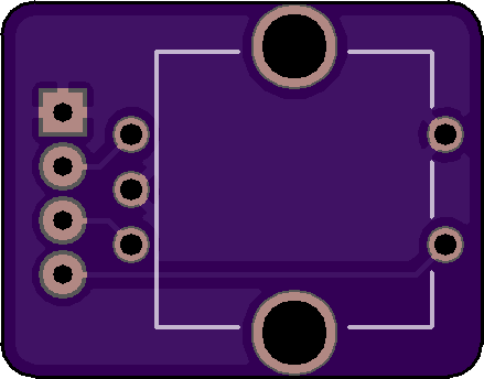
Pinouts in the above image from top to bottom are:
- Ground
- A (quadrature trigger)
- B (quadrature direction)
- Z (button press)
If you're new to rotary encoders, their use can be non-obvious. The typical approach I take is to:
- Set up pullup resistors on both pins A and B.
- Set up an edge triggered GPIO monitor on pin A, looking at rising edges only.
- When you see a rising edge on A, immediately read the value of B. If it's high, you just rotated clockwise. If it's low, you just rotated counter-clockwise.
Available at OSH Park
MIT