Welcome to The Galaxino.
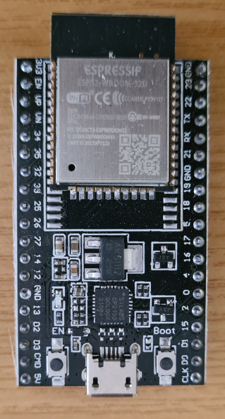
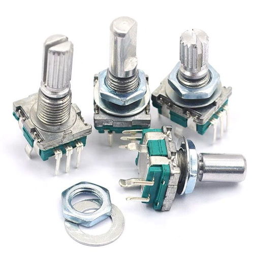
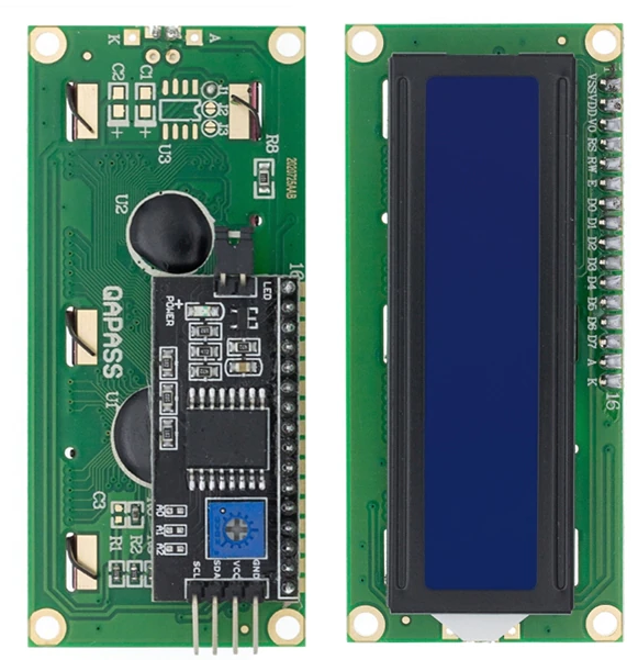
The Galaxino is an interface designed to replace the audio recorder to be combined with the Galaksija computer. It allows you to play software recorded in GTP and WAV format (there is a large library of software in both formats) as well as to record software in GTP format. The data is stored on a SD Card formatted in FAT mode. The data is visualized by means of a 16 x 2 LCD display, while a rotary encoder or, alternatively, four buttons can be used for input. The heart of the system is an ESP32 DevKit module. The 5V power supply can be supplied both from the USB socket on the ESP32 module and from the USB C socket on the circuit; the latter USB C socket is only for power supply.
Most of the code has been written and tested to a good extent, but there may still be some bugs. Please report any bugs as issues through the repository.
Instructions on how to navigate the UI and detail on the Galaxino functionality can be found on this page: The Galaxino UI.
- schematics and designs for reference implementations are available in the Schematics folder.
The BOM for The Galaxino is:
-
resistors:
- 1 x 100 Ohm
- 2 x 330 Ohm
- 1 x 1 KOhm
- 1 x 1.5 KOhm
- 2 x 2 KOhm (2.2 KOhm)
- 1 x 3.3 KOhm
- 6 x 10 KOhm
- 1 x 100 KOhm
-
capacitors:
- 5 x 100 nF polyester or ceramic 25V
- 2 x 10 uF electrolytic 25V
- 1 x 220 pF ceramic 25V
-
ics:
- LM358
- DS1307 (optional RTC)
-
transistors:
- 1 x 2N3904
-
diodes:
- 1 x LED RED
-
various:
- 1 x XTal 32KHz (optional RTC)
- 1 x CR2032 Battery holder (optional RTC)
- 1 x CR2032 Battery (optional RTC)
- 1 x DIN 8 pole connector
- 1 x USB C (power) connector
- 1 x SD Card socket
- 1 x Rotary Encodoer OR
- 4 x Push button
- 1 x LCD1602 Module
- 1 x ESP32 Devkit
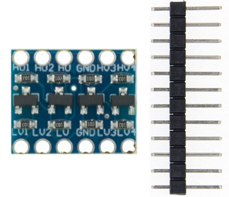
- 1 x Logic Level Converter (optional for Commodore future expansion)
- 2 x pin connector female 19 pin (1 x 40 pin to be cutted)
- 1 x pin connector male 6 pin
The components marked as (optional) must be installed only if you want to have the real time clock working. This is just to have the right time when files are recorded.
- ESP32 Devkit equivalent: https://it.aliexpress.com/item/1005001621012182.html
- Rotary encoder EC11W: https://it.aliexpress.com/item/1005004494451358.html
- LCD screen: LCD1602: https://it.aliexpress.com/item/32413056677.html
- Logic Level Converter: https://www.aliexpress.com/item/32458109285.html
-
SD Card socket: https://it.aliexpress.com/item/1005002327556213.html
-
DIN 8 pole connector: https://it.aliexpress.com/item/32981543684.html
-
USB C (power) connector: https://it.aliexpress.com/item/1005003101061485.html (Type 06)
-
Battery socket (optional): https://it.aliexpress.com/item/4000311603296.html
-
32KHz xtal (optional): https://it.aliexpress.com/item/4000124720113.html
The PCB (printed circuit board)
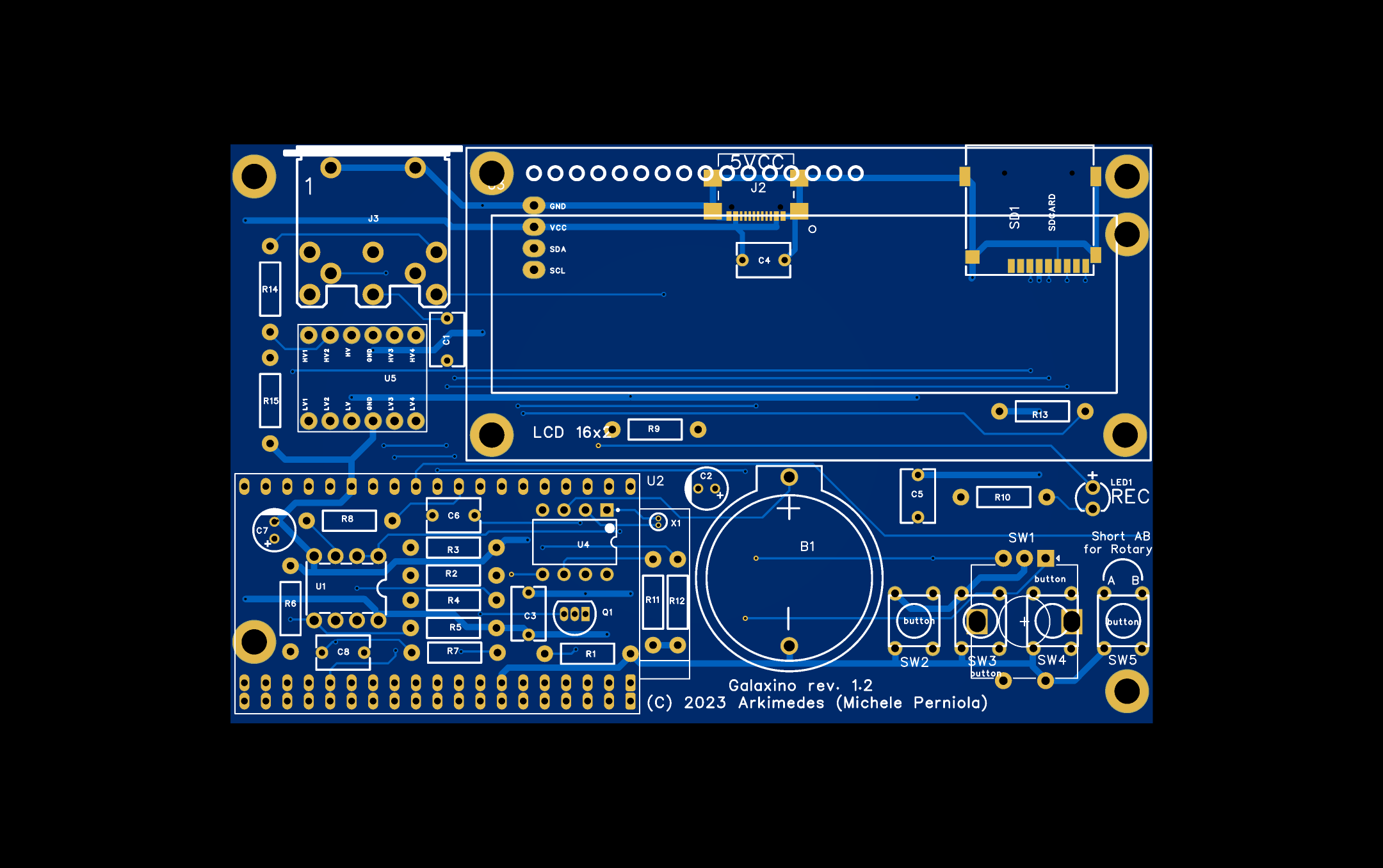
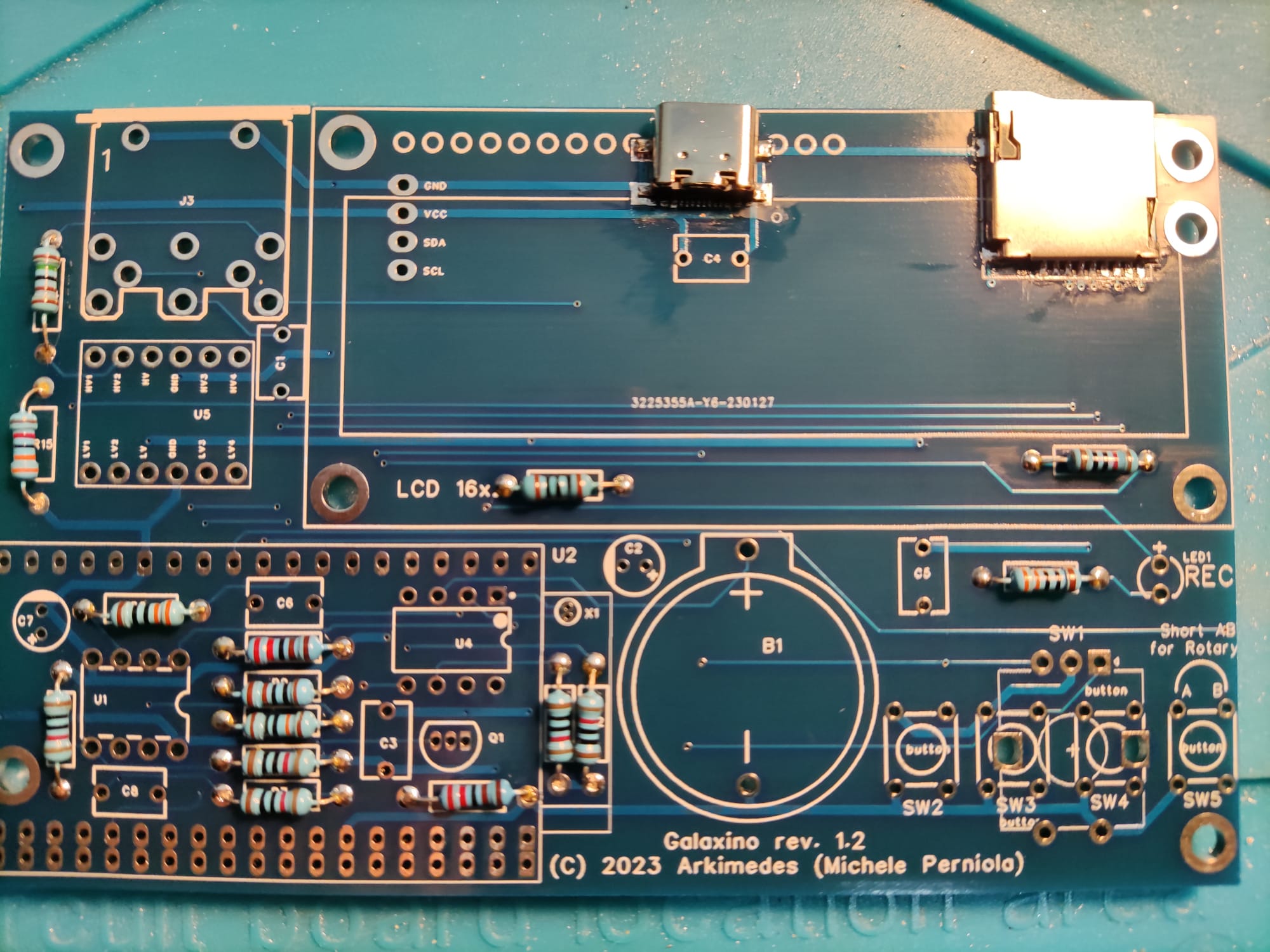
- 1 Assembly of smd connectors and resistors
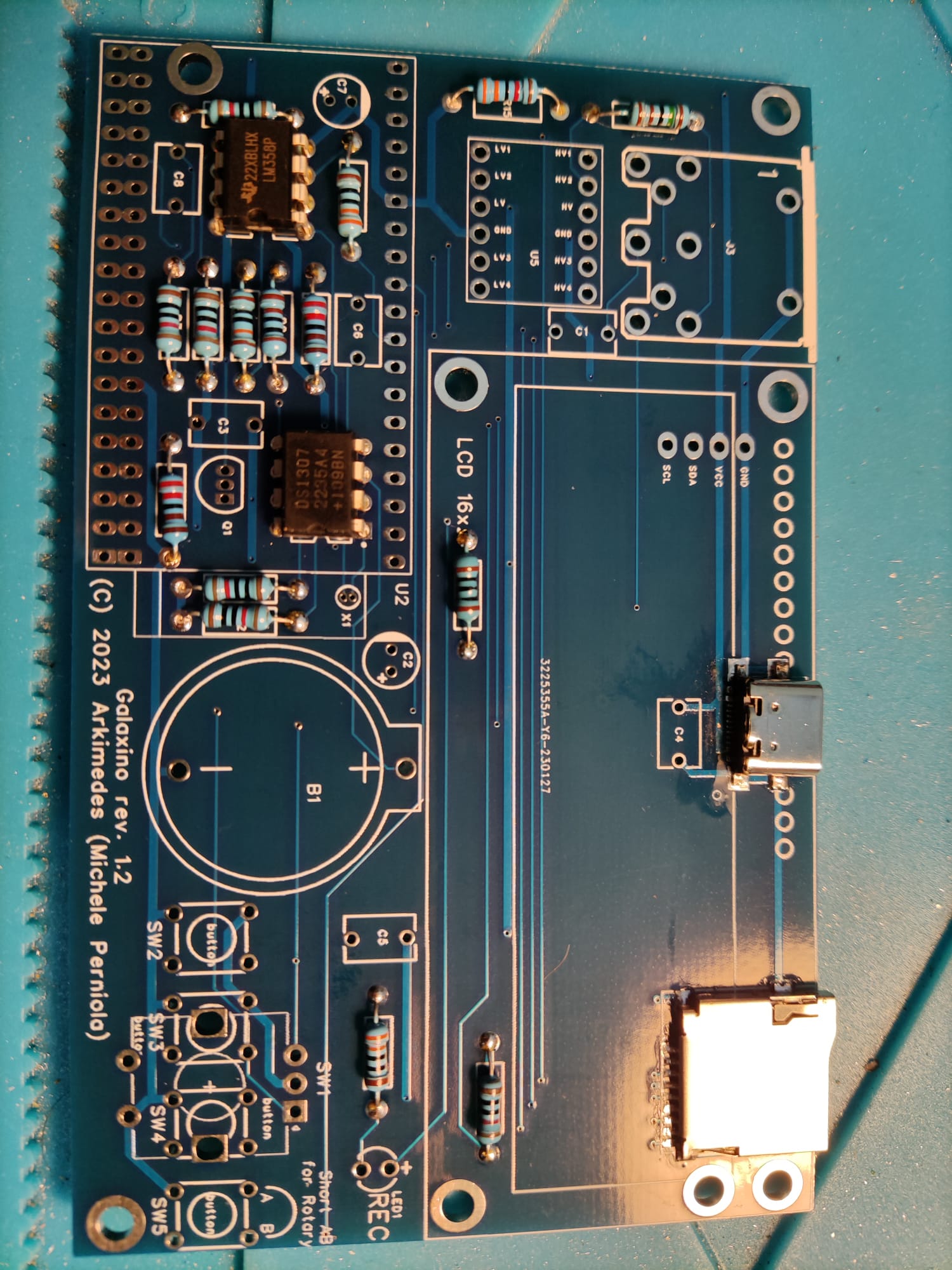
- 2 Assembly of integrated circuits
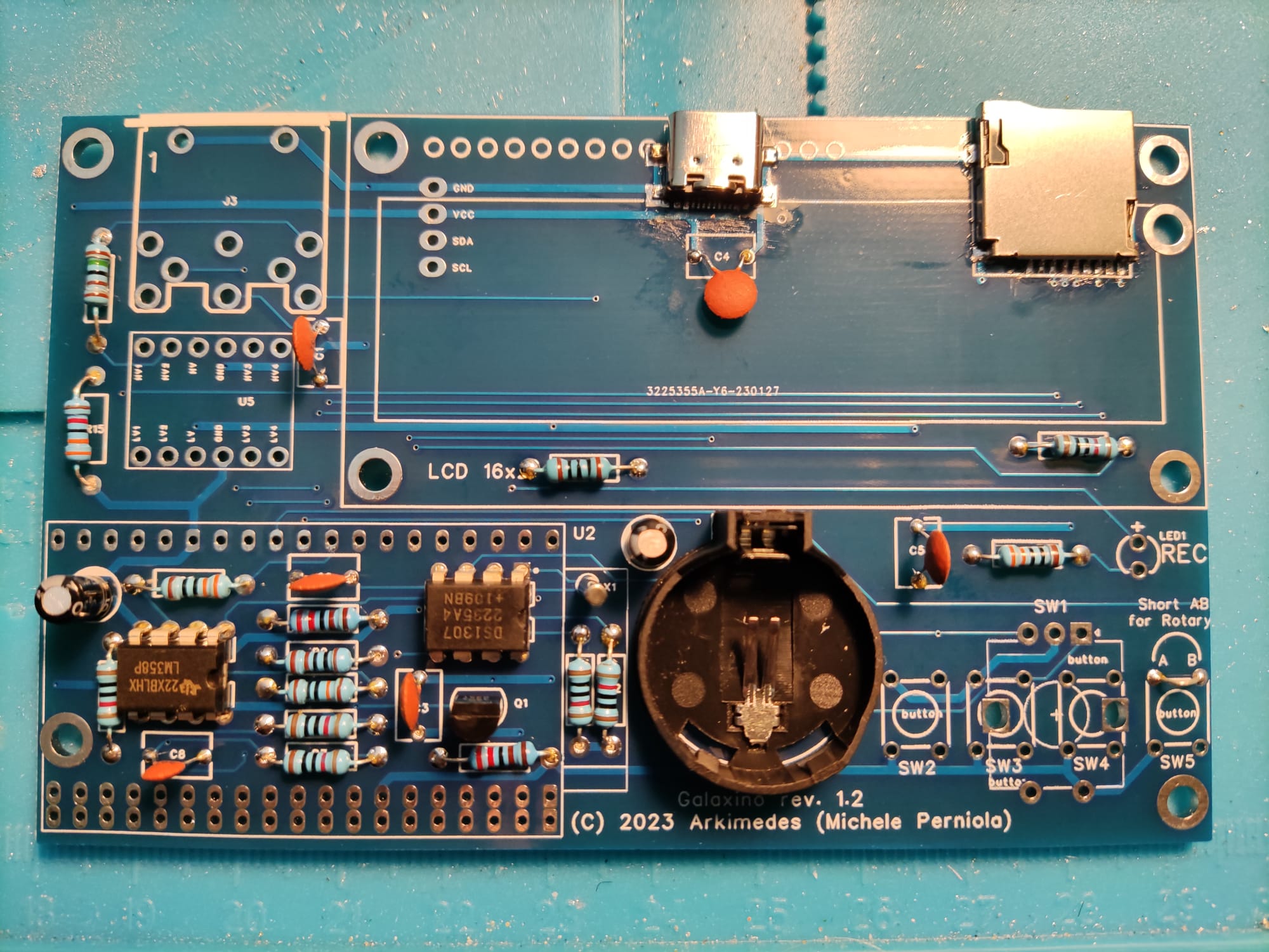
- 3 Assembly of capacitors, transitor, oscillator crystal, battery holder
- 4 Assembly of sockets, level converter, rotary switch and led
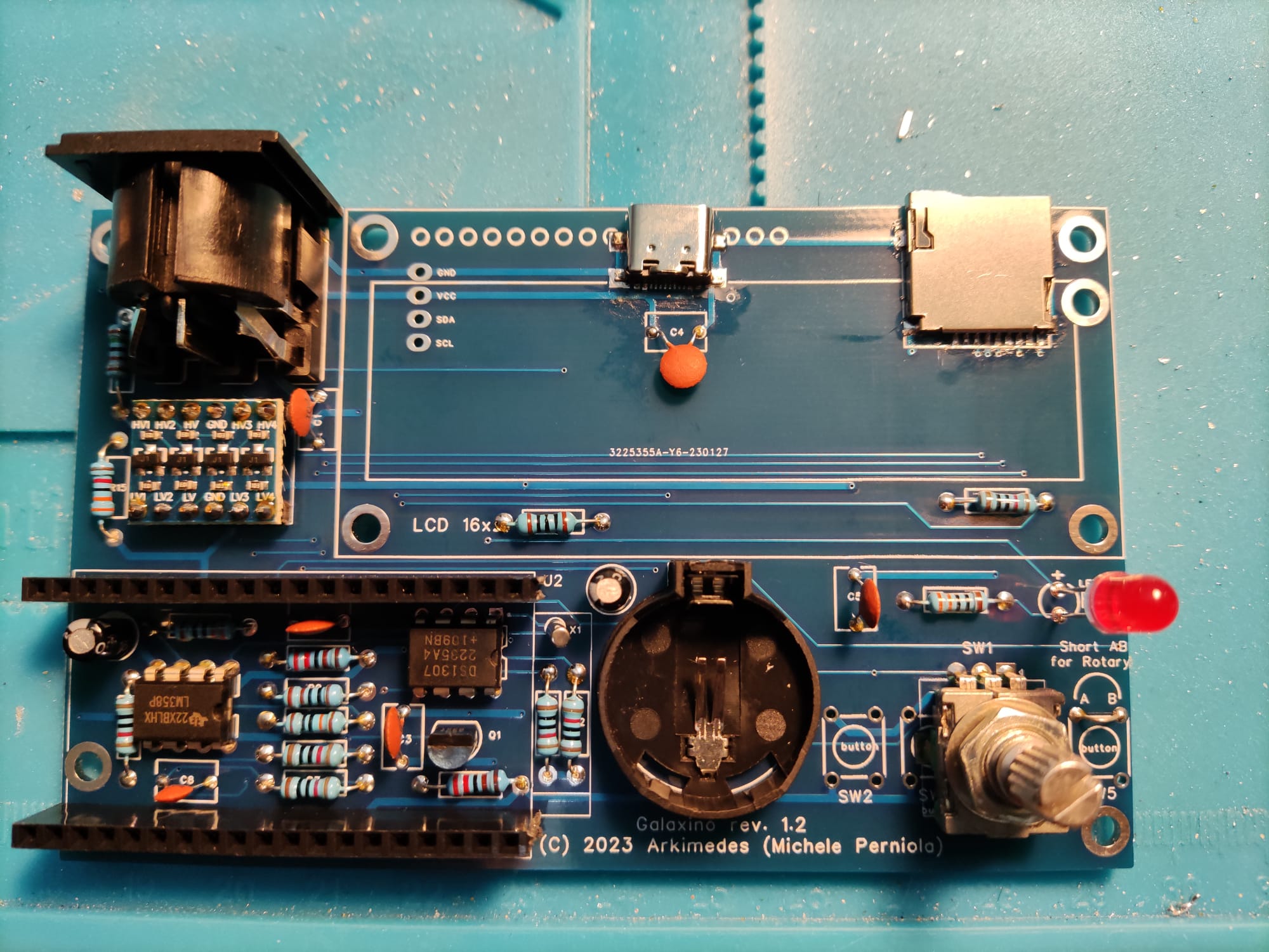
- 5 Assembly of LCD display
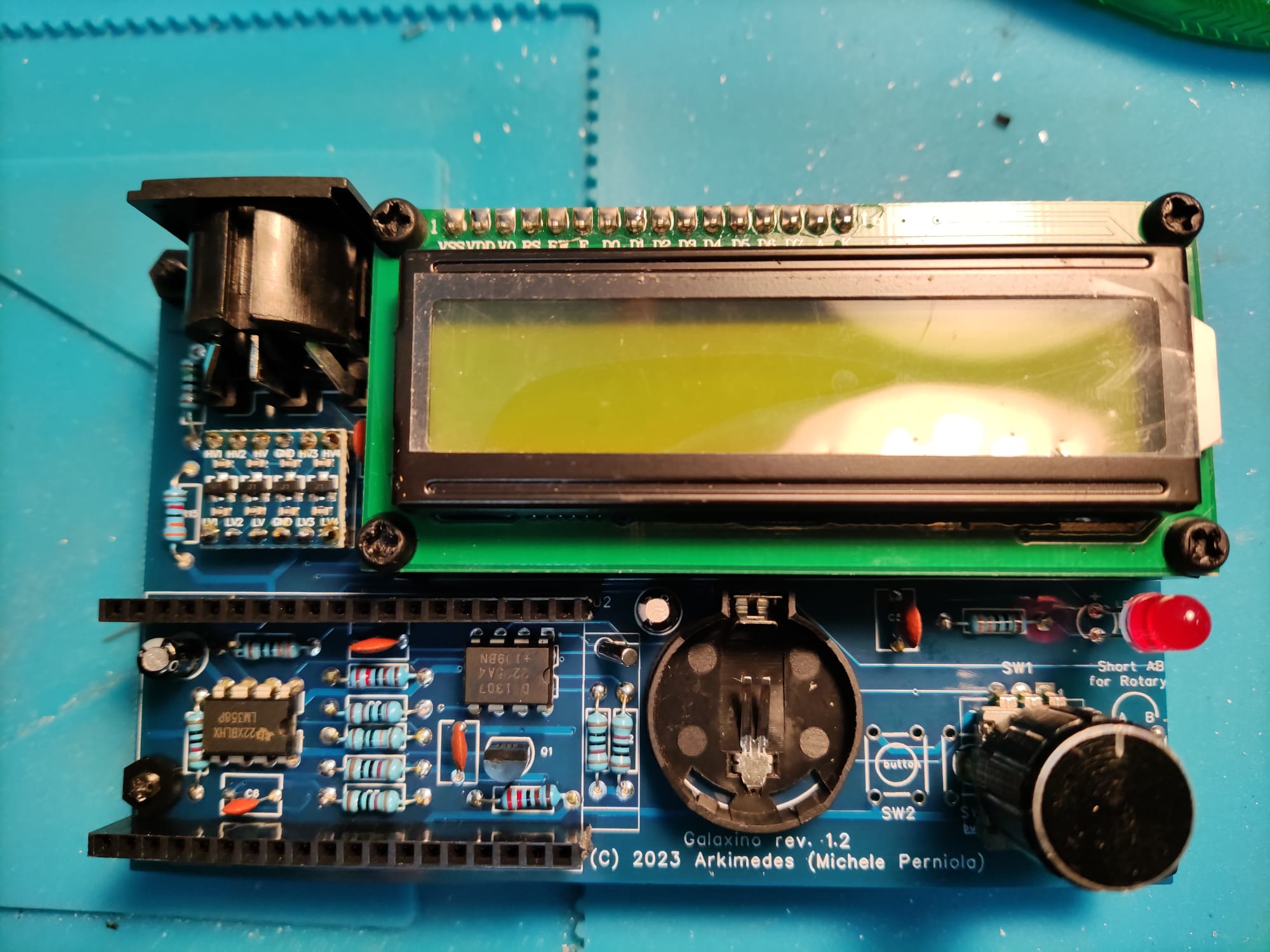
- 6 Assembly of CPU and battery. Complete!
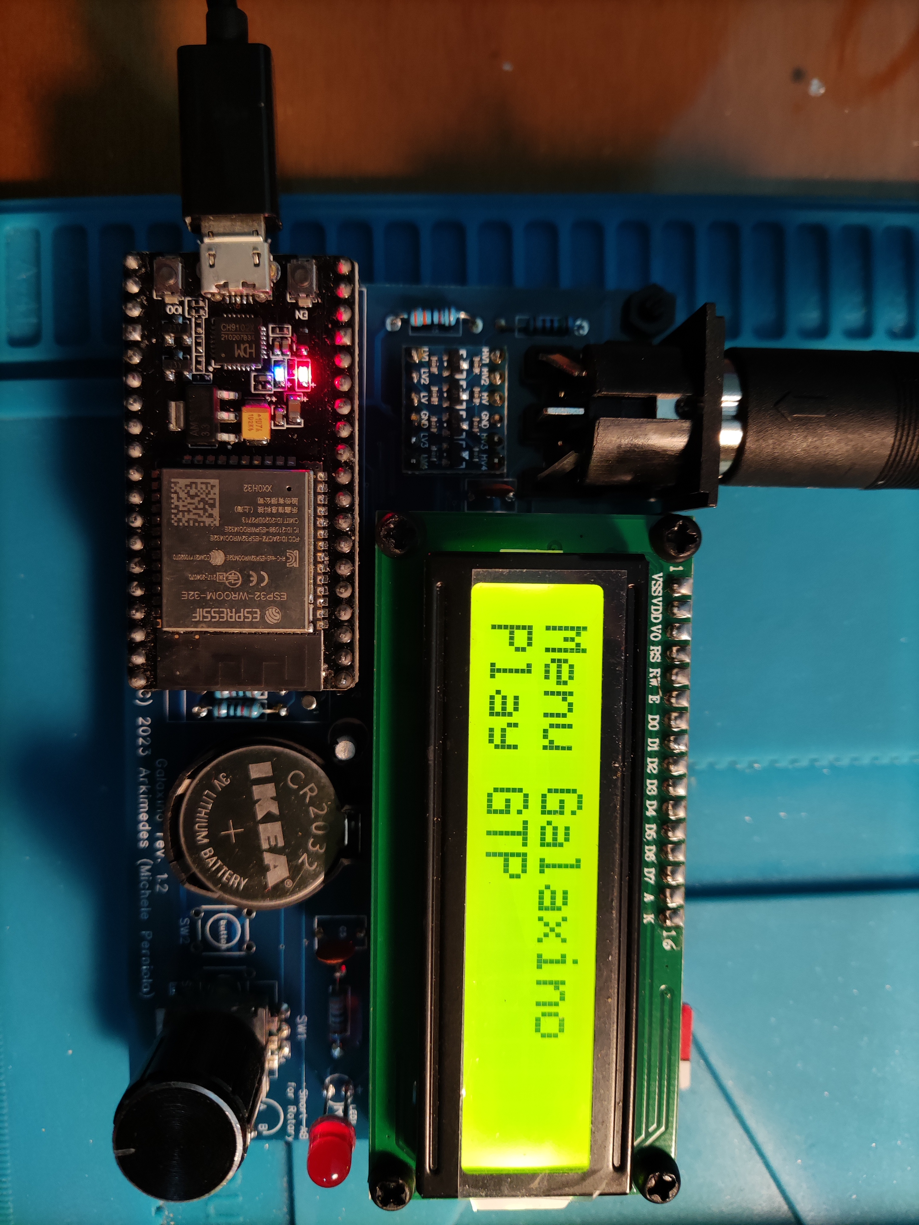
If you have already flashed a recent firmware, then firmware releases are available at: https://github.com/mikyjazz/TheGalaxino/releases
As newer firmware can self update, all you need to do is drop the firmware.bin file onto the root of the SD Card and select the firmware update option from the options menu.
