This code example demonstrates the usage of PIC16F15276 microcontroller together with MCP79410 Real-Time Clock/Calendar (RTCC) module for alarm feature implementation in the embedded applications, where the PIC16F15276 microcontroller communicates with MCP79410 module through serial communication interface like I2C.
The PIC16F152xx family of microcontrollers are available in the general purpose device packages for various embedded applications. The PIC16F15276 simplified feature set includes: Peripheral Pin Select (PPS), digital communication peripherals, timers, Enhanced Universal Synchronous Asynchronous Receiver Transmitter (EUSART). In real time applications, EUSART can be configured as a full-duplex asynchronous system or half-duplex synchronous system. Full-Duplex mode is useful for communications with peripheral systems, such as CRT terminals and personal computers. Half-Duplex Synchronous mode is intended for communications with peripheral devices, such as Analog-to-Digital (A/D) or Digital-to-Analog (D/A) integrated circuits, serial EEPROMs or other microcontrollers. Several embedded applications use I/O expander to add the additional I/O pins required for the main microcontroller while interfacing standalone IC modules, display modules, for various features implementation. The Master Synchronous Serial Port (MSSP) module is a serial interface useful for communicating with other peripheral or microcontroller devices. These peripheral devices may be serial EEPROMs, shift registers, display drivers, A/D converters, etc. The MSSP module can operate in one of two modes:
- Serial Peripheral Interface (SPI)
- Inter-Integrated Circuit (I2C)
The Inter-Integrated Circuit (I2C) bus is a multi-host serial data communication bus. Devices communicate in a host/client environment where the host devices initiate the communication. A client device is controlled through addressing. The I2C bus specifies two signal connections:
- Serial Clock (SCL)
- Serial Data (SDA)
Both the SCL and SDA connections are bidirectional open-drain lines, each requiring pull-up resistors for the supply voltage. Pulling the line to ground is considered a logical zero and letting the line float is considered a logical one. This code example demonstrates the implementation of Real-Time Clock with alarm feature using MSSP, EUSART and I2C peripherals of the PIC16F15276 microcontroller.
- Configuring the MCP794XX RTCC Family
- A Complete Electronic Watch Based on MCP79410 I2C RTCC
- Using the Alarm Feature on the MCP79410 RTCC to Implement a Delayed Alarm
- PIC16F15276 Product Page
- PIC16F152xx Family Product Brief
- PIC16F15244 Code Examples on GitHub
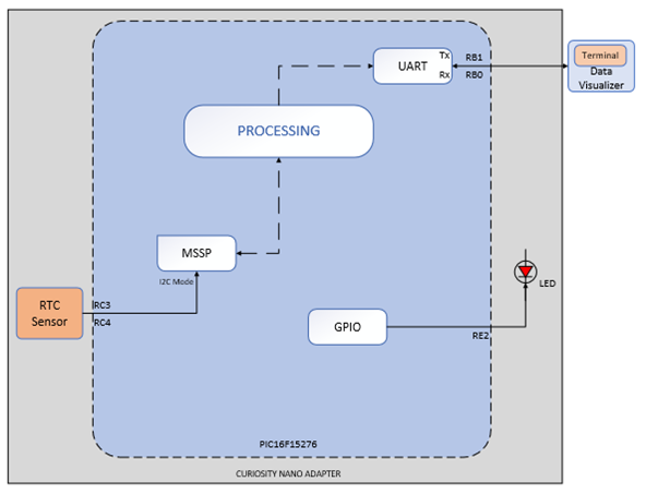
In this code example, the user inputs the timestamp data to which they prefer to set the real-time clock, through the UART serial communication interface. In addition to this, the user can also provide the timestamp for the alarm. The RTCC module provides the user the feature to set two alarms. The PIC16F15276 microcontroller, communicates the timestamp received from the user to RTCC module through the I2C interface.
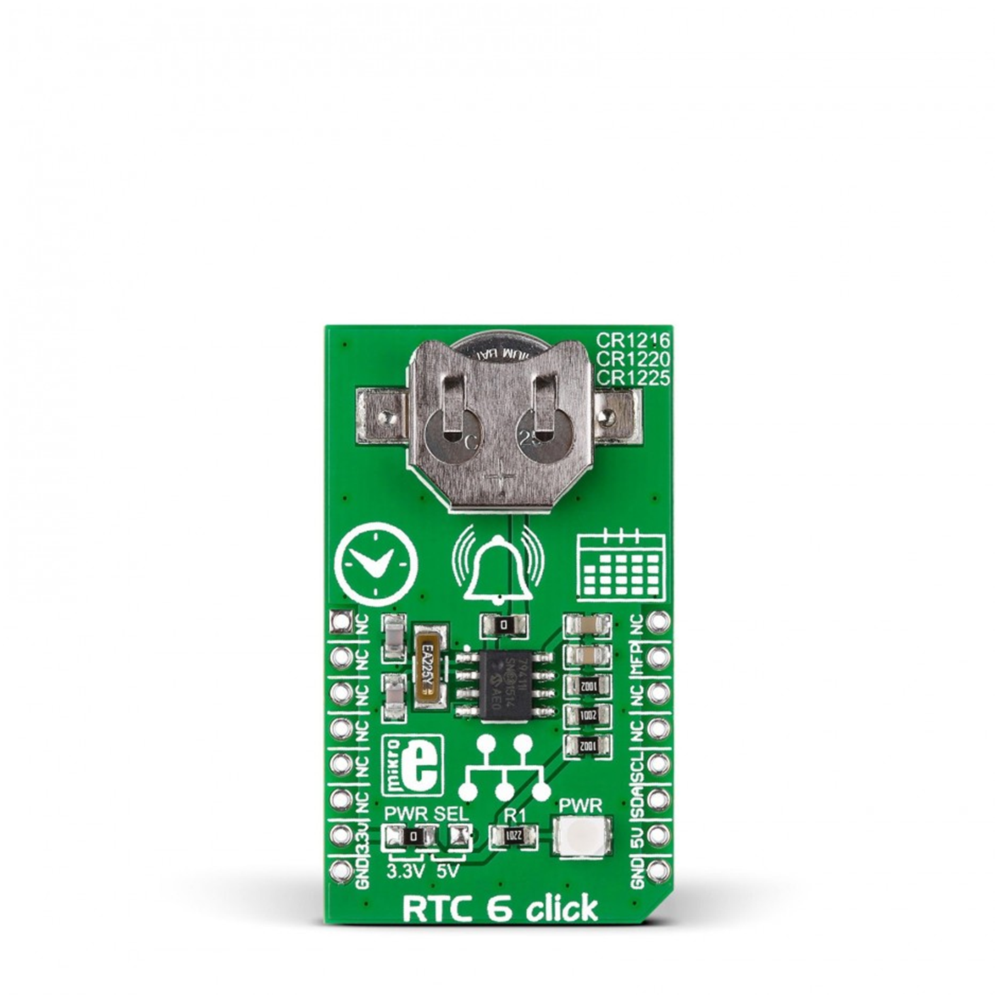
For the ease of demonstration, this code example uses PIC16F15276 Curiosity Nano Development board and RTC 6 Click from MikroElektronika for the Real-Time Clock with alarm feature implementation. There are multiple application that need time measurement which require an RTCC module. RTC 6 Click is based on Microchip's MCP79410, which offers a feature-rich RTCC that incorporates EEPROM, SRAM, unique ID, and timestamp. The RTC 6 Click board is powered-up by an on-board coin cell.
The microcontroller receives the user command and verifies the length of the input and sets the respective values for the real-time clock using the I2C interface..
RTC 6 Click carries Microchip’s MCP79410 Real-Time Clock/Calendar IC with a built-in 64 bytes of battery backed SRAM and an additional 1 Kbit of EEPROM. 64 bits of protected EEPROM requires an unlock sequence to be unlocked, which makes it suitable for storing a unique ID or other critical information. RTC 6 Click tracks hours, minutes, seconds, days, months, years, and weekdays, with leap year compensation until the year 2399. The clock frequency is derived from an on-board 32.768KHz crystal oscillator. Backup power is supplied by a coin-cell Lithium battery. RTC 6 Click communicates with the target board microcontroller through the mikroBUS I2C interface (SCL, SDA) along with a multifunction pin (MFP, in place of default mikroBUS^TM^ INT pin). The multifunctional pin (MFP) can be configured as an alarm, a square wave frequency output, or a general purpose output. The board is designed to use 3.3V.
The RTC 6 Click from MikroElektronika is used for maintaining the timestamp and the alarm time.
Terminal window shows the timestamp values set or read from RTC 6 Click in decimal and epoch clock format.
Microchip’s free IDE, compiler and graphical code generators are used throughout the application firmware development. Following are the tools used for this demo application:
- MPLAB^®^ X IDE v6.15.0 or newer
- XC8 Compiler v2.41.0
- MPLAB Code Configurator (MCC) v5.3.7
- Microchip PIC16F1xxxx Series Device Support 1.20.366 or newer
- EUSART MCC Melody Driver 7.1.4
- I2C Host MCC Melody driver 1.0.4
Note: For running the demo, the installed tool versions should be same or later. This example is not tested with previous versions.
This example is comprised of a single firmware.
The firmware used the EUSART peripheral for communicating with the user to receive timestamps. Upon detection of a valid timestamp, the microcontroller sends the timestamp command to the RTC sensor over I2C interface. It also allows the user to set an alarm time. If the alarm timestamp is provided, then the respective command is provided to the sensor over I2C. On matching the alarm timestamp the on-board LED turns on.
The following figure consists of RTC 6 Click, Curiosity Nano base for click boards and PIC16F15276 Curiosity Nano Evaluation Kit. The figure shows the detailed information about the hardware setup. The RTC 6 Click is interfaced with PIC16F15276 microcontroller using curiosity nano adapter slot 2.
Real-Time Clock demonstration needs input in epochs format. Also, the output data is in epoch format on the terminal. The required hardware connections are shown in the preceding figure.
In case of device addressing, the control byte is the first byte received following the Start condition from the host device. The control byte begins with a control code '1101' for SRAM/RTCC register read/write. The last bit of the control byte defines the operation to be performed, with 1 for read and 0 for write operation. The combination of the 4-bit control code and the three chip select(CS) bits will define the slave address as shown in the below figure.
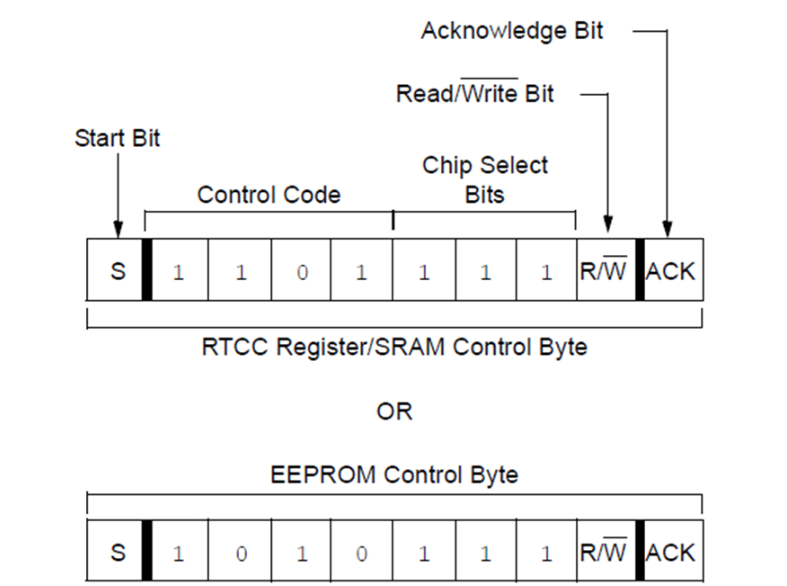
Figure 4: Control Byte Register
- Assemble the hardware as shown in the Hardware Setup. Power up the Curiosity Nano device using a micro-USB cable
- Download the firmware available from the GitHub page link
- Build the project using the latest version of tools as mentioned in the Software Tools section and load the generated hexadecimal file in to the PIC16F15276 microcontroller
- After running the program, the initial display will ask which functionality to perform. Hence, the text/data that is displayed on the terminal is as shown in figure below.
- If Read the current stamp functionality is selected, the RTC 6 Click will provide the time previously stored in the battery back SRAM
- The functionality to set the time stamp will allow the user to set the time of his choice
- The RTC 6 Click is designed to operate using a 32.768kHz crystal oscillator, which starts the clock counters and does provide the accurate time if it is read after setting the time previously
- For setting the alarm, the input array of characters must include epoch timestamp for the alarm to set
The Real-Time Clock with alarm feature can be executed with a range of controller families that have less memory and do not support internal RTC feature. The RTC 6 Click supports a two alarm feature with inbuilt Microchip's MCP47910 device, which enables the user to set the timestamp along with two alarms. This code example demonstrates the usage of PIC16F15276 microcontroller together with Microchip’s MCP47910 RTCC module to make a real-time clock with an alarm feature.
MPLAB Code Configurator (MCC) is is a graphical programming environment that generates seamless, easy to understand C code to give a head start to the project, saving the designer’s time to initialize and configure all the modules, and to go through the data sheets. Using an instructive interface, it enables and configures all peripherals and functions specific to the application requirements.
Start by creating a new Project and open MCC
- Go to File > New Project
- Select Microchip Embedded > Standalone Project
- Enter the device name. In this case, select PIC16F15276 device
- Name the project
- Launch MCC tool by navigating to Tools > Embedded > MPLAB Code Configurator v4: Open/Close. Alternatively, click the MCC icon to launch the MCC tool.
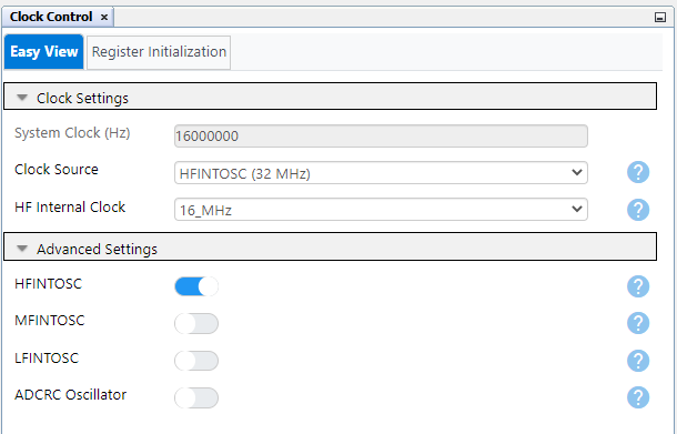
Open Clock Control setup present under System dropdown menu in Project Resources tab. Host and the client device will be configured with same configuration as given below.
- Set Clock Source as HFINTOSC
- Set HF Internal Clock as 16_MHz
- Enable low power programming checkbox
The system configuration window of MCC is used for microcontroller oscillator, Watchdog timer and low voltage programming configuration. The Watchdog timer is disabled in the application.
The following figure shows the system configuration setting in MCC tool.
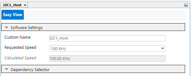
- Serial Protocol: I2C
- Mode: Host
- I2C Clock Frequency: 100 kHz
- Slew Rate Control: Standard Speed
- SDA Hold Time: 100 ns
The curiosity Nano base for click boards mikroBUS slot 2 is used for RTC 6 Click, I/O pins for the same are configured through pin manager section of MCC.
The EUSART peripheral is used by both host and client devices for the communication amongst them.
- Set EUSART Mode to Asynchronous
- Enable EUSART, Transmit & Receive checkbox
- Set Baud Rate to 9600
- Set Transmission and Reception bits to 8bit
- Select checkbox for Redirect STDIO to USART
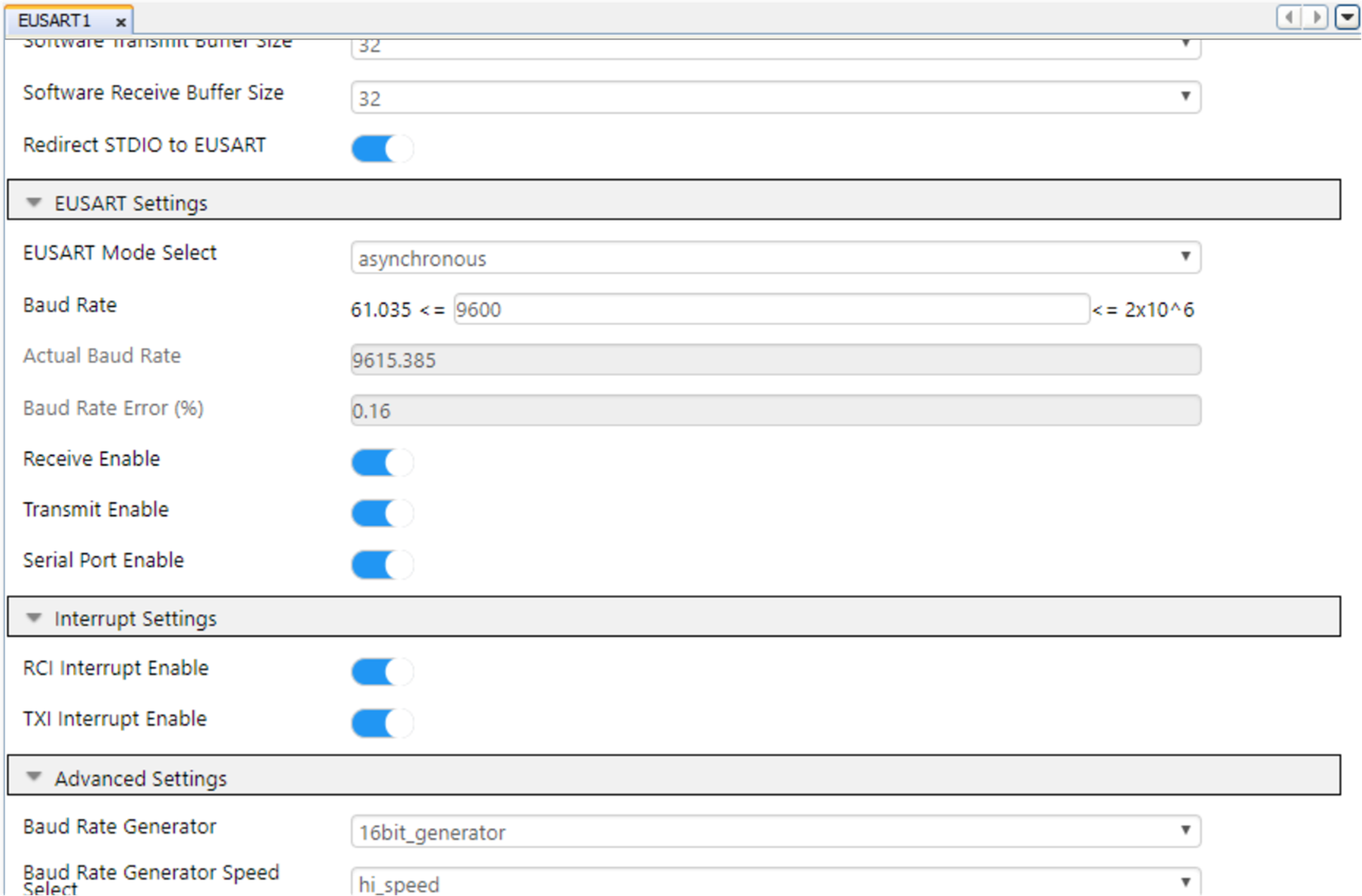
Figure 7: EUSART Configuration
Pre-configured data streamer file is available with the firmware package. The below steps given for data visualizer configuration use these files to prepare the setup.
- Configure the serial port for communication with the Curiosity Nano Adapter Board
- Set the baud rate to 115200, parity to none and stop bits to 1
- Ensure the DTR option and Open Terminal options both are checked and RTS is unchecked
- Configure Terminal for visualizing the data values in real-time
NOTE: Refer Data Visualizer user guide for more information.

