
This repository contains examples of bare metal source code for DAC as described in TB3235 - Using 10-Bit DAC for Generating Analog Signals document from Microchip. The repository contains an Atmel Studio Solution (AVR-DA128_DAC_Examples.atsln) with four projects inside, one project for each illustrated use case.
Use cases:
- Generating Constant Analog Signal Using 10-Bit DAC (Generating_Constant_Signal_Example project)
- Use case description: Initialize the DAC, set the 2.048V internal voltage reference for the DAC peripheral, set the DAC to output a specific constant voltage.
- Result: A 1.2V constant analog signal will be available on the DAC output external pin (PD6).
- Generating Sine Wave Signal Using 10-Bit DAC (Generating_Sine_Wave_Signal_Example project)
- Use case description: Initialize the DAC, set the 2.048V internal voltage reference for the DAC peripheral, set the DAC to output in a loop the samples of a sine wave.
- Result: A 100Hz sine wave will be available on the DAC output external pin (PD6).
- Reading the DAC Internally with the ADC (Reading_DAC_with_ADC_Example project)
- Use case description: Initialize the DAC and ADC, set the DAC peripheral as input for the ADC, set the 2.048V internal voltage reference for the DAC and ADC peripherals, increment the DAC output and read it with the ADC for each step.
- Result: The value read by the ADC will modify according to the changes of the DAC input value.
- Generating Amplitude Modulated Signal Using 10-Bit DAC (Generate_Amplitude_Modulated_Signal_Example project)
- Use case description: Initialize the DAC with external voltage reference and link the signal that must be modulated to the external reference pin (PD7). The AVR core will continuously change the Data (DACn.DATA) register to create a modulated signal.
- Result: The resulting modulated signal will be available on the DAC output external pin (PD6).
More details and code examples on the AVR128DA48 can be found at the following links:
- TB3235 - Using 10-Bit DAC for Generating Analog Signals
- AVR128DA48 Product Page
- AVR128DA48 Code Examples on GitHub
- AVR128DA48 Project Examples in START
- Microchip Studio 7.0.2397 or newer (Microchip Studio for AVR® and SAM Devices)
- AVR-Dx 1.0.18 or newer Device Pack
- AVR128DA48 Curiosity Nano (DM164151)
Generating Constant Analog Signal Using 10-Bit DAC
The AVR128DA48 Curiosity Nano Development Board is used as test platform.

The following configurations must be made for this project:
VREF:
- Select the 2.048V internal voltage reference for the DAC peripheral
- Set the Voltage Reference in Always On mode
DAC0:
- Enable DAC
- Enable the output buffer
- Enable Run in Standby mode
- Disable digital input buffer and the pull-up resistor for the DAC output external pin (PD6)
Generating Constant Analog Signal Using 10-Bit DAC
-
Connect the board to the PC.
-
Open the AVR-DA128_DAC_Examples.atsln solution in Atmel Studio
-
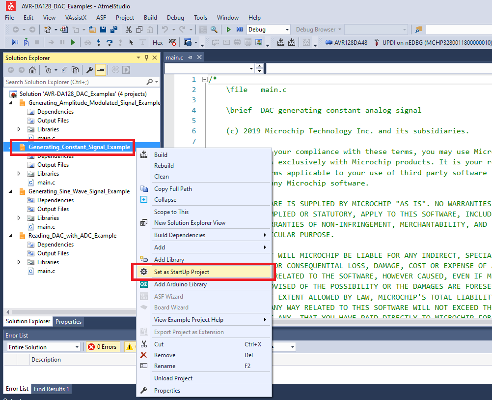
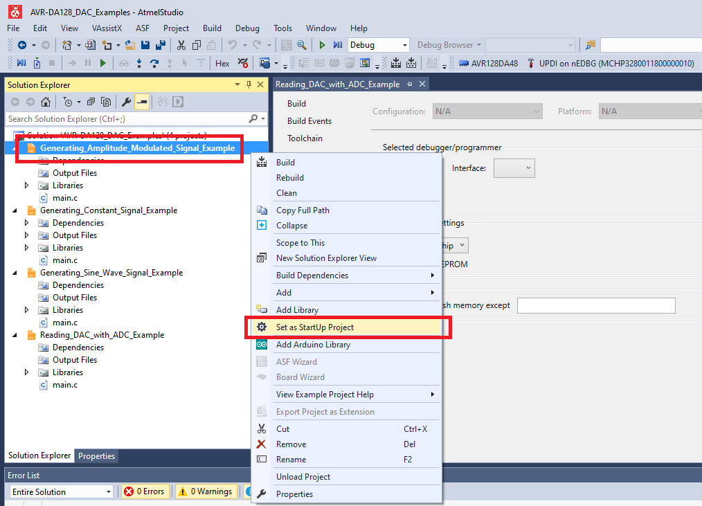
Set Generating_Constant_Signal_Example project as StartUp project:
-
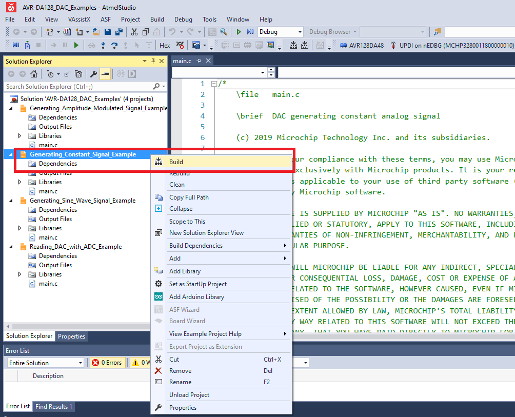
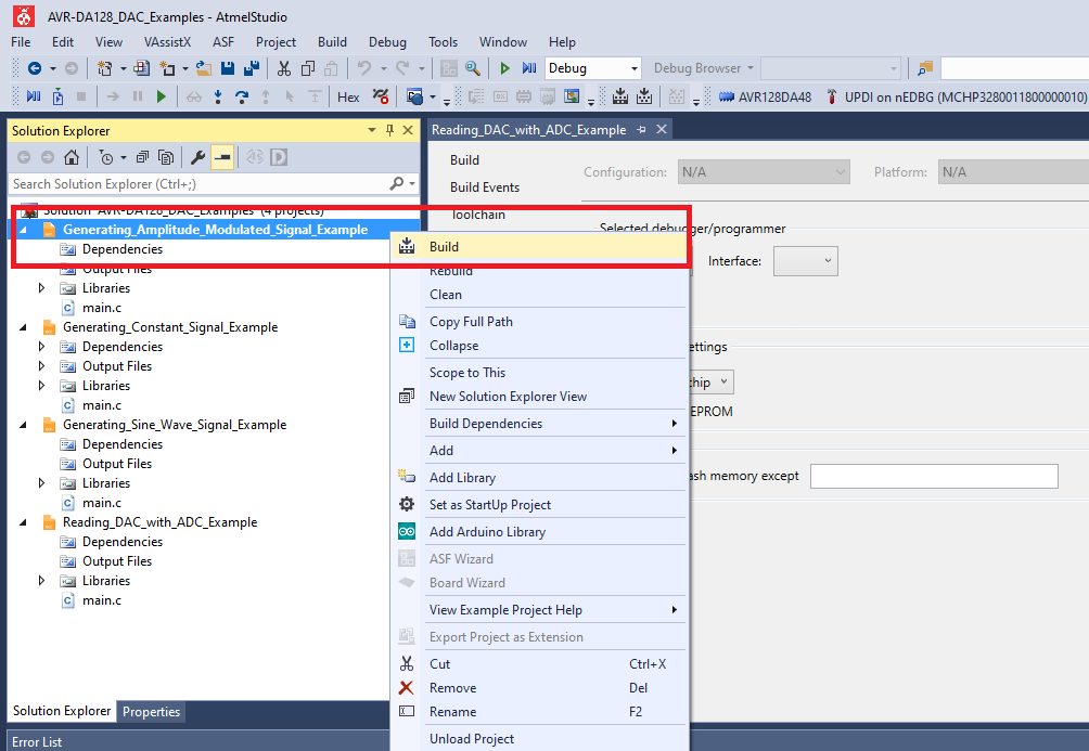
Build the Generating_Constant_Signal_Example project: right click on Generating_Constant_Signal_Example and select Build
-
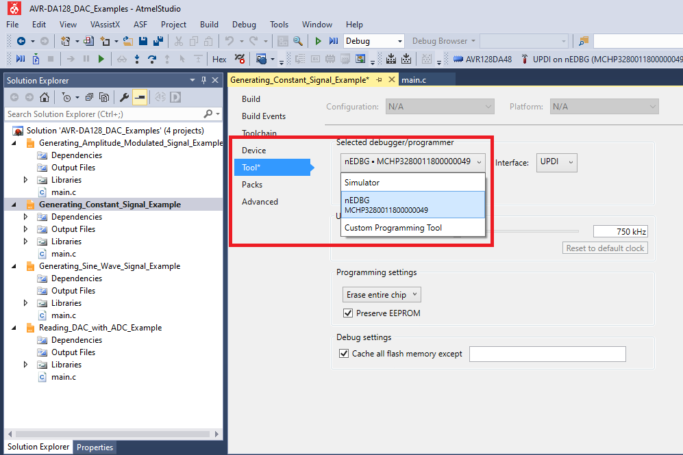
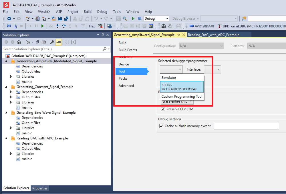
Select the AVR128DA48 Curiosity Nano on-board debugger in the Tool section of the AVR-Dx_Bootloader project settings:


- Right click on the project and click Properties;
- Click Tool tab on the left panel, select the corresponding debugger and save the configuration (Ctrl + S)

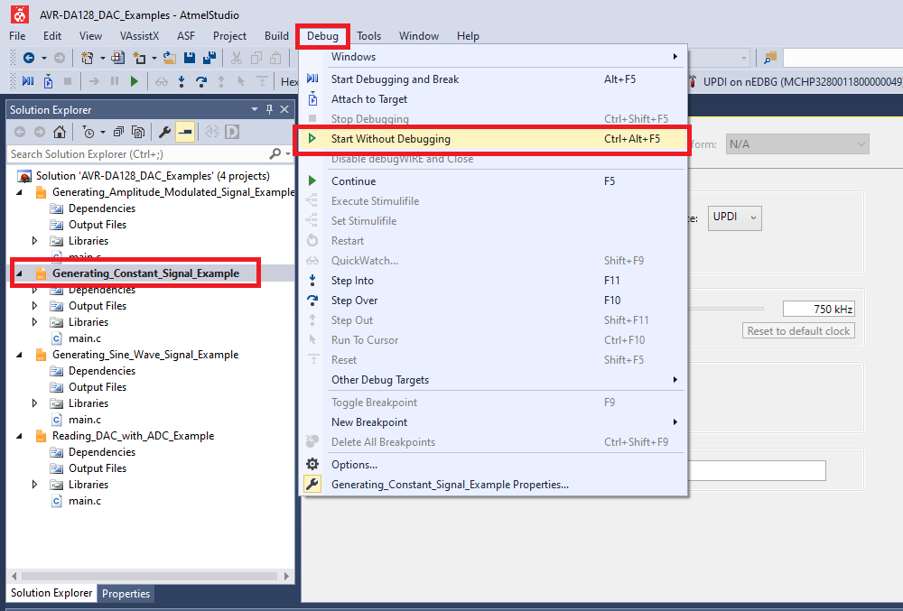
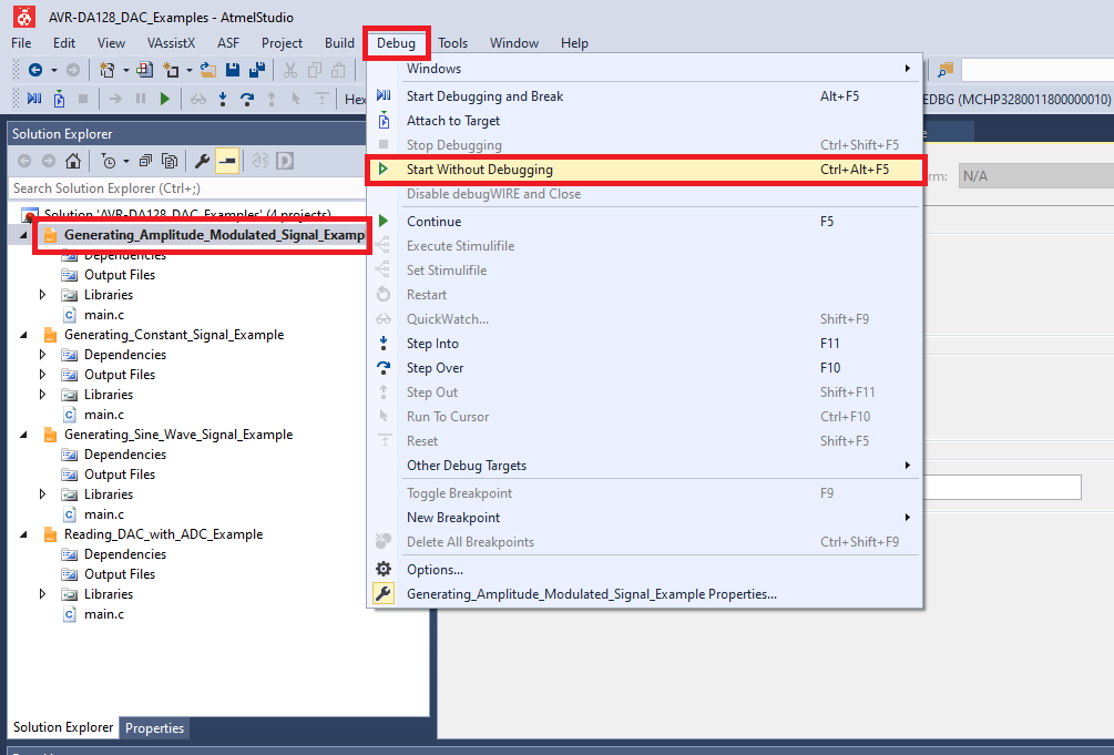
- Program Generating_Constant_Signal_Example project to the board: select Generating_Constant_Signal_Example project and click Start Without Debugging:

Results
PD6 - Constant analog signal (1.2V) on Channel 0 (black) below

Generating Sine Wave Signal Using 10-Bit DAC
The AVR128DA48 Curiosity Nano Development Board is used as test platform.
The following configurations must be made for this project:
VREF:
- Select the 2.048V internal voltage reference for the DAC peripheral
- Set the Voltage Reference in Always On mode
DAC0:
- Enable DAC
- Enable the output buffer
- Enable Run in Standby mode
- Disable digital input buffer and the pull-up resistor for the DAC output external pin (PD6)
Generating Sine Wave Signal Using 10-Bit DAC
-
Connect the board to the PC.
-
Open the AVR-DA128_DAC_Examples.atsln solution in Atmel Studio
-
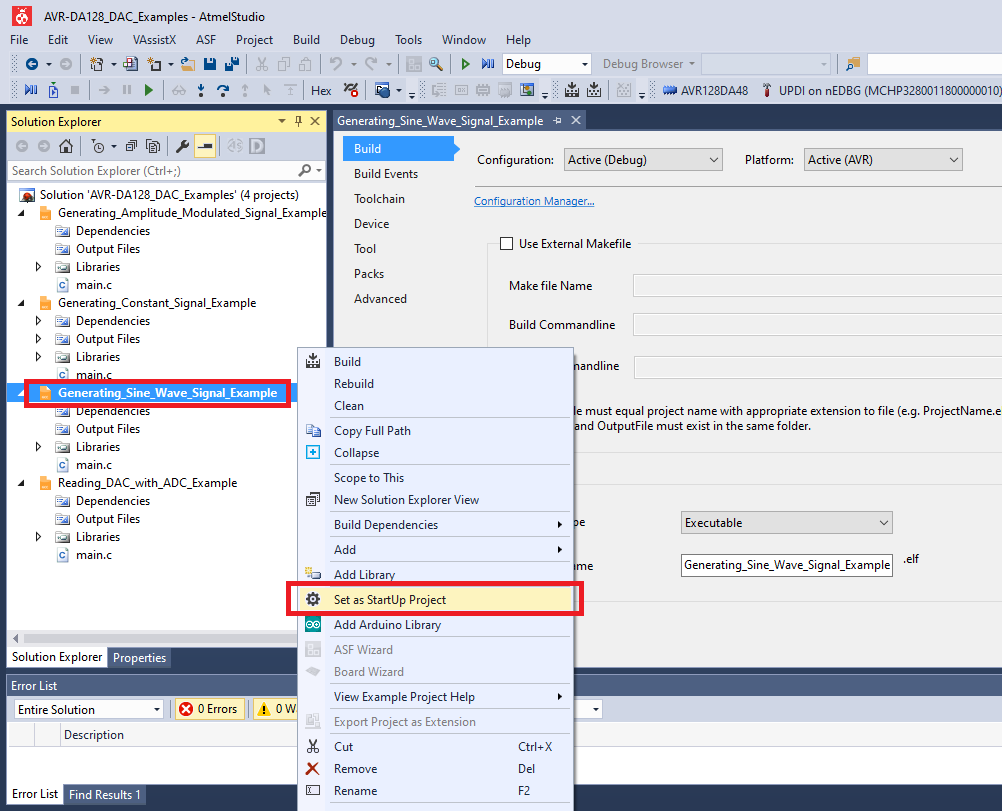
Set Generating_Sine_Wave_Signal_Example project as StartUp project:
-
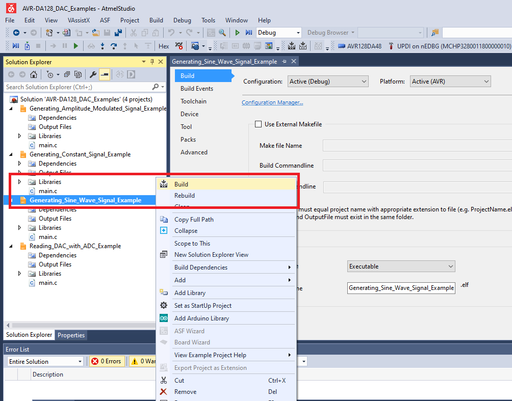
Build the Generating_Sine_Wave_Signal_Example project: right click on Generating_Sine_Wave_Signal_Example and select Build
-
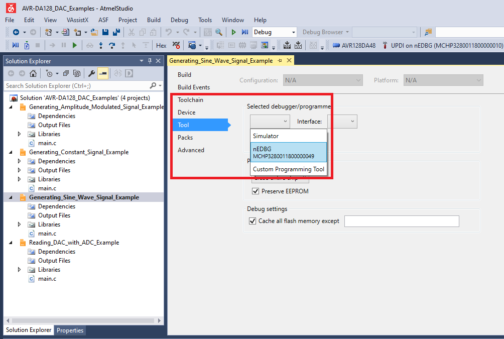
Select the AVR128DA48 Curiosity Nano on-board debugger in the Tool section of the Generating_Sine_Wave_Signal_Example project settings:


- Right click on the project and click Properties;
- Click Tool tab on the left panel, select the corresponding debugger and save the configuration (Ctrl + S)

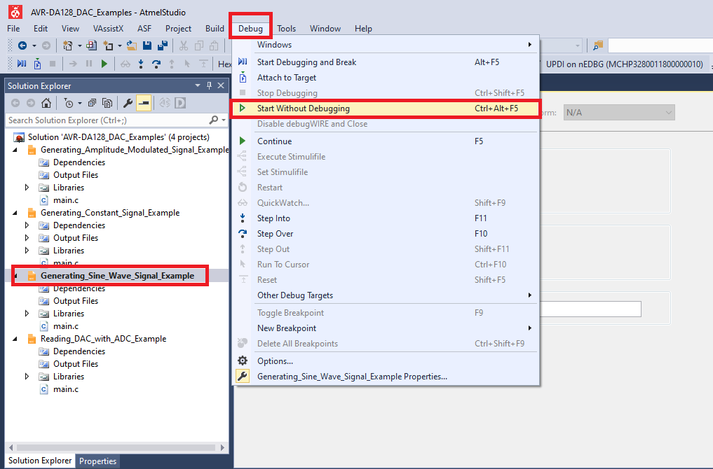
- Program Generating_Sine_Wave_Signal_Example project to the board: select Generating_Sine_Wave_Signal_Example project and click Start Without Debugging:

Results
PD6 - Sine wave on Channel 0 (black) below

Reading the DAC Internally with the ADC
The AVR128DA48 Curiosity Nano Development Board is used as test platform.
The following configurations must be made for this project:
VREF:
- Select the 2.048V internal voltage reference for the DAC peripheral
- Select the 2.048V internal voltage reference for the ADC peripheral
- Set the Voltage References in Always On mode
DAC0:
- Enable DAC
ADC0:
- Enable ADC
- Select 12-bit resolution
- Select DIV2 prescaler
- Set the DAC peripheral as input for the ADC
Reading the DAC Internally with the ADC
-
Connect the board to the PC.
-
Open the AVR-DA128_DAC_Examples.atsln solution in Atmel Studio
-
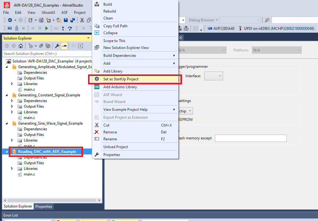
Set Reading_DAC_with_ADC_Example project as StartUp project:
-
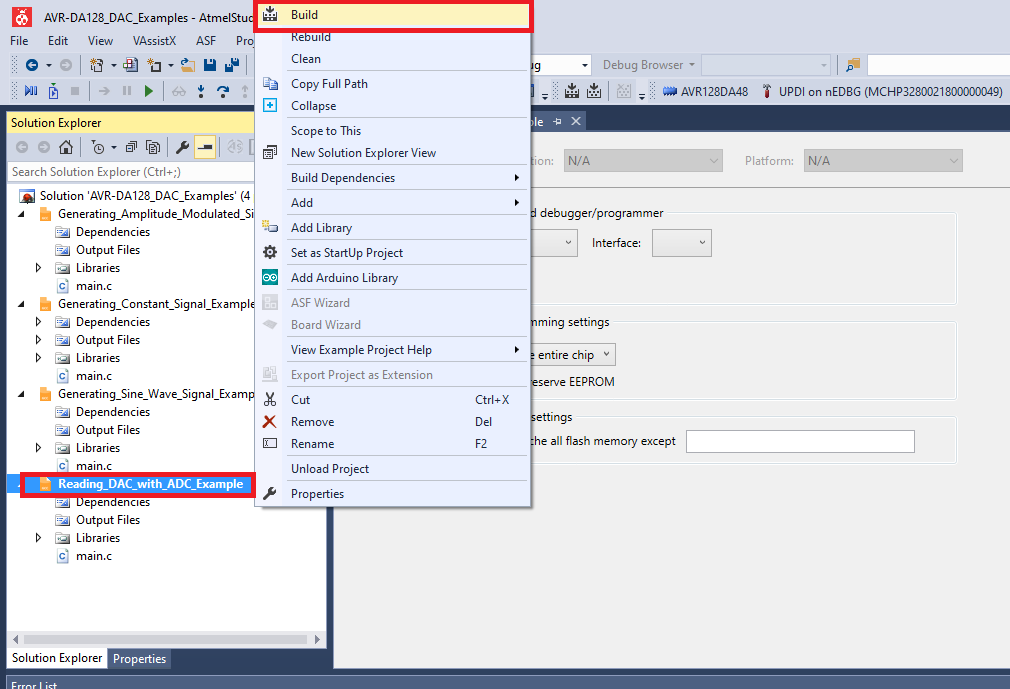
Build the Reading_DAC_with_ADC_Example project: right click on Reading_DAC_with_ADC_Example and select Build
-
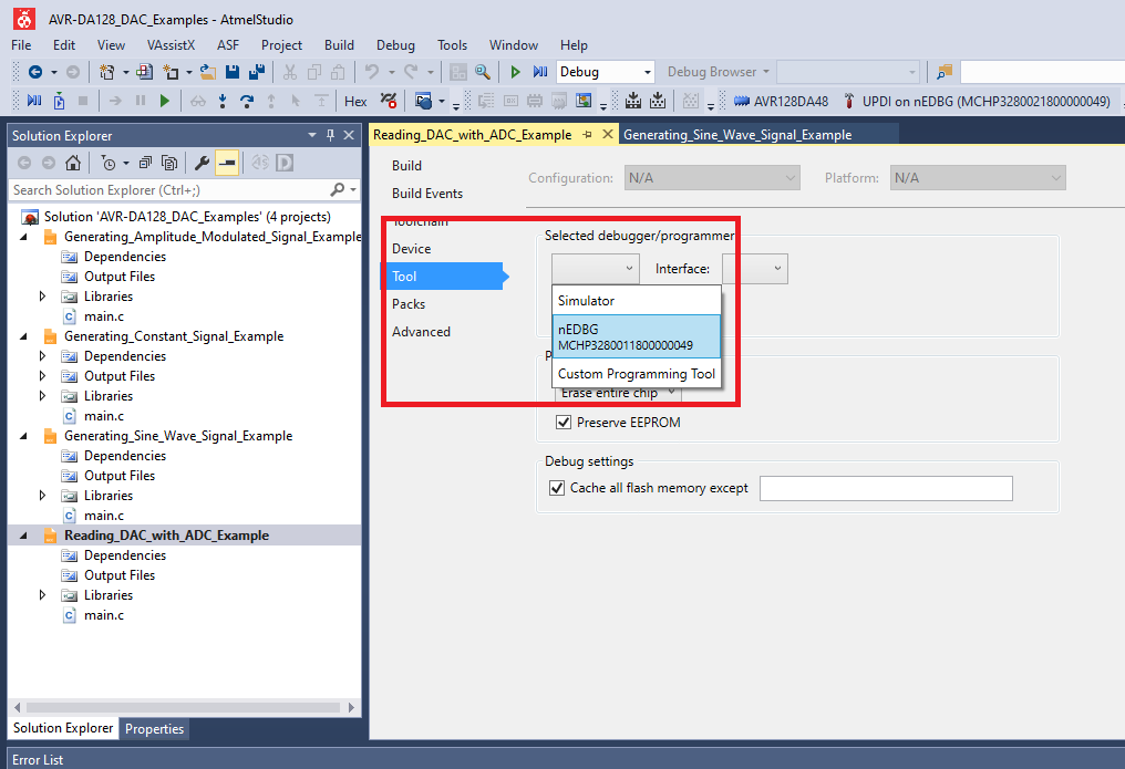
Select the AVR128DA48 Curiosity Nano on-board debugger in the Tool section of the Reading_DAC_with_ADC_Example project settings:


- Right click on the project and click Properties;
- Click Tool tab on the left panel, select the corresponding debugger and save the configuration (Ctrl + S)

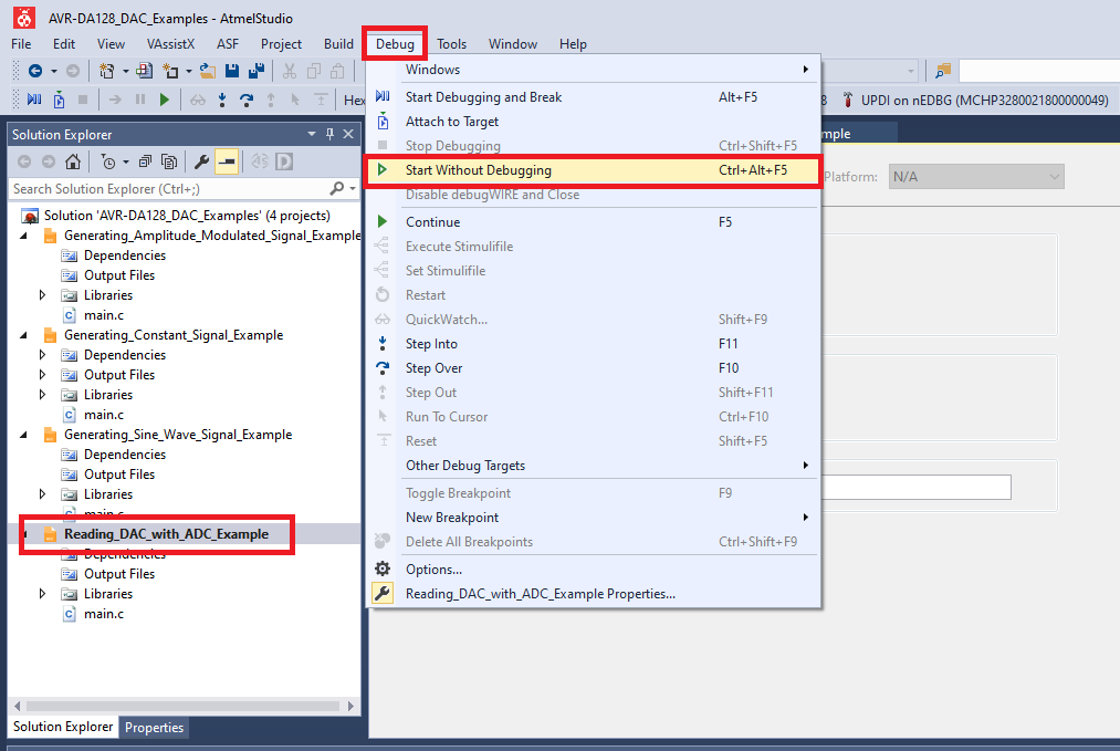
- Program Reading_DAC_with_ADC_Example project to the board: select Reading_DAC_with_ADC_Example project and click Start Without Debugging:

Results
Theoretical results for dacVal = 100

Practical results for dacVal = 100 using Debug Mode

Generating Amplitude Modulated Signal Using 10-Bit DAC
The AVR128DA48 Curiosity Nano Development Board is used as test platform.
The following configurations must be made for this project:
VREF:
- Select the external voltage reference on VREFA pin (PD7) for the DAC peripheral
- Set the Voltage Reference in Always On mode
DAC0:
- Enable DAC
- Enable the output buffer
- Enable Run in Standby mode
- Disable digital input buffer and the pull-up resistor for the DAC output external pin (PD6)
| Pin | Configuration |
|---|---|
| PD7 (VREFA) | Analog Input |
Generating Amplitude Modulated Signal Using 10-Bit DAC
-
Connect the board to the PC.
-
Open the AVR-DA128_DAC_Examples.atsln solution in Atmel Studio
-
Set Generate_Amplitude_Modulated_Signal_Example project as StartUp project:
-
Build the Generate_Amplitude_Modulated_Signal_Example project: right click on Generate_Amplitude_Modulated_Signal_Example and select Build
-
Select the AVR128DA48 Curiosity Nano on-board debugger in the Tool section of the Generate_Amplitude_Modulated_Signal_Example project settings:


- Right click on the project and click Properties;
- Click Tool tab on the left panel, select the corresponding debugger and save the configuration (Ctrl + S)

- Program Generate_Amplitude_Modulated_Signal_Example project to the board: select Generate_Amplitude_Modulated_Signal_Example project and click Start Without Debugging:

Results
External Analog Signal (information signal) on VREFA (PD7) pin - Channel 1 (orange) in the screenshot below
Amplitude Modulated Signal on PD6 - Channel 2 (blue) in the screenshots below


The TB3235 - Using 10-Bit DAC for Generating Analog Signals document provides four use cases for generating analog signals using the 10-bit DAC.