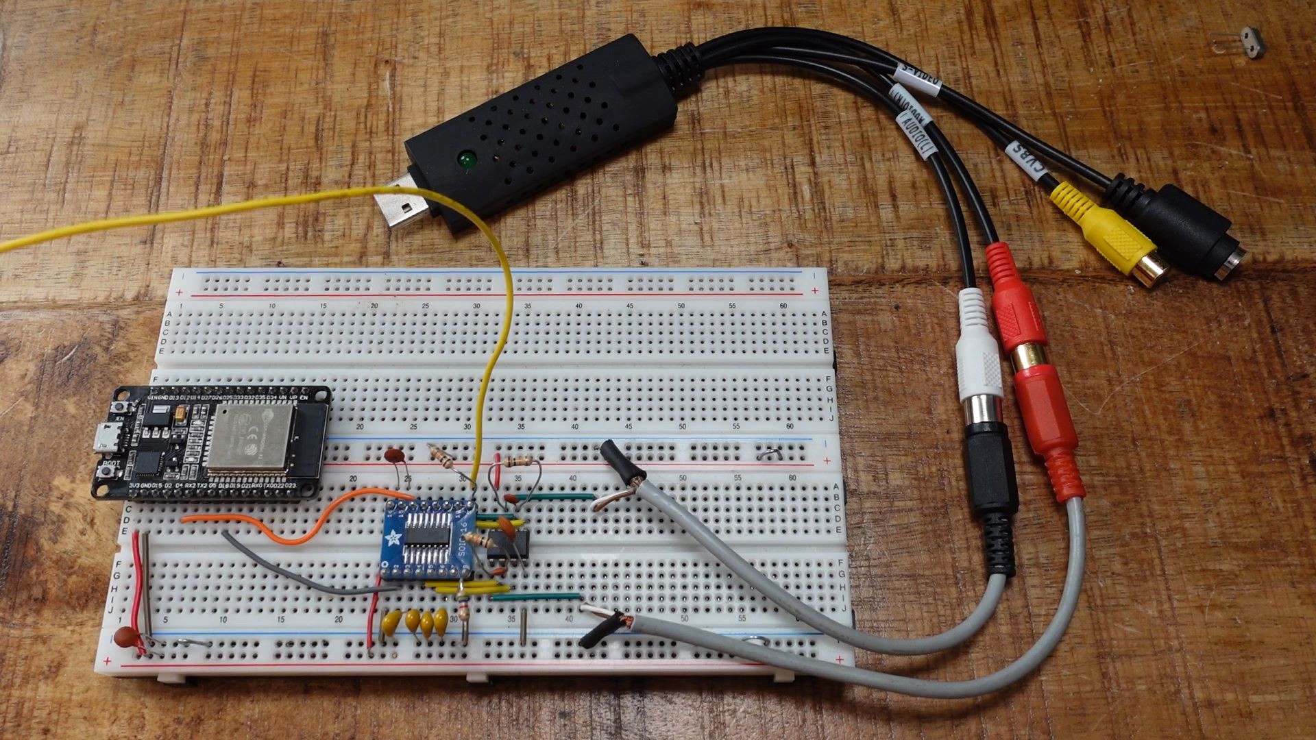
Simple SDR Receiver that can receive frequencies up to approximately 30MHz, if an optional Si5351 clock generator is used. Without this, it receives up to about 20MHz, using the ESP32 clock dividers. The circuit is so simple that it can even be built on a breadboard.
 Tayloe Quadrature Detector circuit on a solderless breadboard
 Circuit on a PCB with USB capture device connected
- ESP32 Development Module
- The circuit on Breadboard or PCB
- Sound card or USB sound capture device with stereo input and a sample rate of at least 48 kbit/s.
- At least 10m or wire as an antenna
- Windows or Linux PC. A Raspberry Pi or similar board might also work, but I didn't test this.
- Etherkit Si5351 Arduino Library (if Si5351 is used)
- Set
#define USE_SI5351 1in the ESP32 sketch if you are using an Si5351. - Flash it to your ESP32 dev module.
- Connect output "I" to the right channel and "Q" to the left channel of your sound card.
- Download and install Quisk
- Make sure that TKinter is installed. If not type
sudo apt install python3-tkorpip install tkinter - Configure the serial port the ESP32 is connected to in the variable openradio_serial_port in .quisk_conf.py, i.e.
openradio_serial_port = "/dev/ttyUSB0"on Linux oropenradio_serial_port = "COM1"on Windows. - On Windows: copy the script quisk_conf.py into the "Documents" folder of your user directory.
- On Linux: Copy the file into the root of your home directory and rename it to
.quisk_conf.py - Start Quisk and have fun.
- Download and install HDSDR
- Download and install Omni-rig V2.1
- Copy the file MYSDR.ini to
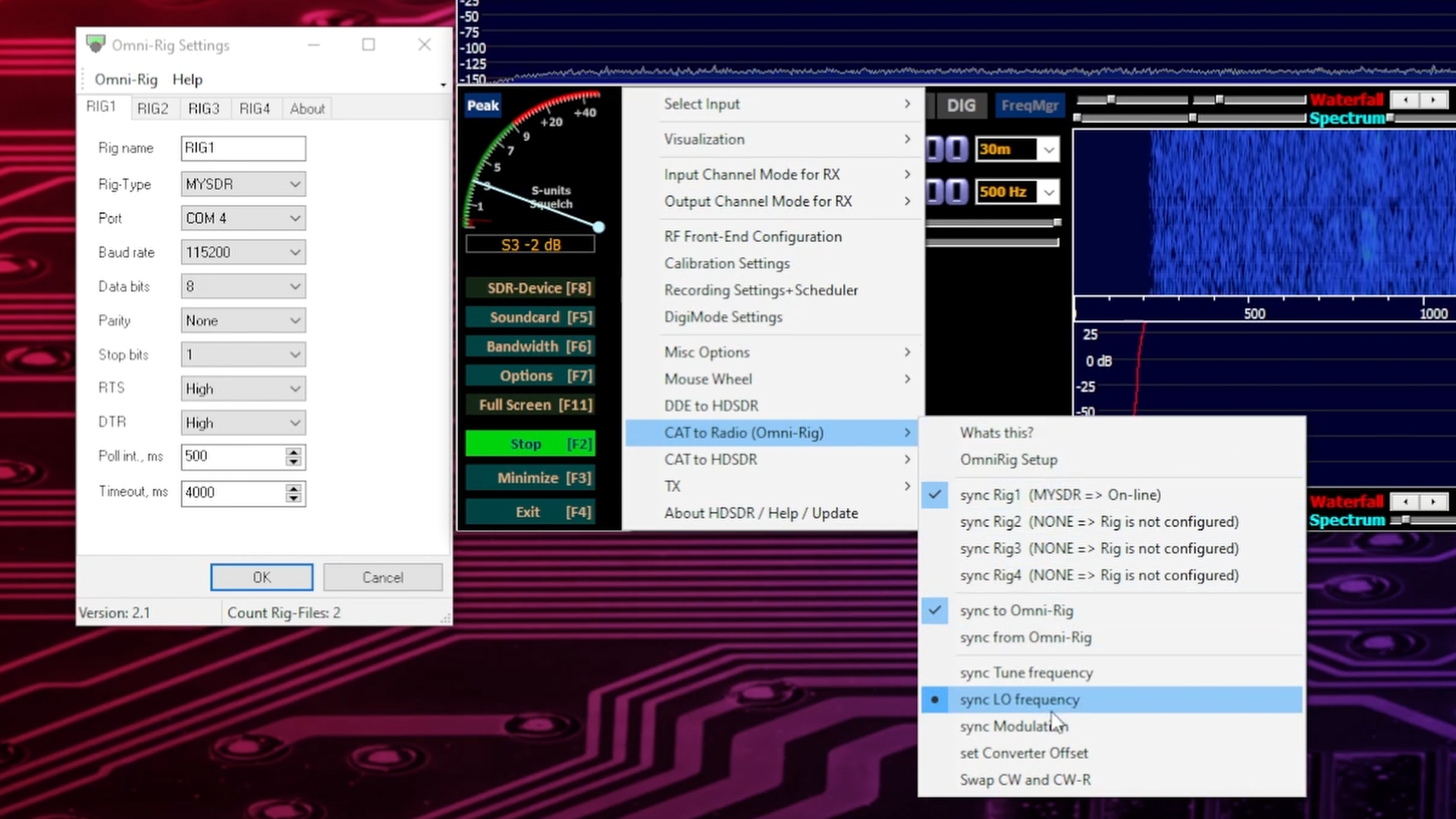
%APPDATA%\Afreet\Rigs - Start Omni-rig and set a custom rig name (i.e. RIG1), Rig-Type: 'MYRIG', your COM-Port and 115200 as baud rate
- Configure Omni-rig and HDSDR like shown in the picture below:
