A system for hikers to document and revisit their past hikes.
The timelapse program is started on power up by the service: /lib/systemd/system/capra-startup.service
The (on/off) button is controlled by the service: /lib/systemd/system/capra-listen-for-shutdown.service
Electronically, the Capra Collector consists of the following components (items with an asterisk are further elaborated on):
- Raspberry Pi Zero
- Adafruit Powerboost 1000
- [Custom PCB: Cam Multiplexer](#Cam Multiplexer) *
- Custom PCB: Buttonboard *
- 2 x 21700 LiPo Batteries *
- 3 x Raspberry Pi Camera V2's
In the image below, a systematic view of the respective components is given. Note that power and GND connections are typically not shown in this image.
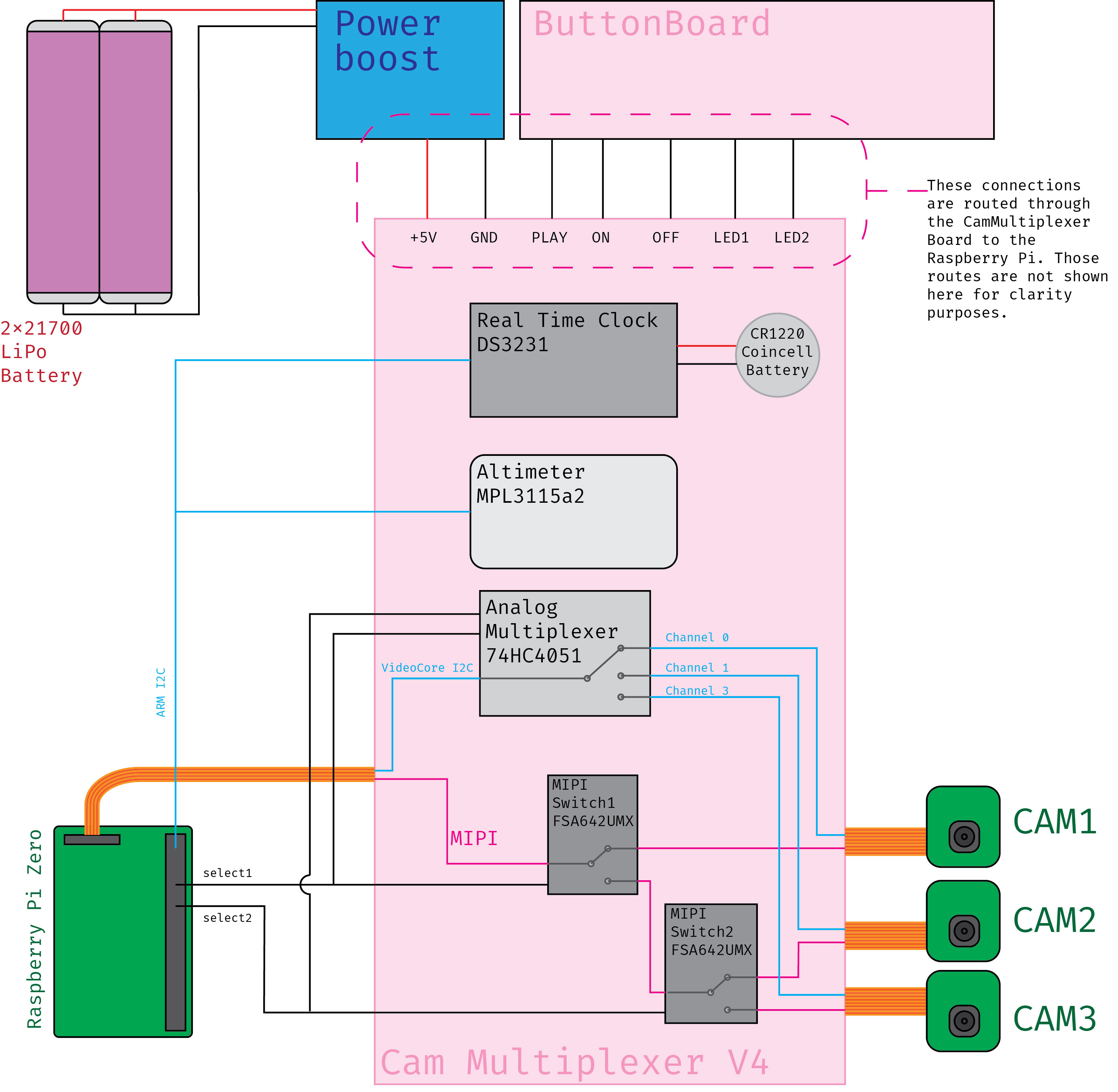
The Cam Muliplexer is a 30x70mm board directly placed on top of the RPi. While the RPi is typically only capable of connecting to a single camera the 'Cam Multiplexer V4' enables the RPi to switch between cameras and take pictures. The CamMultiplexer also incorporates a MPL3115A2 Altimeter that allows the RPi to sense its altitude.
Lastly, there is a DS3231 Real Time Clock (or RTC, for short) on the board that allows the RPi to keep its internal clock synchronised. In a typical scenario, a RPi sets its time on boot by querying an online time server. This, however, requires an internet connection; and while hiking you are likely not to have WiFi around all the time (that statement is not going to age well, I know). The DS3231 will continue to keep the time for the RPi, even when the RPi is off or runs out of juice. The RTC is connected to its own power source, a CR1220 Coincell battery. This battery will slowly drain, but slow enough to keep the Collectors' timekeeping accurate for several years!
The Cam Multiplexer requires limited soldering before being ready to use. This includes:
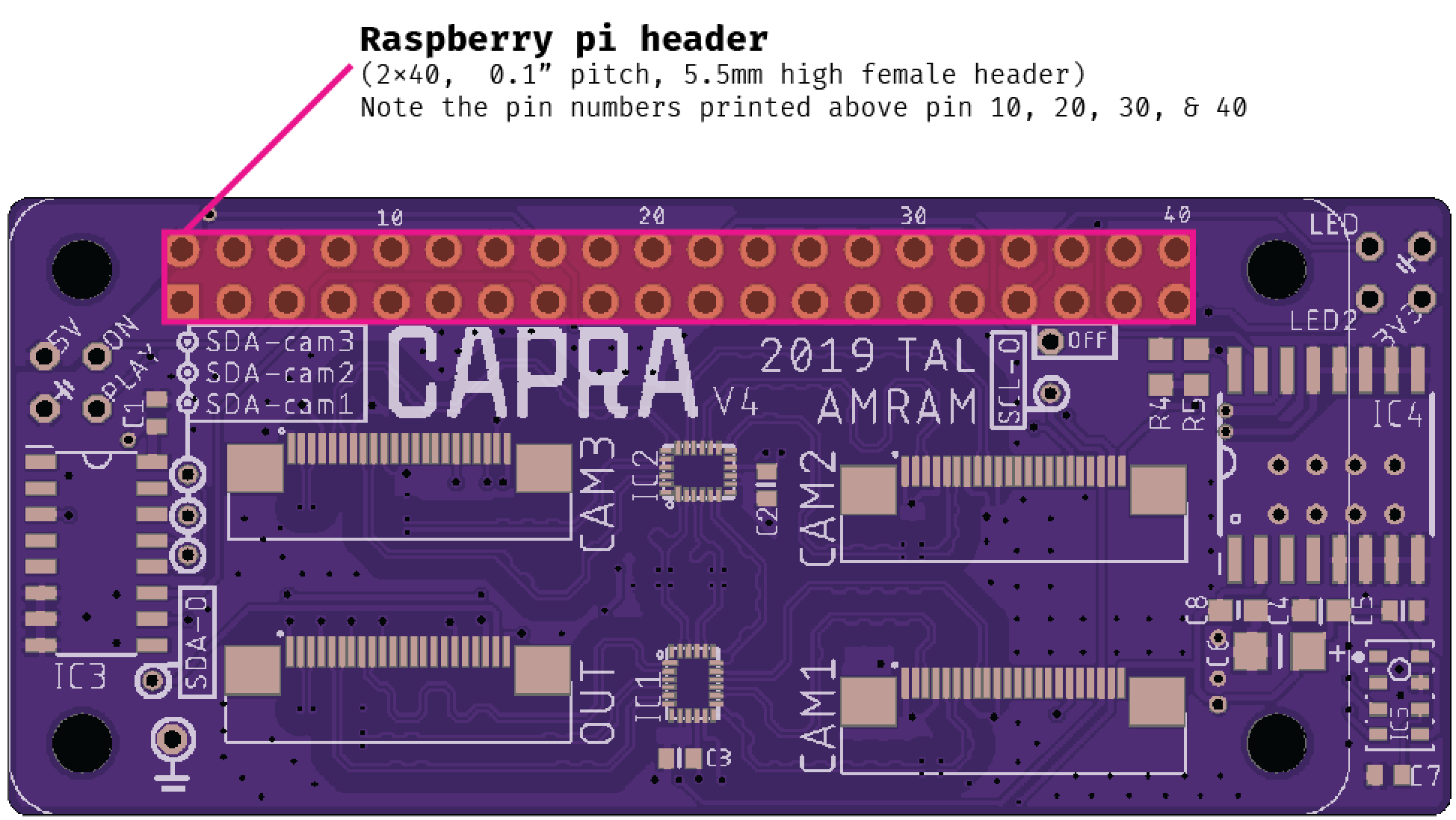
- soldering the 2*20 5.5mm tall female header
- applying a drop of solder to the GND connection of the coincell battery
- soldering the smd coincell battery connection
The flat cables (called 'FFC' - Flat Flexible Cable) contain all signals that travel between the cameras and the RPi. This article here explains what each single line in the FFC cable transmits. Shortly speaking, these signals can be categorised in two protocols:
| Protocol | Function | Connects | Through |
|---|---|---|---|
| I2C | RPI issue commands to the camera (e.g. set resolution, take picture) | VideoCore (GPU) of RPi ↔ Camera (Bidirectional) | Analog Multiplexer 74HC4051 (IC3) |
| CSI-2 | Contains all the data that comprise the image taken by the camera. | Camera → VideoCore (GPU) of RPi (Unidirectional) | FSA642UMX (IC1 & IC2) |
The table above echoes the systematic drawing in that it shows the signals between the RPi and the cameras being split up and switched via two different chips; this is due to the vastly different electronic requirements of those signals.
Note that the I2C meant in the context of the cameras is NOT easily directly programmable. The I2C bus that runs between the cameras and the RPi is called I2C-0. I2C-0 is controlled by the 'GPU' of the RPi (also referred to as the VideoCore). The 'regular' I2C bus (BCM 2 & BCM3) is an entirely separate I2C bus and is controlled by the ARM processor on the RPi. The latter bus talks to the Altimeter and the RTC and is called I2C-1.
I²C (or I2C, because that is easier to type) stands for 'Inter-Integrated-Circuit'. It is a data communication protocol that allows multiple devices to be connected to the same pins of a microcontroller, as shown in the image below. Never mind the weird terminology for this protocol.
In Capra's case, the Altimeter and RTC are both connected to BCM2 (SCL, short for 'Slave CLock') and BCM3 (SDA, short for 'Slave Data'); yet their functionality does not interfere with each other. This works through something called addressing. Each I2C device has a specific address; whenever the microcontoller wants to 'talk' to any of the devices, it first sends out an 'address': string of 1's and 0's over its data line (SDA). This address will correspond with one of the I2C devices: when this device 'hears' its address over the data line, it will start to listen for any commands the microcontroller might send next. The other I2C devices connected to that same dataline will hear the same address, but as the address doesn't match their own, will remain inert. Compare this with a phone call; where you'd first dial a number (analogous to an address) and then start talking to one specific, intended person (analogous to 'whatever commands the microcontroller sends next'). Using I2C is different per device. Typically, you can find documentation of how to address the device and what kinds of commands you can send to it in its datasheet. For the altimeter on Capra for example, its datasheet will tell you how to address it. However, the process of writing this kind of code is tedious. If you can, find an existing breakout board from Sparkfun or Adafruit with a component that fulfills your intended functionality. You can then integrate that circuit into your own (Sparkfun and Adafruit open-source their designs!!) and use their code to interface with the chip. Do attribute the author of the code you're importing in the header of your code and link to the respective originating GitHub repo!!
This PCB is placed towards the lower end of the Capra enclosure; and is fixed against the back piece. A 7-cable ribbon connects the buttonboard with the Cam Multiplexer. The following components are on the buttonboard:
- On Button
- Off Button
- Pause button
- 2-colour indicator LED
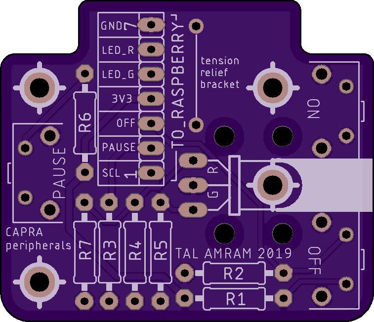
The Buttonboard has a row of connections labelled 'To_Raspberry'. This is where the 7-cable ribbon connects to the button board. These connections have individual names and should be routed as follows (BCM and BOARD numbers are shown for programming purposes):
| ButtonBoard | ↔ | Cam Multiplexer | BCM | BOARD |
|---|---|---|---|---|
| GND | ↔ | GND (⏚ symbol) | n/a | n/a |
| LED_R | ↔ | LED | 13 | 33 |
| LED_G | ↔ | LED2 | 26 | 37 |
| 3V3 | ↔ | 3V3 | n/a | n/a |
| OFF | ↔ | OFF | 25 | 22 |
| PAUSE | ↔ | PLAY | 17 | 11 |
| SCL | ↔ | ON | 3 | 5 |
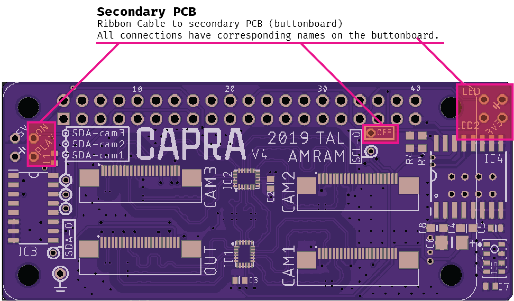
These connections can be found here on the Cam Multiplexer board, (Note that the 'OFF' connection is at an unexpected spot):
The v1 button board has some faulty connections in its manufactured state. In order to use the board, one needs to cut the following traces and apply these jumper wires:
Capra uses two 21700 LiPo batteries. More specifically, the batteries used are the Samsung 40T batteries. This specific battery type was chosen because two such batteries placed in parallel fit the shape of Capra perfectly and because the 40T model packs an impressive 4000 mAh capacity per unit. In the Collector, I've placed two such batteries in parallel to create a battery pack of 8000mAh @ 3.7V. The name 21700 refers to the diameter (21mm) and the height (70mm) of the battery - this is a common naming convention with cylindrical LiPo batteries.
Fun Fact: 21700 batteries were initially developed for electric vehicles. However, their main use nowadays is to power e-cigarettes. Hence, you will find them readily for sale at vape shops.
At an average draw of approximately 800mA @ 5V by the Capra system, the two batteries are able to power the system for an approximate 7,5 hours.

LiPo batteries do require a specific circuit to regulate their charging. For Capra, I chose the Adafruit PowerBoost 1000. This module 'boosts' the nominal 3.7V of the LiPo battery to 5V @ 800mA required by the RPI and has a load-sharing circuit. The load sharing circuit is what makes it possible to connect the Collector to a 5V USB power source (e.g. 5V powerbank, 5V wall outlet, etc.). Connecting such a power source will have the Collector run on that power AND charge the batteries while connected.
!! NEVER ATTEMPT TO CHARGE THESE BATTERIES WITHOUT AN APPROPRIATE CIRCUIT OR MODULE !!
!! NEVER EVER SOLDER WIRES DIRECTLY TO THE BATTERIES !!
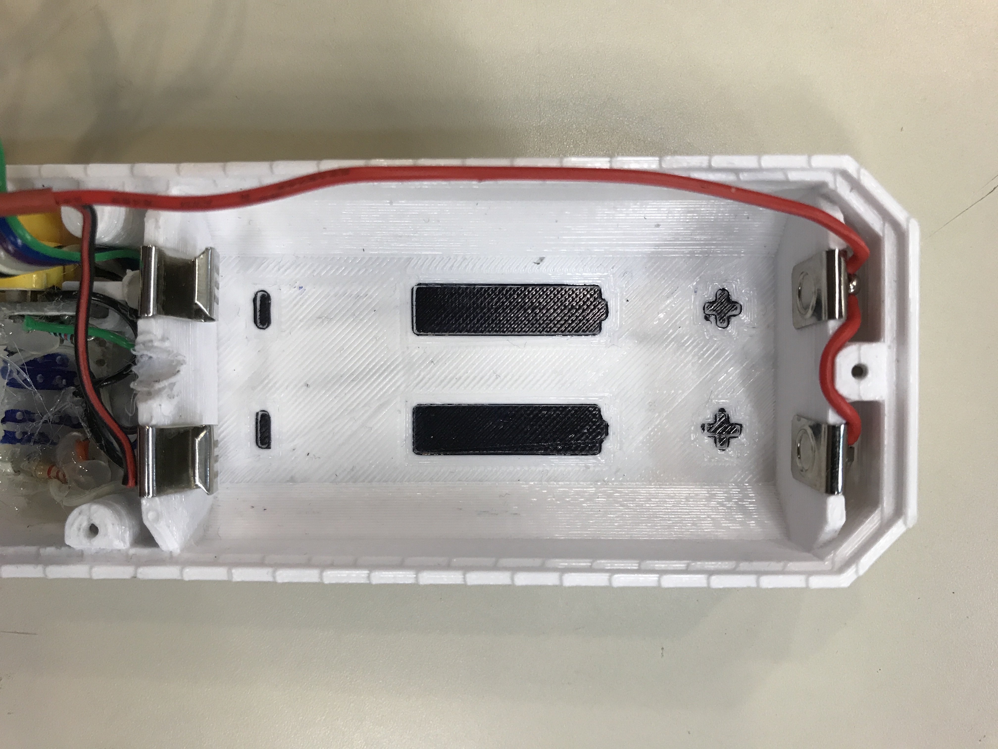
On the Collectors' back piece, there are recessed areas where the battery clips go. There are two types of battery clips used in the assembly. The one meant for the '+' terminal of the battery has a little circular marking on it (Product code 36-228-ND; the one meant for the '-' terminal of the battery has a texturised surface and is springy (Product code Keystone 36-209. These parts are shown below:
The '+' and '-' terminals should be connected in parallel to the JST-PH2 connector on the PowerBoost module. The output of the PowerBoost module should be connected to the following positions of the Cam Multiplexer:
| PowerBoost | ↔ | Cam Multiplexer |
|---|---|---|
| + | ↔ | 5V |
| - | ↔ | GND (⏚ symbol) |
Note the sides of the PH2 connector: the connection closest to the USB port on the Powerboost should be GND; the other should be +3.7V (power from battery pack).
21700 batteries have poorly indicated '+' and '-' terminals. This is extremely important to remain aware of while inserting them into the battery holders. If inserted the wrong way around, the batteries will immediately short circuit, resulting in melting wires at best and exploding batteries at worst. This will also irreparably damage the PowerBoost module. To mitigate such mistakes, mark the '-' side of new batteries with tape or permanent marker. The '+' terminal is recognisable by a round indentation. The '-' terminal is entirely flat.
The + terminal should be pointed upwards. The '-' terminal should be pointed down (towards the buttonboard). There is also a recessed marking on the back piece that shows the orientation of the batteries:
| LED | Location | Meaning |
|---|---|---|
| 💚 solid/blinking | Raspberry Pi | RPi is on |
| 💚 blinking | Button board | collector.py is PAUSED |
| 🔴 blinking | Button board | program is running |
| 🔵 solid | Powerbooster | Powerbooster has power |
| 💚 solid | Powerbooster | Batteries fully charged |
| 🔴 solid | Powerbooster | Batteries low |
| 🧡 solid | Powerbooster | Batteries charging |
New hikes are created from collector.py with the following line:
created = sql_controller.will_create_new_hike(NEW_HIKE_TIME, DIRECTORY)This function is defined in classes/sql_controller.py with
def will_create_new_hike(self, NEW_HIKE_TIME, DIRECTORY) -> bool:This class struction is based on a software design patter called Model View Controller. The idea is that a Controller class handles or controls the talking between two layers of logic. This way the UI (View) classes are never directly making database (Model) calls. Also, any additional logic checks, or in this case file system instructions, can be handled neatly outside of the UI class.
# Determine whether to create new hike or continue the last hike
    def will_create_new_hike(self, NEW_HIKE_TIME, DIRECTORY) -> bool:
        time_since_last_hike = self._get_time_since_last_hike()

        # Create a new hike; -1 indicates this is the first hike in db
        if time_since_last_hike > NEW_HIKE_TIME or time_since_last_hike == -1:
            print('Creating new hike:')
            self._create_new_hike()

            # Create folder in harddrive to save photos
            hike_num = self.get_last_hike_id()
            folder = 'hike{n}/'.format(n=hike_num)
            path = DIRECTORY + folder

            os.makedirs(path)
            self._set_hike_path(hike_num, path)

            return True
        else:
            print('Continuing last hike:')
            return False
Line 15 of the above function is what actually makes the call to create a new directory/folder.
There is a RealVNC Capra group for connecting to both the Collector and Explorer remotely. Login details can be found in the Dropbox.
Artefact that stores -and lets one browse- the archive of photos and data collected with the Capra Collector.
The Explorer consists of:
- Raspberry Pi 4
- Explorer Control PCB
- Samsung T5 500GB SSD
- Aaxa Pico Projector (P2-B; previously HD-Pico)
- Adafruit NeoPixel Strip
The Explorer Control PCB connects all control components to the Raspberry Pi. The control components on this PCB are:
| Name | Function | Pin | Component*** |
|---|---|---|---|
| S1 | NEXT | BCM 6 | Tactile |
| S2 | MODE* | ADC ch 2 | Tactile |
| S3 | PREV | BCM 12 | Tactile |
| S4 | PLAY/PAUSE | BCM 5 | Tactile |
| SL1 | MODE 1* | ADC ch 2 | Slider |
| SL1 | MODE 2* | ADC ch 1 | Slider |
| SL1 | MODE 3* | ADC ch 0 | Slider |
| SW3 | NAVIGATE | BCM A=23 B=24** | Rotary Encoder - rotation |
| SW3 | ALL/ONE | BCM 25 | Rotary Encoder - switch |
| ACCELEROMETER | ACC_X | ADC ch 7 | Sparkfun Module |
| ACCELEROMETER | ACC_Y | ADC ch 6 | Sparkfun Module |
| ACCELEROMETER | ACC_Z | ADC ch 5 | Sparkfun Module |
*The PCB offers some flexibility. Either S2 is installed on the board OR SL1 is installed. In the case of SL1, the three positions of the slider correspond to the three modes. In the case of S2 the user would toggle through the modes by repeatedly pressing the button. Hence the overlapping pin numbers between SL1 - MODE2 and S2.
**The component in question here is a rotary encoder. This component uses two pins (A & B) to determine either clockwise or counterclockwise rotation. Numbers in table are BCM numbers
***Component Numbers are:
| Component | Manufacturer Number |
|---|---|
| Tactile | 2-1825910-7 |
| Slider | MHS233K |
| Rotary Encoder | PEC11R-4215F-N0024 |
| Sparkfun Accelerometer | ADXL337 (breakout) |
DESIGN ERROR: The PCB has a design error regarding the MODE-related channels on the ADC (ch 0, 1, 2). They are routed as if they were connected to the RPi's GPIO and their functioning could rely on the RPi's internal pullup resistors. However, they are routed to the ADC; which does not have internal pullup resistors. This design error has two consequences:
- Channels 0, 1, 2 on the ADC are left floating when disconnected at the slider switch. These should be pulled low by separate 10kΩ resistors.
- The base of the switch is pulled low by a 10kΩ resistor (R1). Instead of pulling the base low, pull it high instead (i.e. connect R1 to the base of the switch and 3V3)
| Scripts to Run | Purpose |
|---|---|
sudo apt-get install exfat-fuse exfat-utils |
enables Raspberry Pi to read ExFat hard drives |
File transfer from the Collector to the Explorer is initiated when the Collector is physically placed over the Explorers controls. This is registered by the Explorer by a magnetometer that senses the magnetic field of a small magnet in the Collectors' housing. At this point, the Explorer starts two parallel processes: the file transfer is initiated and a transfer animation is started.
Needed library is included in the Makefile.
It may be useful to check out this guide for wiring up an MCP3008 that also has sample code for reading the basic values.
The code for getting values looks like the following:
import busio
import digitalio
import board
import adafruit_mcp3xxx.mcp3008 as MCP
from adafruit_mcp3xxx.analog_in import AnalogIn

spi = busio.SPI(clock=board.SCK, MISO=board.MISO, MOSI=board.MOSI)
cs = digitalio.DigitalInOut(board.D8)
mcp = MCP.MCP3008(spi, cs)
*Note that SCK, MISO, MOSI are all SPI (Serial Peripheral Interface) pins.
*Note that board.D8 refers to RPi Pin 24 / BCM 8. Accordingly, BCM 25 = board.D25 and BCM 5 = board.D5.