This project is designed to allow you to connect an Arduino/ESP8266 device to your Honeywell (Ademco) security panel and "listen in" for key events. This project is an implemenation of reverse engineering the Ademco ECP keypad bus.
Using a MAX3232 Breakout MAX3232 Connect the data-out wire (yellow) to a max3232 (R1IN) and the output (R1OUT) to pin RX(GPIO13) on the ESP8266. Connect the data-in wire (green) to a max3232 (T1OUT) and the output (T1IN) to pin TX(GPIO01) on the ESP8266.
             RS232 - 3.3V Interface                  |   ESP8266
                                                     |
+---------+                   +------------+         |  +-----------+
|         | Yellow Wire (12V) |   MAX3232  |TTL(3.3V)|  |           |
| Ademco  |------------------>|R1IN   R1OUT|---------|->|RX(GPIO13) |
|Vista 20P|                   |            |         |  |           |
|  Panel  |<------------------|T1OUT   T1IN|<--------|--|TX(GPIO01) |
|         | Green Wire (12V)  |            |TTL(3.3V)|  |           |
|         |                   |            |         |  |           |
|         |                   |         GND|<--------|--|GND        |
|         |                   |            |         |  |           |
|         |                   |     3V-5.5V|<--------|--|3.3V       |
|         |                   +------------+         |  |           |
|         |------------------------------------------|->|Vin        |
|         | Red Wire (12 Volts)                      |  |           |
|         |                                          |  |           |
|         |------------------------------------------|->|GND        |
+---------+ Black Wire (Ground)                      |  +-----------+
#define DEVICE_ADDRESS 19

HardwareSerial *myPanelSerial = &Serial1;
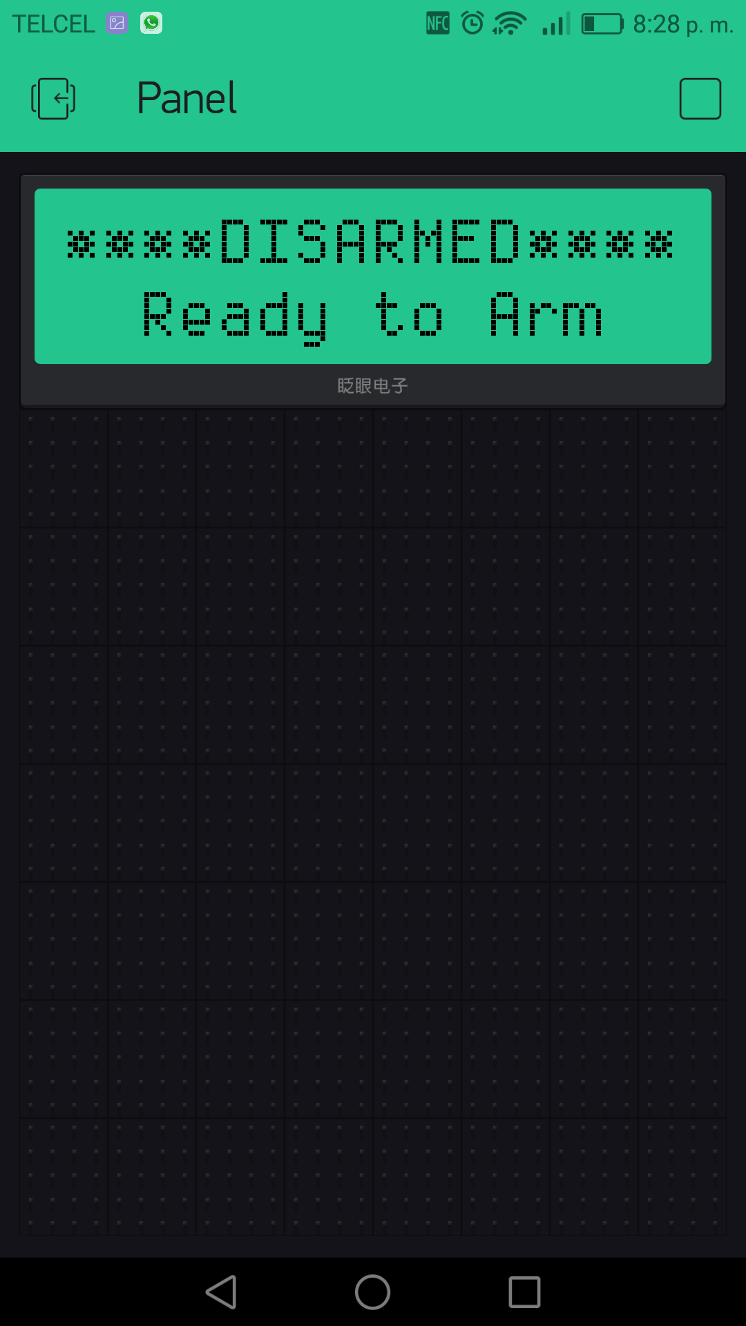
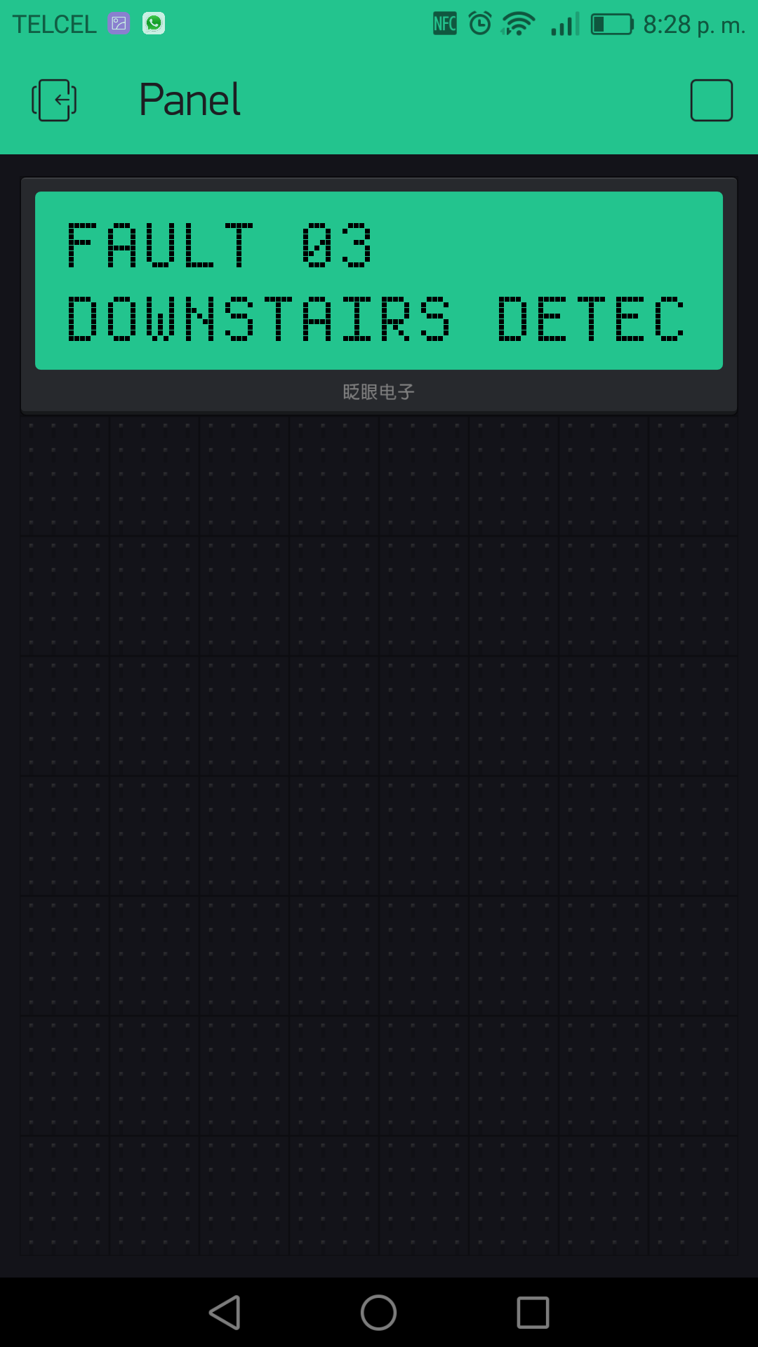
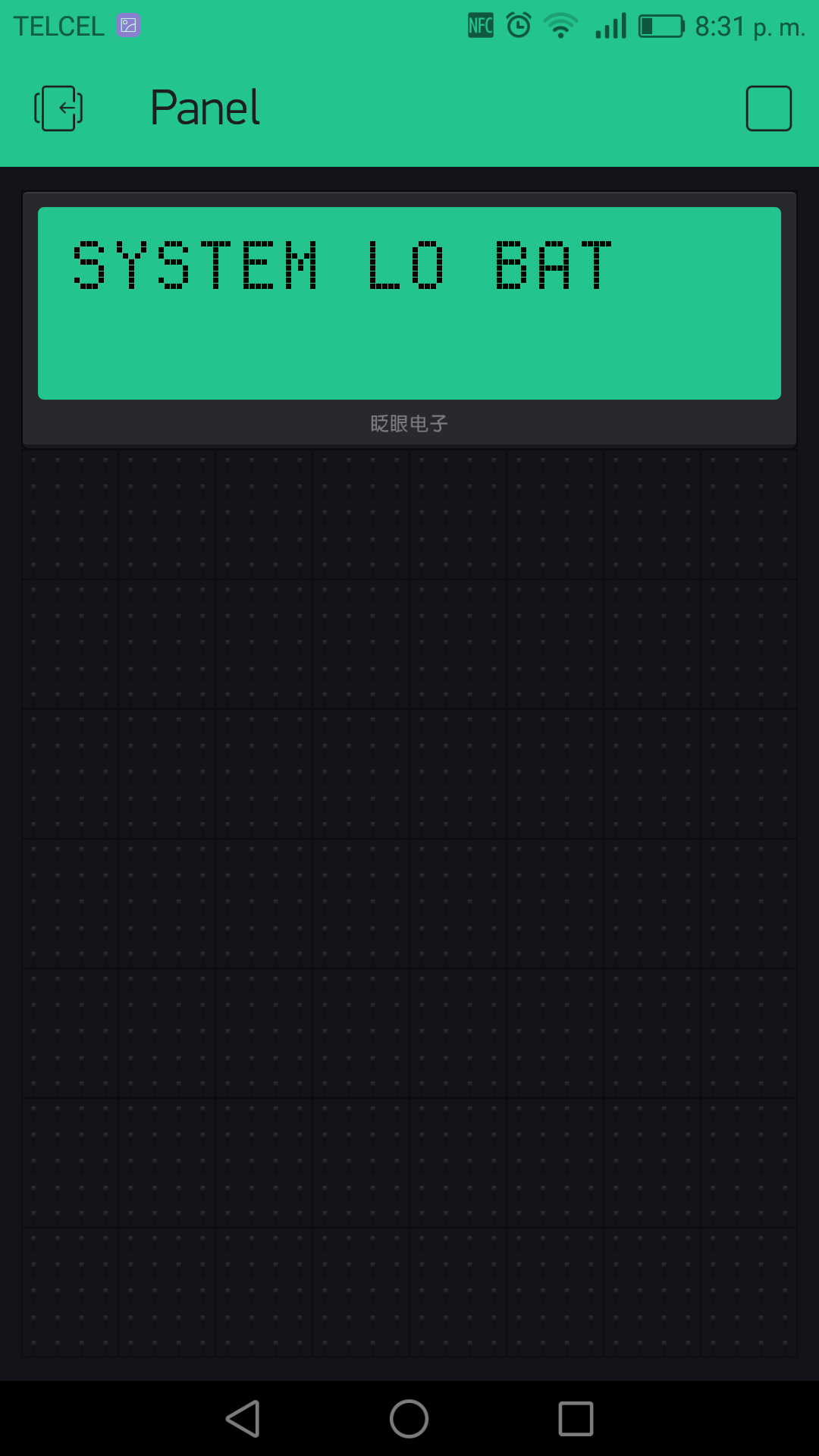
BUS_Reactor vista20p(&myPanelSerial, DEVICE_ADDRESS)This sketch publishes changes to a free blynk server you can download the native android aplication to see LCD on phone and use a terminal to see log and write to the panel. LCD should be on Virtual PIN1 and Terminal in Virtual PIN 0.
| Disarmed | Fault | System low Bat |
|---|---|---|
 |
 |
 |
Essentially, the data out wire uses 8-bit, even parity, 1 stop bit, inverted, NRZ +12 volt TTL signals. But, the data out wire also acts somewhat like a clock wire sometimes.
Regular messages are transmitted periodically and begin with either F7 or F2. F7 messages are fixed length, F2 are dynamic length. Both message types consist of a header and a body section. The second by of F2 messages indicate the remaining bytes for said message.
When behaving as a clock wire, the panel will pull the line low for an extended period of time (>10ms). When this happens, any device that has data to send should pusle a response. If the panel selects that device (in case there are multiple devices needing to send data) an F6 will be broadcast on the data out wire with the address of the device which should send data. F6 messages behave like normal serial data.
In order to avoid "open circuit" errors, every device periodically sends their device address to the panel. This happens after F7 messages, and as a response to input querying from the panel.
Pulsing doesn't exactly match up with serial data. Timing is handled by synchronizing to rising edges sent from the server. This can be faked by sending a 0xFF byte because the start bit will raise the line for a short time, and all the 1s will bring the line low (because the data signals are inverted). There doesn't seem to be any parity bits sent during this pusling phase.
When multiple devices ack, their pulses should coincide. The result is that the last bit is ANDed together.
Address 16 - 11111110 (inverted on the wire looks like 00000001) Address 21 - 11011111 (inverted on the wire looks like 00100000) Together on the wire they look like a single byte of 00100001 0x21
(high)---\___(10ms low)___/---\______/---\_______/---\_____  (Yellow data-out)

__________________________/\_________/\__________/\_/\_____  (0xFF, 0xFF, 0xEF) (Green data-in)
                         LSB                         MSB
                         1248 1248  1248 1248  1248 1248
Address - 16    FF,FF,FE 1111 1111  1111 1111  0111 1111
Address - 17    FF,FF,FD 1111 1111  1111 1111  1011 1111
Address - 18    FF,FF,FB 1111 1111  1111 1111  1101 1111
Address - 19    FF,FF,F7 1111 1111  1111 1111  1110 1111
Address - 20    FF,FF,EF 1111 1111  1111 1111  1111 0111
Address - 21    FF,FF,DF 1111 1111  1111 1111  1111 1011
Address - 22 FF,FF,BF 1111 1111 1111 1111 1111 1101This project uses some parts of Arduino IDE - specifically the SoftwareSerial library. So, whatever license that is under, this project is under (for the time being).
I could not have cracked the nut of Vista ECP protocol without knowing that it was possible by reading Miguel Sanchez's article in Circuit Cellar. Although he did not process signals sent from the panel, he figured out the baud rate, stop bit configuration, and the fact that the signal is inversed (0 is high, 1 is low).
Other projects that were invaluable to me are:
- Arduino SUMP analyzer firmware:
- Open Logic Sniffer (desktop):
- Original Code Mark Kimsal (homesecurity):