- tiny-m-build
- Electronics
- Software
- Raspberry Pi Setup
- Fluidd Pi
- Fluidd
- Mainsail OS
- Klipper onto SKR Mini E3 V2
- [Flashing MCU](#Flashing MCU)
- [Klipper Configuration](#Klipper Configuration)
- Wiring
Table of contents generated with markdown-toc
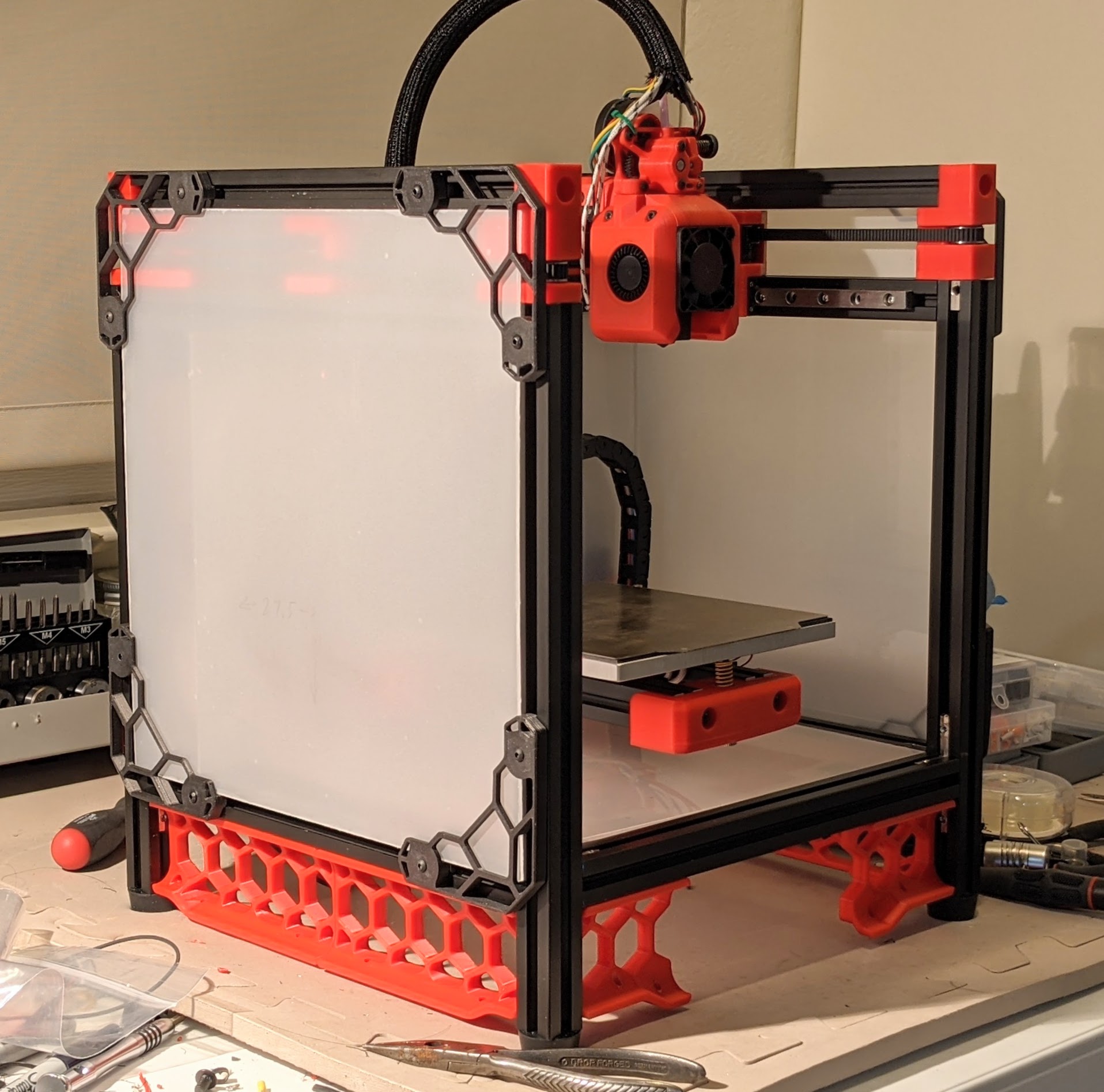
This is my particular spin on the Tiny-M build, a variant of the Voron V0 using Mitsumi 2020 Extrusions and Nema 17 motors. The Voron machines are home build high performance printers. With the V0 being the smallest of the series. The numbering scheme, V0, V1, V2 represent different machines, so don't get confused that's it's a revision.
My version of this is slightly different than the online CAD image. I want to used a BTT SKR mini E3 V2, a 24v heated bed (instead of 120v ac) and a direct drive sherpa mini instead of the regular boden drive.
see the cad image at https://github.com/gsl12/Tiny-M
I've finished the build. Will probably go with a simpler enclosure rather than the folding top hat, but need to design it still.

Many more build pictures at https://photos.app.goo.gl/qUpFSqQ5FszeDbXW6
The first things I'll link are the Voron V0 build and the Tiny-M repo. I'd like to use a small direct hot end instead of the standard Voron V0 Boden so that it will easily print flexable material. In addition, I really like the two position hinged TopHat by hartk1213
There is a very active Discord channel for VoronDesign. The users are really helpful and friendly which for a home build 3d printer is a huge win.
Voron V0 - https://vorondesign.com/voron0
Tiny-M https://github.com/gsl12/Tiny-M
Sherpa Mini-Extruder https://github.com/Annex-Engineering/Sherpa_Mini-Extruder
Hinged Top Hat - https://github.com/gsl12/Tiny-M/tree/master/STLs/usermods/2020_Hinged_TopHat_Print
Motion controller - BIGTREETECH SKR Mini E3 V2.0 New Upgrade Control Board 32Bit with TMC2209
Job control - Raspberry Pi Zero W, Pi 3 or 4?
T8x4 ptfe coated Lead Screw + POM - 215mm *Note: will have to cut to length as this isn't standard.
Many images so far from Xile on Voron group on discord
Want to use an external 24v supply and then all 24v on the Tiny-M. This means a 24v heated bed which is normally 120v ac. It removed all 120ac from the underside of the build making it a bit safer. Sourcing the bed heater is harder though as is the connection of the power to the chassis.
Got the DC power using the following.
External Mean Well 220 watt 24v DC power supply https://www.digikey.com/en/products/detail/GST220A24-R7B/1866-2085-ND/7703643?itemSeq=348860603
Power inlet to match - https://www.digikey.com/en/products/detail/KPJX-PM-4S/2092-KPJX-PM-4S-ND/9990081?itemSeq=348766398
Power switch - https://www.digikey.com/en/products/detail/RB141C1000-135/EG5684-ND/8540808?itemSeq=348859736
NOTE: The power switch burned it's light out at 24v, suggest adding a voltage drop resistor.
While I really like the idea of 24v of external power with a distribution via this nifty board, I didn't want to have to manufacture a 4 layer board just for my power input, so I decided to go with the simpler solution above.... https://github.com/JNP-1/VoronUsers/tree/master/printer_mods/JNP/PCBs/Supply_PCB
Along with an external power brick with a microfit connection
https://www.digikey.com/en/products/detail/VES220PS24/1470-VES220PS24-ND/10440644?itemSeq=347136397
Use the following when determining how much power a guage of wire can handle https://www.engineeringtoolbox.com/wire-gauges-d_419.html
https://docs.google.com/spreadsheets/d/1UV62ADl2gtK5vL0fV1nwevR6O9Ppzs0MBe7jnsI-jo4/edit?usp=sharing
The build plate should be either ATP-5 or MIC6 Cast Aluminum 6" x 6" x 1/4" which is about 150mm x 150mm x 6mm onto which a magnetic layer is added, topped with a spring steel build plate.
The heater for the bed should be aprox 0.4 watts/cm^2. So 15cm x 15cm = 255cm^2 255 * 0.4 = 102 watts. Less power will heat slower, more might be ok, but don't go crazy. See the following for great info https://duet3d.dozuki.com/Wiki/Choosing_a_bed_heater
Many Nema 17 will fit into the space. https://duet3d.dozuki.com/Wiki/Choosing_and_connecting_stepper_motors
Depending on if you are drilling + tapping for your rails or using the 90 degree internal connectors (or possibly both!)
If you are drilling (and have a printer) you can make a guide: See the STL drill template for the holes: 10, 36 and 60
The bottom extrusions have 50mm of space to the bottom of the uprights. The back is 26mm on the side beams for a total of 26mm + 20mm total (from the back beam).
While I really like the way the hinged TopHat works, I think I'll go with taller side panels, a taller door panel and a fixed top. I haven't had to have access to the top since I built it. I will re-use the hinged top-hat basic sizes though as the connection into the rails via the M5 is solid.
The hinged top hat has two positions it can stay in. There is a 2020 TopHat for V0 that I've patterned the following on (was at https://github.com/gsl12/Tiny-M/tree/master/STLs/usermods/2020_Hinged_TopHat_Print)
The following measurements have not been verified in an actual build.
Verticals
Back 2 x 75 mm
Front 2 x 92 mm
Horizontal
Front 2 x 260 mm
Back 1 x 260 mm, 1 x 274 mm
Sides
Top Right/Left 2 x 260 mm
Bottom Right/Left 2 x 230 mm
Totals
2 x 75 mm
2 x 92 mm
2 x 230 mm
5 x 260 mm
1 x 274 mm
The BTT SRK mini E3 V2 (not the older models) is my choice for this build. In pariticular, it has a beefier Mosfet for driving the heater bed. It has many other fine updates too: 2 fan outputs. a proper ground return for drivers, and better thermistor circuitry (thanks Ocho).
Raspberry Pi 3/4, or Zero W. Any of these will work with Klipper software as it's got a fairly light overhead.
Display - FYSETC V2.1 Mini 12864 is what I have on hand. The wiring to the SRK mini E3 V2 is a bit weird. There is a board that plugs into the USB on the Pi that then easily connects to the two 10 pin connectors. Alternatives are possible here.
For the steppers, I chose all LDO motors which have a great reputation. The X/Y/Z are all 0.9 degree LDO 17HS19-2004S (which also deviates from the original Tiny-M BOM with 1.8 degree steppers).
Endstops - I am using some D2FC-F-7N that I had on hand from fixing a Logitech trackball mouse. (I have to ream out the mounting hole to fit M2).
I would like to try sensorless homing since the TMC2209 support this mode but have not gotten to this yet.
Additional, stealth chop makes the motors REALLY quiet, this would be pretty cool to also try.
Thinking of using Raspberry Pi 2 (or 3) with Fluidd and Klipper on BTT SKR Mini E3 V2 By using Fluidd Pi, install should be relatively easy.
The Raspberry Pi runs Klipper which spits out G-code for the Mini E3 to drive the stepper motors. The Raspberry Pi connects to the Mini E3 via the USB cable that comes with the Mini E3.
While I'm using a Pi 4, I'll be trying out FluiddPi, so this is just to get the rest of you going should you want to do it all yourself and download an Image. I strongly suggest you go the FluiddPi route....
Download the latest Raspberry Pi OS Lite image, mine was a 5.4 from Dec 2, 2020 and use Etcher or something similar to burn an SD card with the image. I happened to use a 32G card on a Raspberry Pi 4, but smaller cards and slower Pi will also work.
https://www.raspberrypi.org/software/operating-systems/
https://github.com/vladbabii/raspberry_os_buster_read_only_fs
FluiddPi - A Pi image with Klipper, Moonraker, Fluidd and Web Camera support pre-installed. - cadriel/FluiddPI https://github.com/cadriel/FluiddPI
- Download the latest FluiddPi Image, I used v1.2.2 at https://github.com/cadriel/FluiddPI/releases/download/v1.2.2/fluiddpi-rpi-lite-v1.2.2.zip
- Flash your SD card with the image (fluiddpi-rpi-lite-v1.2.2.zip in my case), I used BalenaEtcher for OSX.
- Connect the Pi to your monitor (funky adapter cable needed for HDMI on Pi 4) and keyboard, login: pi password: raspberry
- Run "sudo raspi-config" and walk through each menu item.
4a. I choose wireless options and connected to my home wireless, but you could also go wired via Ethernet.
4b. Give your Pi a hostname and probably set it to your timezone for ease of looking at your log files.
4c. Enable SSH so that you can remotely get into your Pi
4d. Update Pi with various patches
4e. exit 'raspi-config'
4f. update/upgrade the Linux system "sudo apt update" and "sudo apt upgrade" 4e. Reboot and prove all the stuff you just did works
Run "ifconfig" and determine your IP address. Note: You might want to get the MAC address and set a static IP address in your DCHPD configuration of your Wireless Router. Use SSH (on OSX/Linux) or PuTTY on Windows and remotely login to your Pi. The command will be similar to "ssh pi@192.168.1.164" but with your IP address.
In addition, if you browse on your network to http://192.168.1.164/fluidd#/configuration you can start configuration of your system
https://github.com/cadriel/fluidd/blob/develop/docs/README.md
https://github.com/raymondh2/MainsailOS/releases
How to install
https://www.youtube.com/watch?v=MK0-MDVJG94
How to configure mainsail
https://meteyou.github.io/mainsail/setup/
Connecting
https://discord.com/channels/460117602945990666/741806179247980695/768032201362767893
Web Camera for Mainsail https://lazarofilm.gitbook.io/3d-printing/setting-up-your-pi-camera-for-mainsail
Klipper code needs to run on the Pi and communicate with the MCU. Our MCU is the BTT SKR Mini E3 V2 and the following is how to set it up.
Note pin difference from earlier SKR mini boards. \
VoronDesign/Voron-0#51 for V2 vs V1.x difference
https://discord.com/channels/460117602945990666/696930677161197640/746051951447375983
https://github.com/VoronDesign/Voron-0/blob/master/VORON-0/Manuals/V0_Setup_Guide.pdf
Another example configuration of SKR Mini E3 V2 for klipper
https://github.com/KevinOConnor/klipper/blob/master/config/generic-bigtreetech-skr-mini-e3-v2.0.cfg
Copy the appropriate file from the configuration directory in this github to /home/pi/klipper_config/printer.cfg (or similar if you have it in a different place.
Example: OSX & Linux
$ scp configuration/printer.skr.mini.e3.v2.cfg pi@192.168.1.164:/home/pi/klipper_config/printer.cfgUse the following as a reference for configuration of Klipper for BTT SKR mini E3 V2

Then, on the Pi move to the klipper directory
$ cd klipper
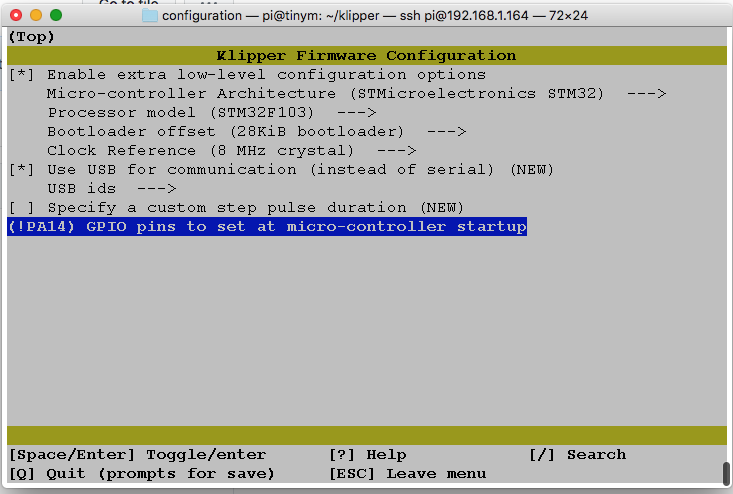
$ make menuconfig
.
.
.
~/klipper $ cp out/klipper.bin ~/firmware.bin- Now remove the SD card from the SKR mini and copy this file onto it.
- Place card into MCU and apply 24v power, wait 1 minute and turn power off
- Remove card, and look at the contents and the "firmware.bin" file should have been renamed to "FIRMWARE.CUR"
- The MCU is now up to date and ready to work with Klipper
First power on the Pi and then the SKR Mini E3 V2 then log into the Pi and run a couple of commands
Issue the following command, then plug in the USB cable and you should see something like:
$ dmesg -w -t
...
cdc_acm 1-1.1:1.0: ttyACM0: USB ACM device
usb 1-1.1: USB disconnect, device number 5
usb 1-1.1: new full-speed USB device number 6 using xhci_hcd
usb 1-1.1: New USB device found, idVendor=1d50, idProduct=614e, bcdDevice= 1.00
usb 1-1.1: New USB device strings: Mfr=1, Product=2, SerialNumber=3
usb 1-1.1: Product: stm32f103xe
usb 1-1.1: Manufacturer: Klipper
usb 1-1.1: SerialNumber: 35FFDB054246313020791057
cdc_acm 1-1.1:1.0: ttyACM0: USB ACM device
Klipper should now be able to use a mapping that contains the serial number, copy this info into the 'serial' line in the configuration file
$ ls /dev/serial/by-id/
usb-Klipper_stm32f103xe_35FFDB054246313020791057-if00
Edit the klipper_config file
$ vi klipper_config/printer.cfg So now the cfg should contain your printer
$ grep serial klipper_config/printer.cfg
serial: /dev/serial/by-id/usb-Klipper_stm32f103xe_35FFDB054246313020791057-if00
If you don't see the /dev/by/serial section, double check your USB cable and ensure each board is correctly powered on.
For Klipper to run without throwing errors, it expects to see valid information from it's configured thermistors. So wire up the hotend thermistor to PA0.
If you don't have a heated bed (or it's not installed yet), then comment out the "[heater_bed]" section as well as the last 5 lines of the printer.cfg file
Remove the last 5 lines in printer.cfg file
## [heater_bed]
## control = pid
## pid_kp = 37.593
## pid_ki = 1.139
#*# pid_kd = 310.142\
Follow the V0 guide for steppers, limit switches, hot end, bed heater, bed thermal cutoff switch, etc.
The best set of info for this is the V0 assembly manual which is oddly not on the Voron main site, but only in the GitHub location https://github.com/VoronDesign/Voron-0/blob/master/VORON-0/Manuals/V0_Setup_Guide.pdf
The Wago wire connectors can make your life a bit easier too.
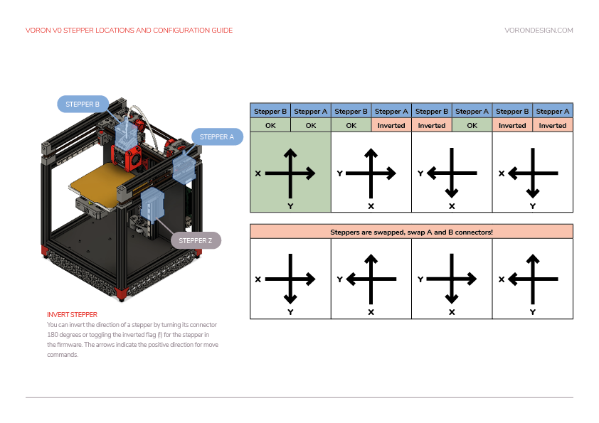
Back Left Motor B Connects to X
Back Right Motor A Connects to Y
Direction of X is inverted as well as Y in the configuration file (at least for my wiring).
Watch the video and note that if you use the 90 degree internal corners, you'll only need two holes in the build plate. You'll still have a bunch of tapping though so worth watching.
https://www.youtube.com/watch?v=2dvbn0rWA60&feature=youtu.be
Carefully review the Tiny-M CAD via OnShape
https://github.com/gsl12/Tiny-M
While I found OnShape slow to load on my aging 2011 iMac, it did pretty darn good once loaded.
I believe (but have not verified) that assembly of the tiny-m should be very similar to the V0 rails and build plate, so watch the following video:
https://youtu.be/Il6koDFPf7w
Build Plate - Wago 221 connectors make for very nice connections on the printer. They are not rated for the temperature at the bed, but unless you are running a very hot enclosed build, they should be OK a distance away. I used a couple of these holders mounted to the rails under the build plate. https://www.thingiverse.com/thing:4579456 The Wago 221 snap into place very firmly.
From Anin at https://discord.com/channels/641407187004030997/705183604535459871/785714455178248192
Coffee's video shows the correct assembly order for a K series printer where the lower two screws thread into the toolhead. For a standalone sherpa it might be easier to assemble things in this order:\
- Install all inserts (including 2 in the rear housing) and bearings, clean up the filament path with a 2mm drill bit\
- Sand/grind shaft (use the printed tool if necessary)\
- Insert the 50t gear/shaft assy into the bearing\
- Stack the core housing on top of the rear housing and install the lower two screws\
- Install the driven BMG filament gear, add a 5x7x0.5mm waher on top of the gear. Loctite the grub screw\
- Build and install the idler arm assembly\
- Install the front housing\
- Make sure everything runs freely\
- Install the motor and adjust gear meshing until there is only a tiny bit of backlash\
- Install the tensioner screw assembly
Note also that the tensioner screw insert can be up to 6mm long
The video reference.
https://youtu.be/3WogD5IUwAM
https://www.youtube.com/watch?v=3WogD5IUwAM&t=6s
Images of Dragon for Sherpa Mini
https://github.com/Annex-Engineering/Sherpa_Mini-Extruder/tree/master/Toolheads/Xile_Tiny_M/Dragon%20Toolhead/Images
Wiring: With the LDO pancake motor I did the wiring as follows: Blue-Yellow-Green-Red
**NOTE: There is a small 37mm (or so) boden tube between the Sherpa Mini and the Extruder. On the end that goes into the Sherpa Mini, enlarge the end with a drill bit so that filament feeds do not get stuck. **
