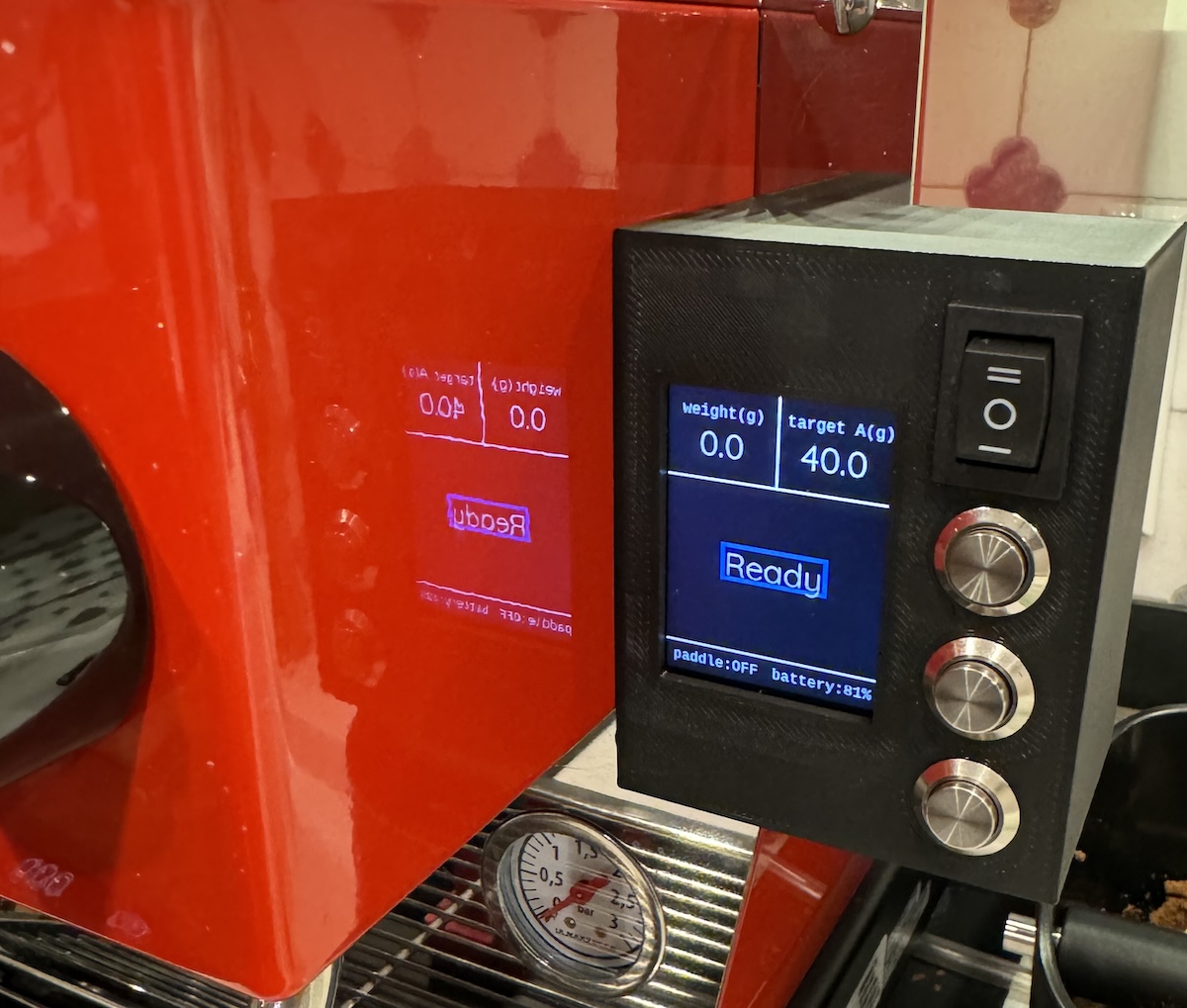
Apollo helps land espresso on your Lunar scale. This project adds brew-by-weight and a small controller for La Marzocco Micra with Acaia Lunar. It may also work with other Acaia Bluetooth scales like Pyxis.
This project is more about scale integration than Micra integration. It cannot do flow profiling or other advanced control over the Micra, it is simply collecting data from the scale and acting as a proxy for the paddle switch.
This is a hobby project, as such there is no support. It is sort of a hack/proof of concept being beaten into shape. Contributions are welcome, though this is very much designed to work according to my needs, for customization I'd suggest forking and making it your own.
Note that where external links are provided, they may not age well.
- A Raspberry Pi Zero 2 W w/soldered header
- 5v relay w/3.3v compatible logic control
- 5v 2a power supply
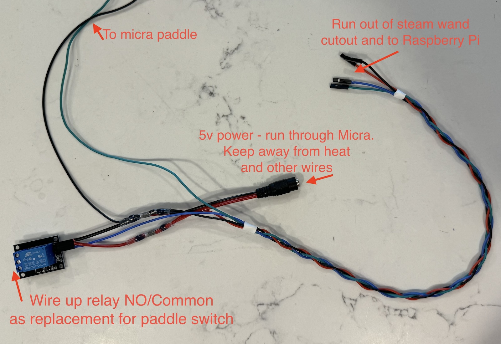
- 2.1mm barrel jack connector/wiring harness
- pushbutton switch x 2
- toggle switch
- up/down rocker switch (or two pushbutton switches)
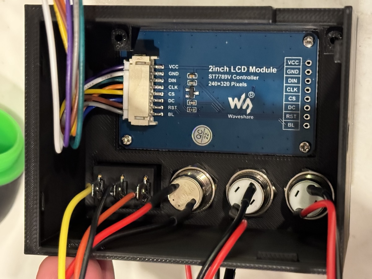
- 2" WaveShare 240x320 SPI display (or compatible)
- Screws - M2.0, M2.5 4mm length, or #3-24 in 1/4" length depending on your 3d printer tolerances
- Silicone 24AWG hook up wire
- Soldering tool and/or 2.54mm crimping set
- 3d printed enclosure, or self-provided alternative
A Raspberry Pi was selected to accommodate easy adoption of existing Python libraries without having to rework them to function on a microcontroller. Ultimately this is more flexible in terms of expanding functionality as well.
The software should support either the WaveShare 2.0" display
or the 2.4" display. The 2.4" display seems to have worse
viewing angles and is less sharp, and display_size needs to be updated in main(). For compatibility with the included enclosure, the 2" display should be used.
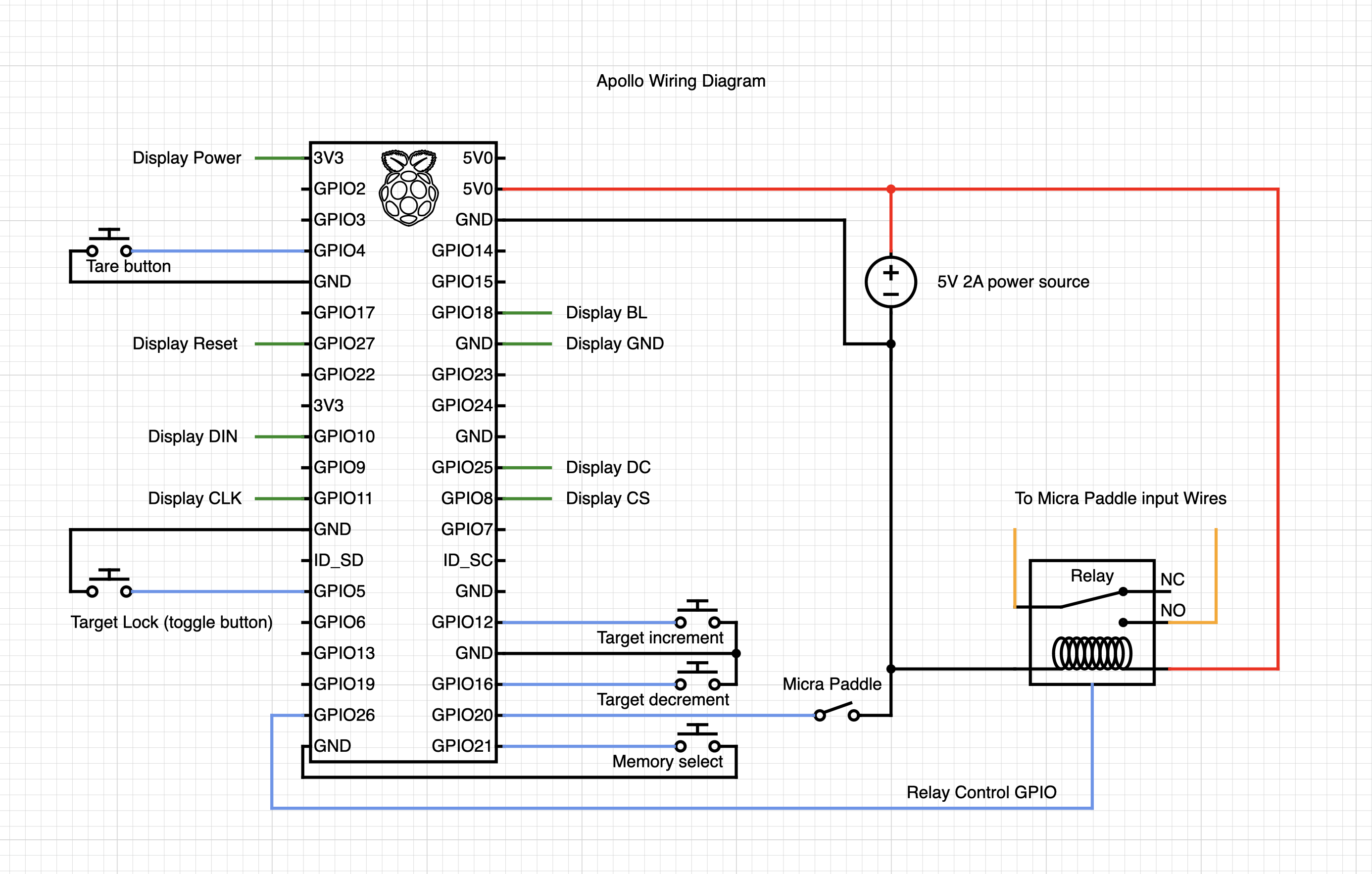
There isn't one specific relay to link to. Any 5v Arduino/Pi/ESP32 type relay should work. It will have common/NC/NO connections on the relay side and 5v/gnd/control pin on the controller side.
I use a momentary pushbutton switch for the tare and memory buttons, a toggle switch for the "target enable" button, and an up/down rocker switch for adjusting the target. The up/down rocker switch can be thought of as two momentary switches with a common ground - you can use two separate buttons as well.
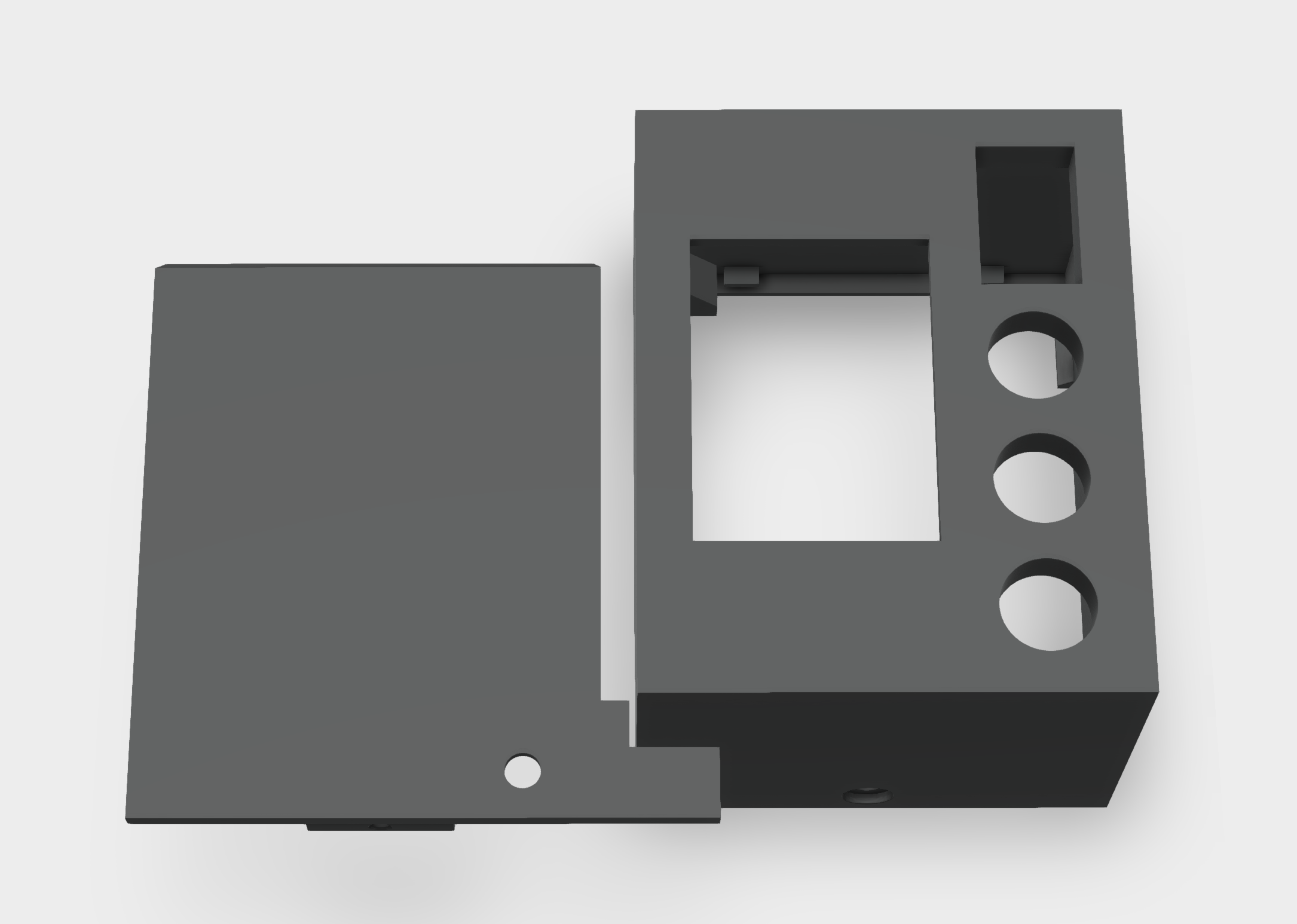
For compatibility with the included 3d printed enclosure, the buttons should be 12mm. The rocker switch should be rectangular and support 19mm x 13mm opening.
I found the quality of rocker switches a bit difficult, some had significant bounce leading to them being a bit tricky
to use. I bought several kinds and used what worked best. The model I ended up using was MXU1-2-123.
I bought a crimping tool in order to finish off the connections with standard Dupont 2.54mm connectors for easy wiring up to the Raspberry Pi header.
To simplify the wiring of power and controls between the Micra and the controller, I created a custom harness. This keeps the ground and power connections for the relay and switches in the Micra, with just 5v,ground and one wire per IO going back to the controller (4 pins total).
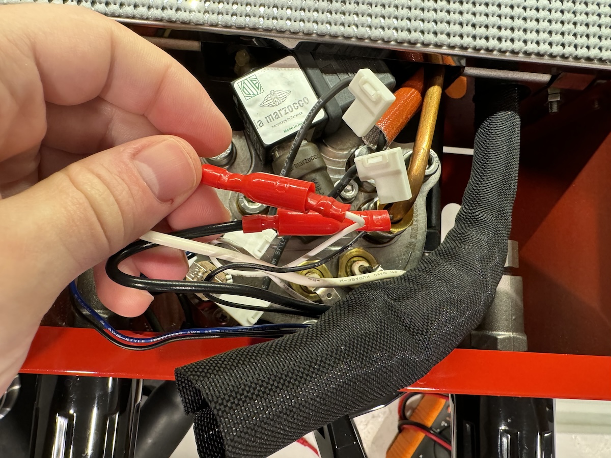
The Micra paddle is accessible by removing the top four screws above the group head. Here, you would find a wiring bundle containing black and white wires connecting to the paddle. These have bullet connectors which can be disconnected. You can insert the relay and Pi into this circuit to read the paddle state and control the Micra (or perhaps another device).
The enclosure STL file can be found here. It may need fine tuning, depending on the accuracy and tolerances of your printer.
Looking from the inside, the display mounts with four screws to the far side, along with the buttons.
The Raspberry Pi mounts above the display, using the standoffs on the right. There are only two mounts for the Pi.
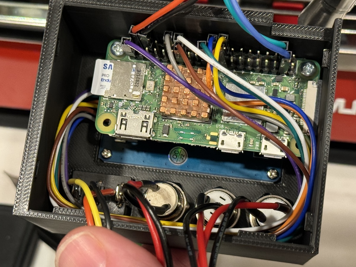
In all cases be careful not to over-tighten. Ensure everything is connected properly. Route the wiring for the paddle/power through the cutout and then up into the group area through the open hole by the steam wand.
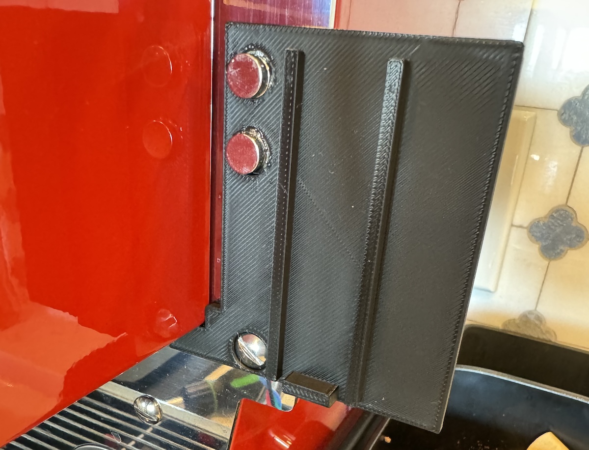
The backplate is designed to mount to the Micra on the right of the machine, using the large screw hole. Optional 8mm magnets can be placed to aid installation and help secure the top of the plate.
Then the enclosure hangs on the plate from the top clamshell-style. Once hung, a screw can be inserted to fasten the bottom of the enclosure to the plate.
It is assumed you have a Raspberry Pi Debian distribution already installed. As of this writing, Debian Bullseye is the recommended OS for the Pi Zero 2W. Other versions of Raspberry Pi may also work.
The SPI bus must be enabled to drive this display. Log into your Pi and run the following:
sudo raspi-config
Choose Interfacing Options -> SPI -> Yes to enable the SPI interface
Next, we want to release memory from the GPU for system use. Still in raspi-config, under Performance -> GPU Memory limit
set to 16M.
Finally, we want to disable the login UI. Under System Options -> Boot / Auto Login choose "Console"
sudo reboot
sudo apt install python3-pandas
sudo pip3 install bluepy
TODO: DEB package or install script
mkdir -p /opt/apollo/web
cp -r apollo.py lib /opt/apollo
chmod +x /opt/apollo/apollo.py
sudo cp service/apollo.service /etc/systemd/system
sudo cp service/apollo.env /etc/default/apollo
sudo systemctl daemon-reload
sudo systemctl enable --now apollo
By default, the software scans for any Lunar device in the vicinity and connects to it. There is no simple way to set a specific scale MAC address yet.
This controls the physical devices. It defines buttons, keeps state, and maintains scale connectivity.
Display class is responsible for defining how graphics are drawn, and updating the physical display as well as saving images of finished shots. It runs in a separate process so that display refreshes aren't blocked on anything else. To achieve this, current data is pushed onto a queue which is constantly read from - the queue is drained on each refresh and the latest data is displayed.
This was originally using matplotlib, which was CPU intensive and slow. Several other libraries were investigated, but they all had their own drawbacks (dependencies), optimization for webpage viewing, performance etc. In the end it was decided drawing the graph using simple lines was sufficient and performant.
The main loop is responsible for basic logic of setting up a Display and ControlManager, then orchestrating data collection and state updates.
A single frame can be generated using test_display.py for design changes to the display. Running pytest should be
sufficient to discover this test, run it, and open the resulting image on your workstation.
