
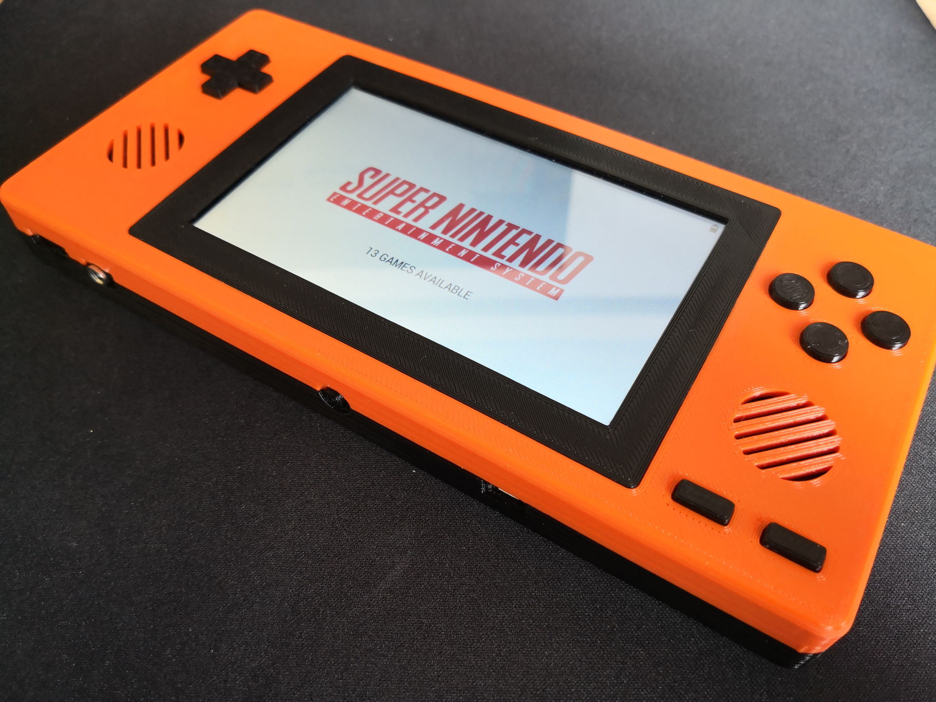
This repository contains everything to rebuild the simplyRetro Z5. The Z5 is my first attempt to build a custom emulation handheld from scratch. It runs a custom linux image for emulation to accomplish a fast boot time (10 seconds). But you are also able to use Retropie or Lakka for example (in both case you will loose the on screen battery indicator).
You can find a small video of it in action on Youtube.
This is my first self designed retro handheld. So please be aware that it could contain some flaws. Furthermore you should be able to handle a soldering iron and you have to understand basic circuits, if you want to rebuild the Z5. Please make sure that you understand the steps in the build section, before you decide to rebuild the handheld.
- Custom 3D printed shell
- Custom linux distribution for fast boot (from button press to emulationstation in 10 seconds)
- Single press power on and long press power off
- Battery Monitor icon and safe shutdown
- Stereo Speakers, Audio Jack and Volume Control
- 12 Buttons
- 5 inch display
- Raspberry Pi Zero powered
The Pi Zero and the 5 inch display are the reason for the naming Z5.
The model was designed in Fusion360. If you want to change the design, you can find the whole model here. The STLs are in the Thingiverse downloads and the Github repository. Furthermore there are exported STEP and Fusion360 Archive Files ready to download.
- 3D Printed Shell (STL folder for models)
- Elecrow 5 inch Display (If you want to use another display, make sure to adapt the shell)
- 12x Adafruit Softbuttons
- 1x 5mm Tactile Button for the Power Button
- 1x Powerboost 1000c
- 2x Speaker (or similar, just make sure they are 1W, 8Ohm and have a diameter of 3.4 cm)
- FPV HDMI Adapter (1xA1, 1xC1 and 1x5cm Cable)
- 1x MCP3008 ADC
- 1x Volume potentiometer (I took a GameBoy Color replacement part)
- 1x Jack Plug PJ-307
- 1x PAM8403 (Audio AMP)
- 1x 2500 mAh LiPo (like this one)
- Stripboard (if you want to use the same circuits as me for the battery monitoring and safe shutdown)
- Some M3x8mm screws (Mounts and Shell), M2.5x4mm screws (Electronics) and one M2.5x8mm screw (Top screw on the bottom shell, has to be smaller to get it fit)
- Resistors (6,8K, 10K, 100K)
- 1N4001 Diodes
- Velcro or double-faced adhesive tape to attach the PAM and circuits
- Wire :)
Thanks to AxelNobody! He created a alternative BOM with shop links for US citizens.
This chapter should help you to build the Z5. If you are missing something, or think it could be phrased better, you are free to create a Pull Request on Github. This way, together we can create a guide which is easy to understand! I will always keep the description on Thingiverse in sync to the Readme on Github.
Again, please be aware, that you should have basic soldering skills and you should be able to understand basic circuits. Make sure that you understand the steps in the build section, before you decide to rebuild the handheld.
I hope you got all your parts. Now it is time to assemble the Z5.
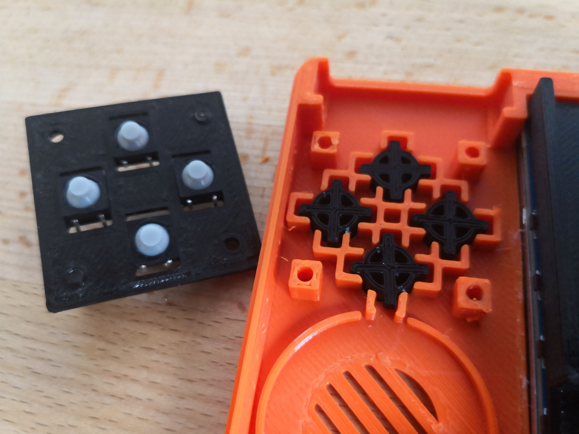
This part is easy. Take all your printed button mounts and insert the Adafruit SoftButtons into them. It should be a tight fit. Use a pliers, if necessary and bend one of the four button pins to prevent it to fell out from the mount. Insert the printed DPad and buttons into the upper shell and screw the populated button mounts on top. On the DPad please don't insert the upper right screw, and on the button mount the upper left screw, yet. These holes will be used to fasten the bottom half of the shell. The Shoulder Buttons and Shoulder Button Mounts will be inserted into the shell before it gets closed.
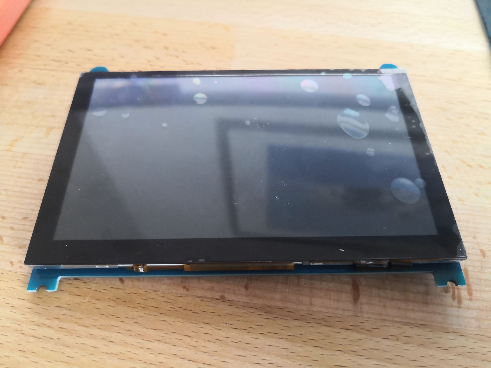
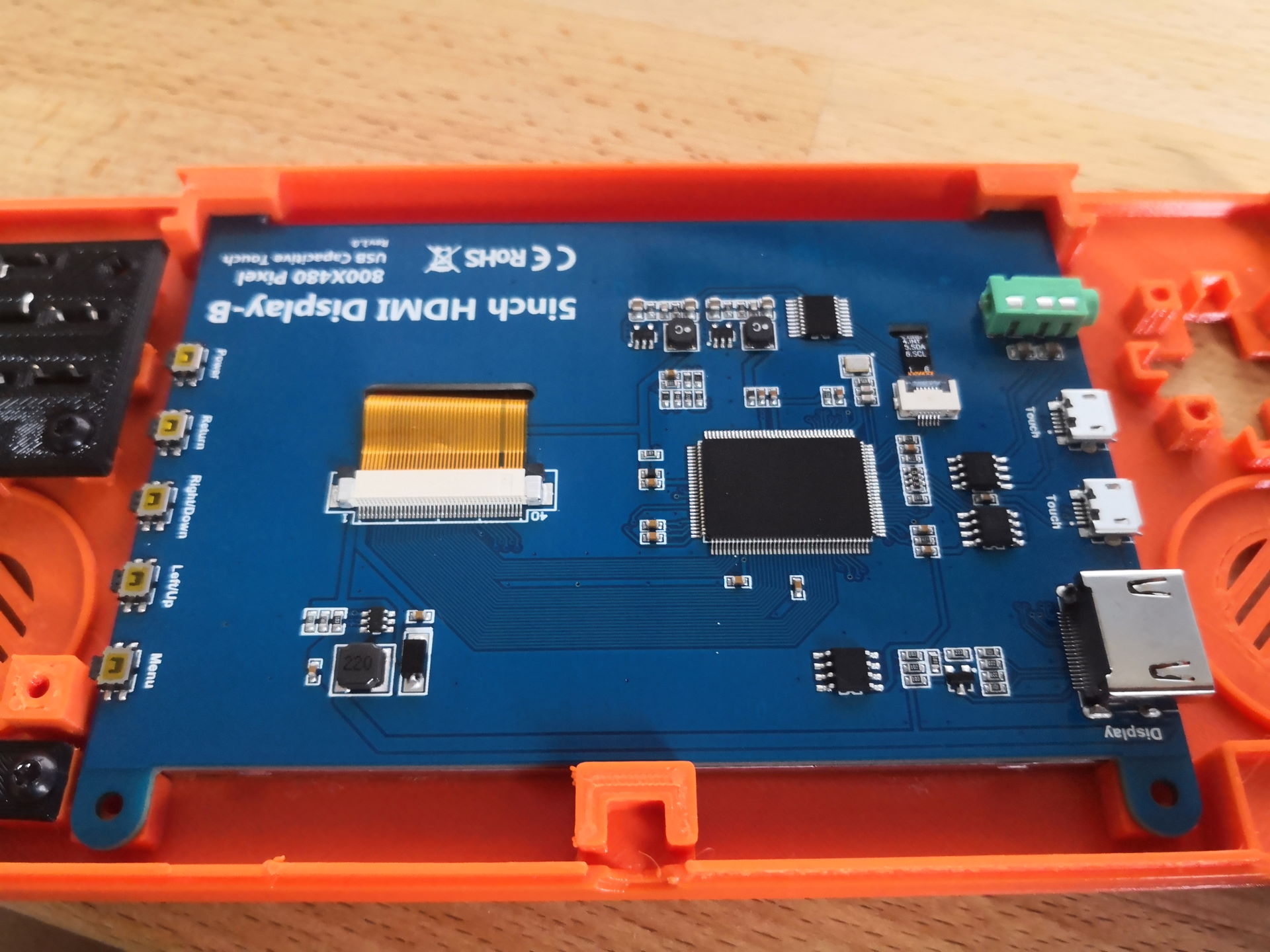
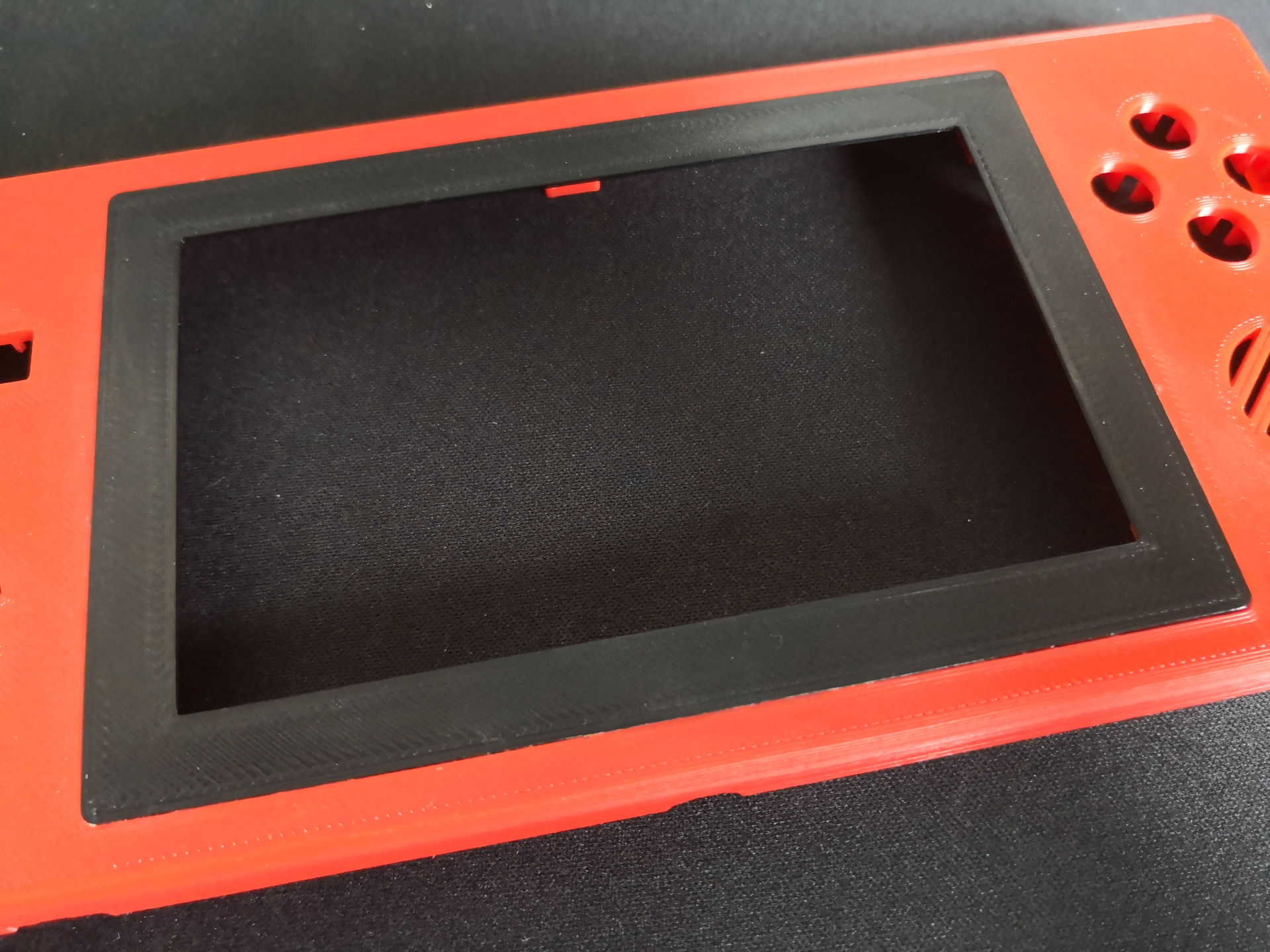
You have to install the display rotated by 180°. Otherwise we will get space problems with the HDMI connectors.
To fit the display into the shell, you have to cut off half of the bottom display mounts.
Please use the following two pictures as a reference.
Make sure you understand how to place the display, in the correct orientation, into the shell BEFORE you cut the mounts!
If your display is fitting into the top shell, you can remove it to glue the Display Frame to the upper shell. I used super glue. Give it enough time to dry before you proceed. Otherwise you will ruin your display!
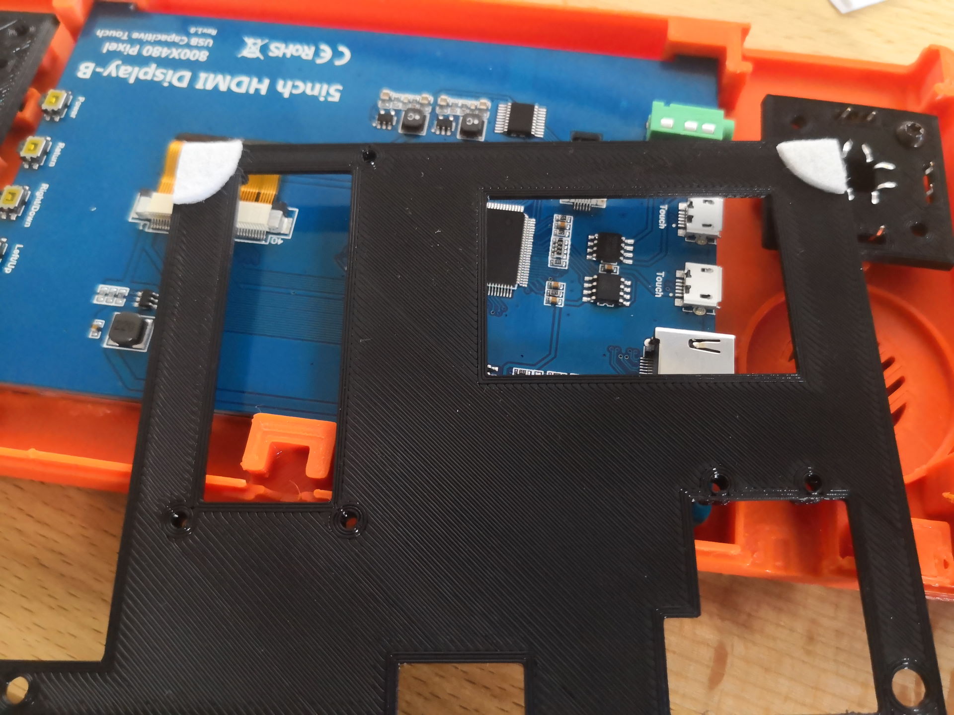
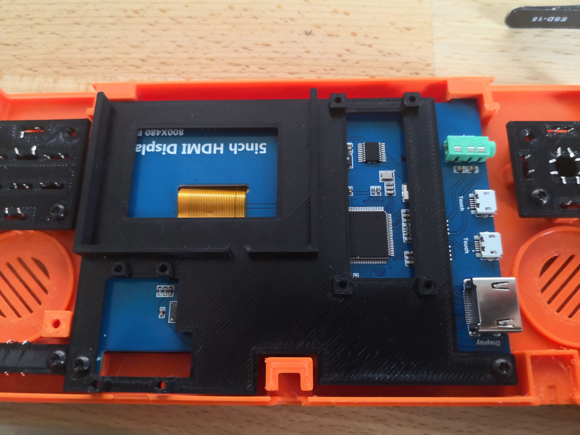
Now take the Electronic Mount and use for example a bit felt at the edge without mount holes (see the following picture). The felt just acts as a spacer between the display PCB and the Electronic Mount.
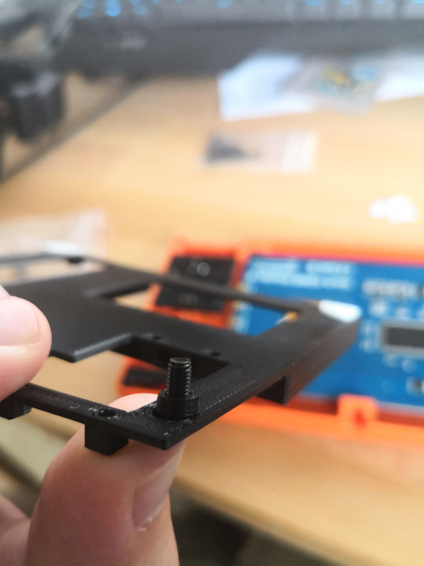
Now take the printed spacers and two M3x8mm screws and attach the mount to the display.
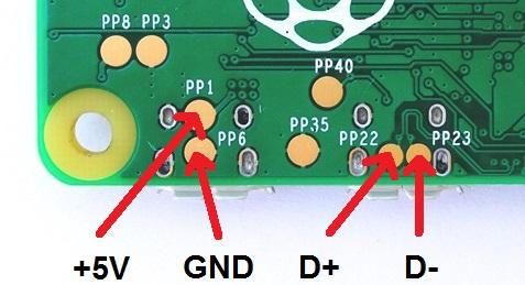
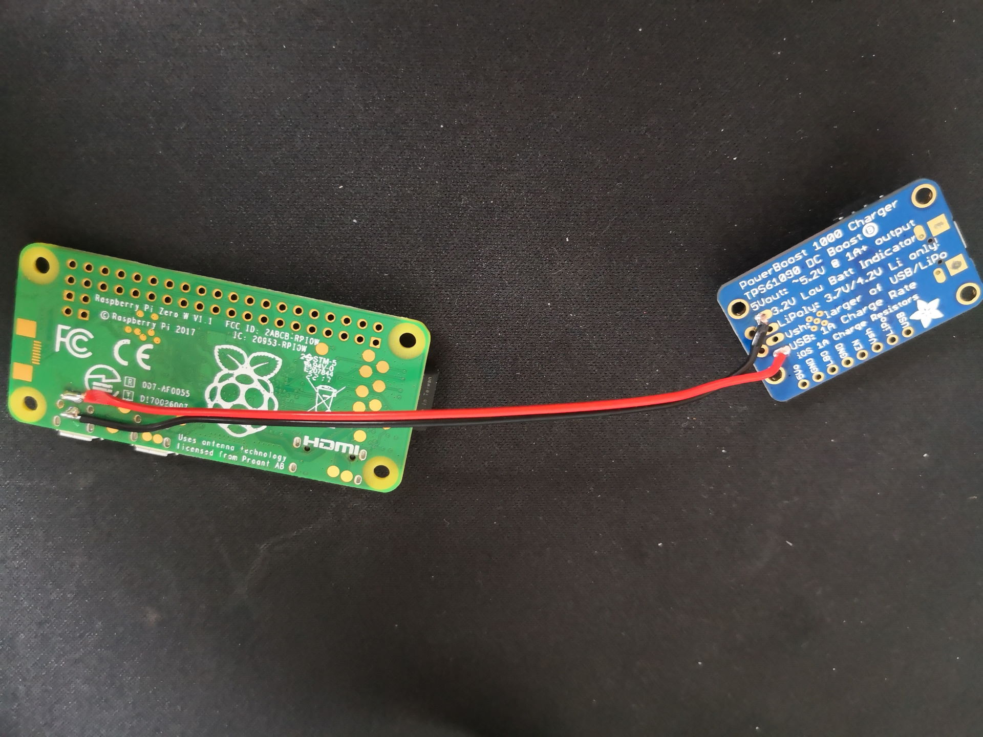
To power the Raspberry Pi Zero through the Powerboost 1000C, I soldered the PowerBoost to the USB test pads of the Raspberry Pi. I used the same pads to solder a short Micro USB cable (I used the one which came with the display) to power the display. Unfortunately I don't have a picture of this. Just search for the pinout of a micro USB adapter. You just need the Vcc and GND. If you are not sure which cable is which on your adapter, try to measure it with a multimeter.
Now you need to do your first little circuit for this project. The circuit to power the Pi on and off. You will need a piece of the Stripboard, the single tactile switch, three diodes, 1x100k and 2x10k resistors. Before you start soldering, you should do the needed cuts on the Stripboard.
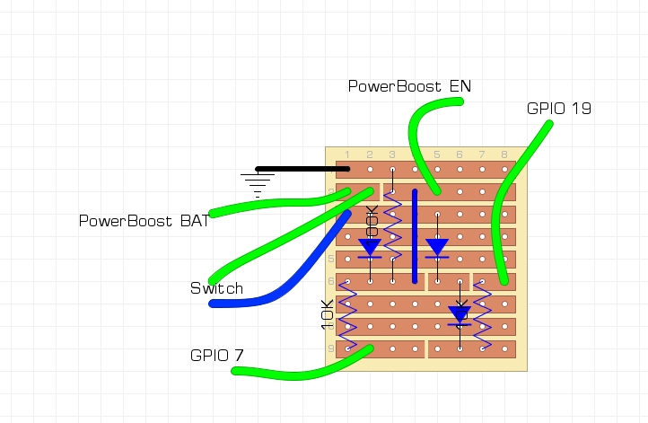
The circuit needs a bit of explanation. If the switch is not pressed, the Enable pin of the PowerBoost gets pulled to ground. This way the PowerBoost will be disabled when a battery is connected. As soon as the switch gets pressed, the Battery pin of the PowerBoost gets connected to the Enabled pin. This will enable the PowerBoost. Because we connected GPIO 7 of the Pi to the board the Enable pin will stay HIGH when the switch gets released and the board will stay powered on. You are able to use another pin than GPIO 7, but you have to make sure that you use a pin which is HIGH per default.
GPIO 19 is used as the power off pin. The simplyRetro Z5 custom distribution contains a small tool which listens to GPIO 19. If this pin gets HIGH and stays HIGH for a small amount of time a shutdown of the Pi gets initiated.
Because of the line
dtoverlay=gpio-poweroff,gpiopin=7,active_low=1
in the config.txt, GPIO 7 will go LOW, if the Pi is shutdown. This disables the PowerBoost again.
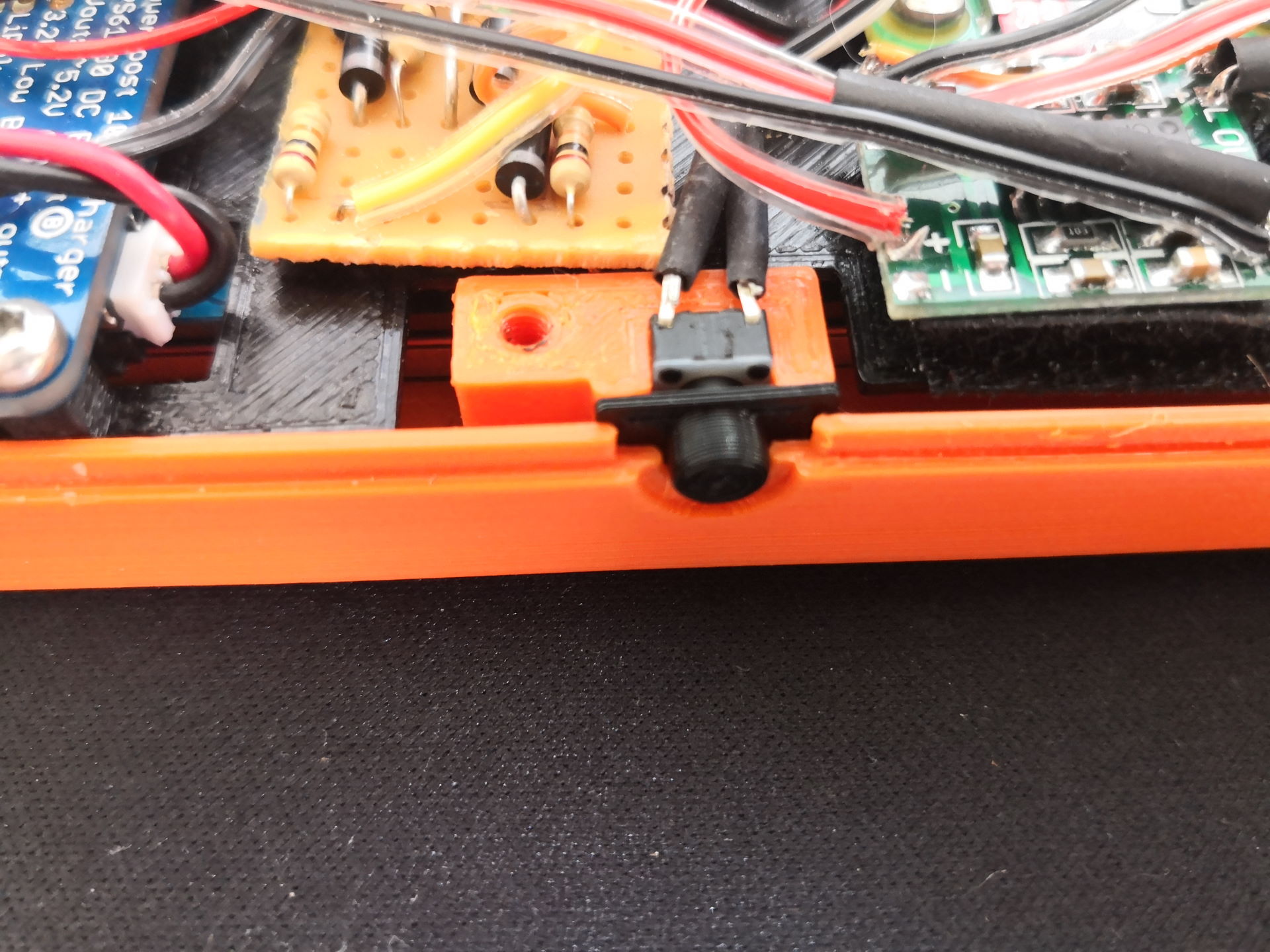
Attach the switch into the bottom of the top shell half. I took a little drop of super glue to fix it in place.
Because the battery monitor and the controller also need several ground wires, I cutted an additional piece of Stripboard of 1x5 in size and used this as a single ground to the Pi.
The simplyRetro Z5 uses Adafruits Retrogame for its controller inputs.
To make the softbuttons work, each button has to be connected to ground and one pin on the Raspberry Pi. I connected the ground pins on the DPad together and used just one ground pin on the Raspberry Pi for all four buttons. I did the same for the four buttons on the right and the Start, Select button. You could also use a piece of Stripboard to just use one ground pin of the Raspberry Pi and connect all ground wires of the buttons just to this Stripboard.
If you want to use the exact same configuration for Retrogame you can use the following pins.
LEFT      16  # Joypad left
RIGHT     17  # Joypad right
DOWN      4   # Joypad down
UP        2   # Joypad up
Z         23  # 'B' button
X         24  # 'A' button
A         0   # 'Y' button
S         25  # 'X' button
Q         26  # Left shoulder button
W         5   # Right shoulder button
SPACE	  22  # 'Select' button
ENTER     27  # 'Start' button
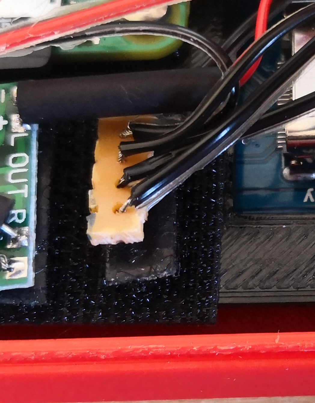
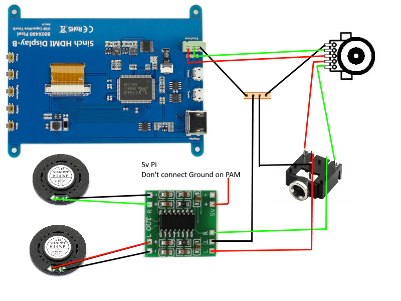
The simyplRetro Z5 takes the audio source directly from the HDMI display. Use a piece of the Stripboard (1x4 in size) as the ground connection. Don't connect the ground of the PAM! Otherwise you will create a ground loop which will cause interferences in you audio circuit!
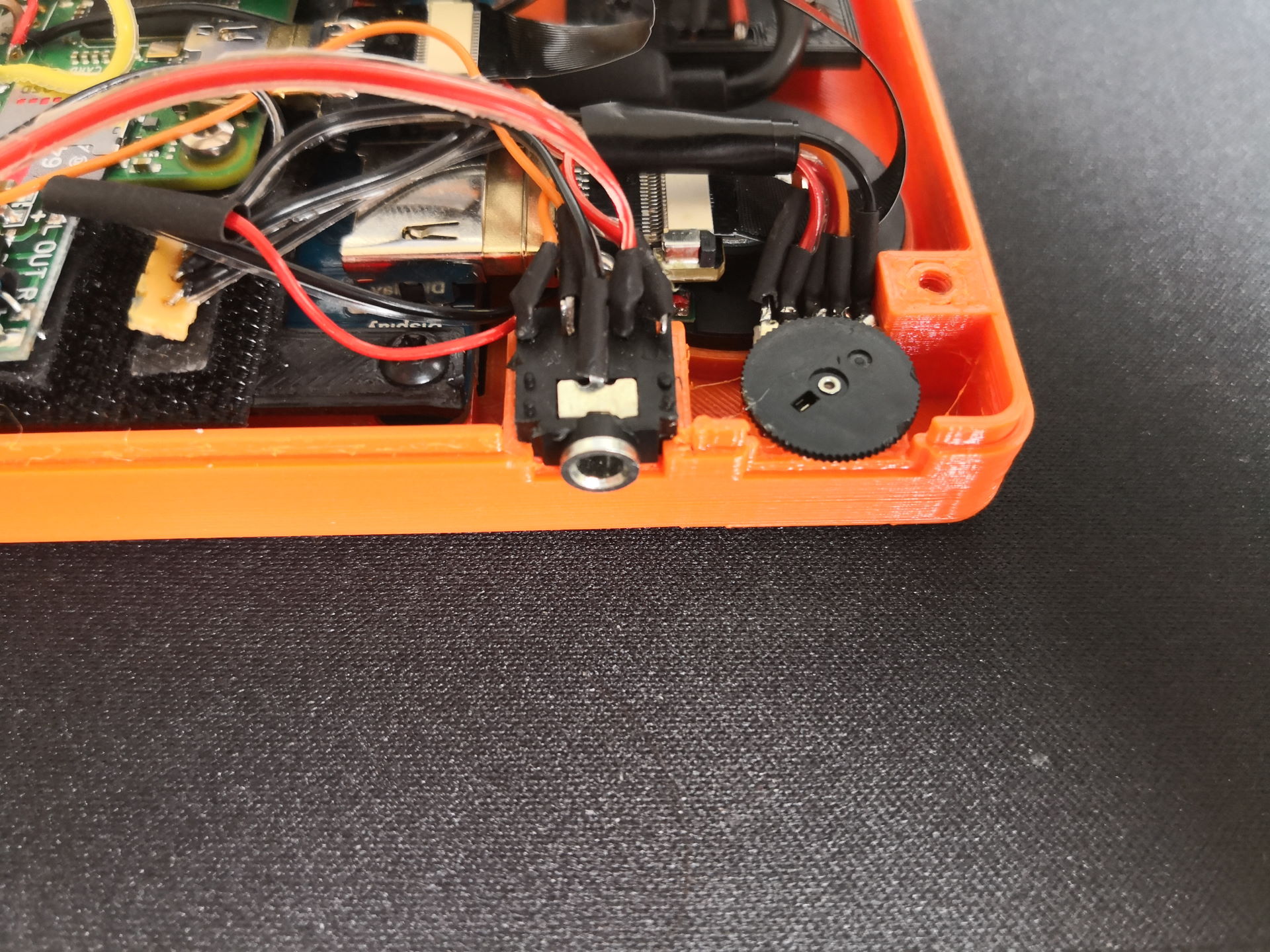
I attached the potentiometer with a little drop of hot glue. The audio jack plug should be press fit.
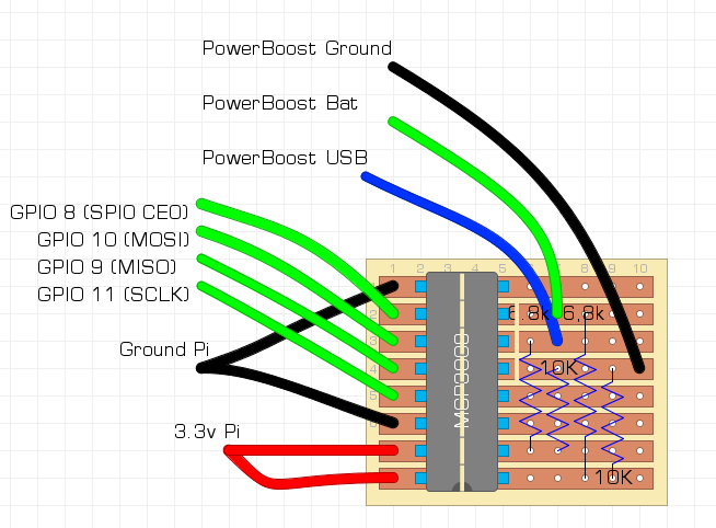
For this step you will again need a bit of the Stripboard, the MCP3008, two 6.8k and two 10k resistors. Again make sure to do the cuts on the Stripboard, before you start soldering. Solder everyhing as referenced in the following picture. You should use the exact same pins, if you want the battery monitor tool in the custom distribution to work.
I attached the board with Velcro on top of the right speaker.
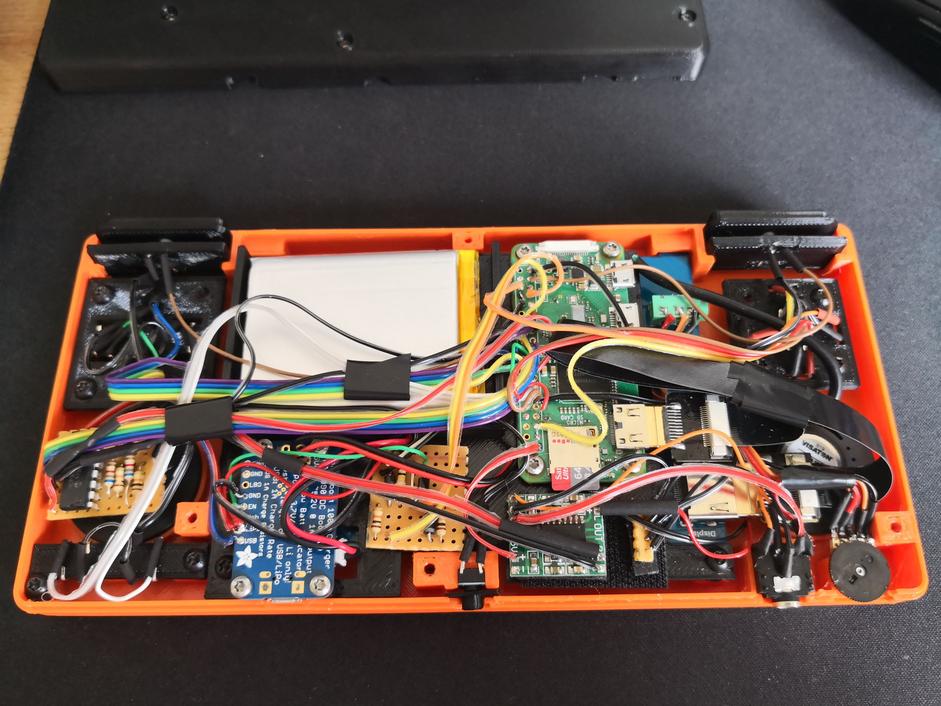
Finally your internals may look something likes this (or not so messy...).
As soon as your SD card is flashed and everything is working, you are able to close the shell. Use five M3x8mm and one M2.5x8mm. Be careful, that the screw holes are free from wires. You don't want to damage them when you screw the shell halves together. After this last step is done, go and enjoy your simplyRetro Z5! Have fun :)
The custom distribution can be downloaded here.
It is based on BuildRoot and just contains the packages needed to play on the Z5.
Please be aware, that the distribution was build for the Z5! It was not tested as a standalone distribution.
The Z5 uses Retroarch for all emulations. The following systems are supported at the moment (more can be added):
- Arcade (MAME2013-plus - BIOS needed)
- Gameboy DMG / Color (Gambatte)
- Gameboy Advance (gpsp - BIOS needed)
- NES (quicknes)
- SNES (snes9x2002)
- Meda Drive / Master System / Sega CD (picodrive - BIOS needed for Sega CD)
If you want to use the distribution just use Etcher to copy the img file to a SD Card.
Please be aware, that the default config.txt will rotate the screen. This is necessary, if you are you using the same screen as me.
The Z5 uses RetroGame by Adafruit for the controller. In this file you are able to set the pins you used during the build.
If you used another GPIO than pin 19 for the power off button, you are able to set it in this file. Please be aware, that you have to use the WiringPi number of the GPIO pin. Use for example https://de.pinout.xyz/ to check the pin numbering. If you don't want to use the battery monitoring and/or power circuit, you are able to change the active features in this file.
Start the system and login with:
User: root
Pass: simplyretro
To use the full size of you SD Card you should execute the following two scripts in order:
/root/reformat.sh (will reboot the system after execution)
/root/resize.sh
You are able to set your WiFi SSID and PSK through the Emulationstation menu. Press 'Start' and go into the 'simplyRetro' menu. After setting the WiFi, just enable any service you need. I recommend to disable the services after usage to reduce battery load and to speed up the boot process.
The ROMs and BIOS folder are located at /root/roms and /root/bios. You are able to change the splash screen, if you want. It is also located at the /root folder.
EmulationStation will ask you to configure your controller on the first start.
Retro Arch is configured to exit a ROM, if you press START + B.
You are able to open the Retro Arch menu while playing a game, if you press START + A.
If there will be an update to the distribution, I will try to distribute the updated files together with the image. This way you are able to update just these files via FTP and don't have to flash the whole image again.
Thanks to NeoHorizon and Craic for the work on the power circuits. I took their work and reworked the circuit a bit and created a custom battery monitor in C.
Thanks to BuildRoot for the creation of this great system which enabled me to create a custom linux distribution.
Thanks to RecalBox for their work on the packages for BuildRoot. I took the RetroArch and LibRetro packages and reworked them a bit to work on my distribution. Also thanks for the code of the on screen keyboard!
Thanks to ehettervik for the emulator splashscreens.
Thanks to ProGM for the GB homebrew game.