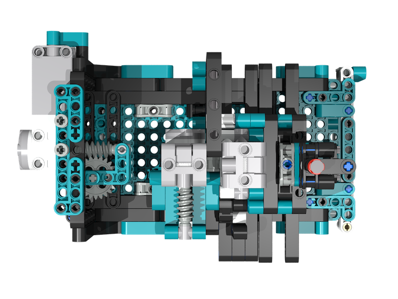
Luke Van In - November 2022
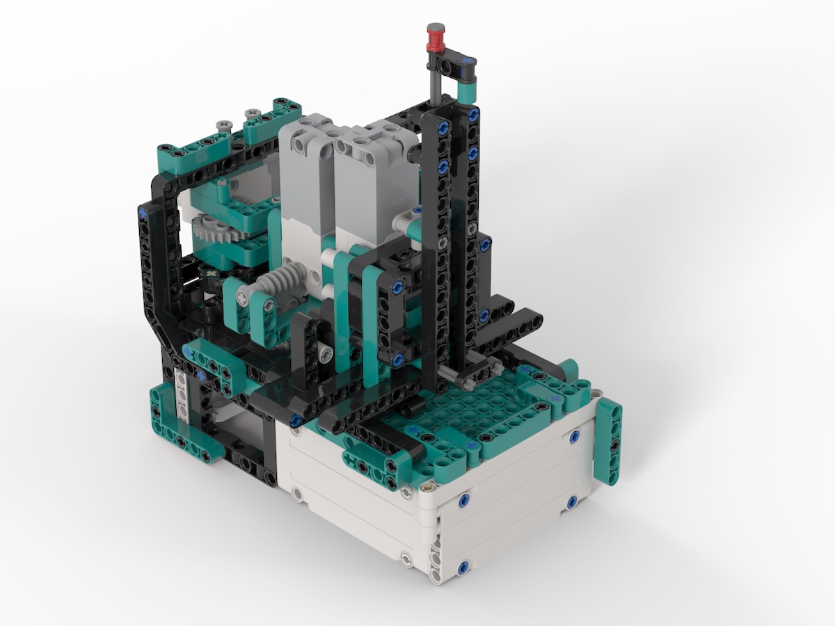
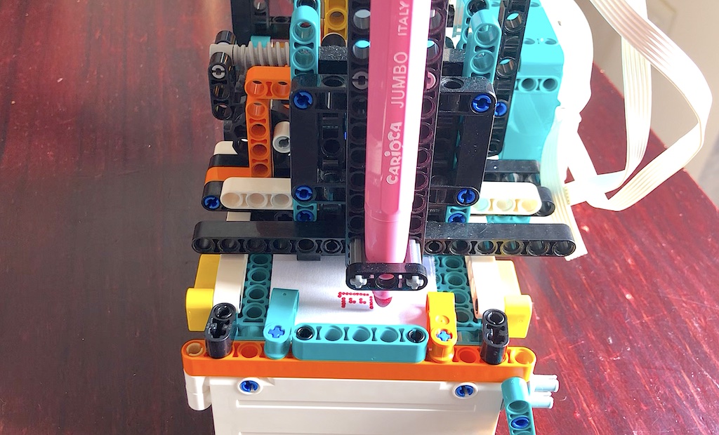
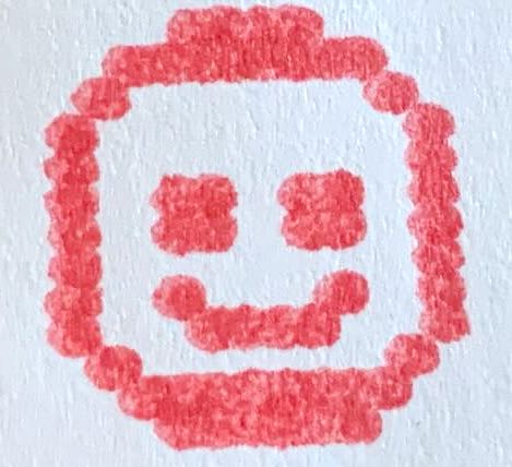
iPad app used to control a 2D (XY) pen plotter using the Lego Mindstorms Robot Inventor or Spike Prime hub. The app is used to create monochrome bitmap images which are drawn by the Lego printer.
The app uses my Swift Mindstorms SDK for controlling the Lego hub over
Bluetooth. See the README in that project repository for details on how the
SDK works.
This source code is provided as an example of controlling Lego Mindstorms or Spike Prime from an iOS application written with the Swift language. The code may be used to control your own printer, modified, and shared.
Here is a timelapse of the printer in action: https://youtu.be/JH-cpd-GQnw
Here is a longer video showing some of the details of the printer: https://youtu.be/fCvV4ZUtqgc
This app can be used on iPad, to create images which are draw on a printer using a Lego Mindstorms Robot Inventor or Lego Spike Prime hub.
Before the Lego hub can be used from the app it needs to be paired with your iPad. This only needs to be done once when the hub is first used, and sometimes after the firmware on the hub is updated.
- Open the Settings app on the iPad, then tap on Bluetooth.
- Make sure that Bluetooth is turned on.
- Turn the hub on and wait for it to start up.
- Press the Bluetooth button on the hub. The blue light on the hub should start flashing and the hub will make an annoying peep-peep noise. Do not be concerned, the noise will soon stop while the blue light continues flashing.
- Wait for the Lego hub to appear on the iPad under Other devices, then tap on it.
- The hub will make a bleeping noise and the blue light will stay on. The Lego hub should appear under My Devices as Connected.
If the app cannot connect to the hub then it may be necessary to remove the device and repeat the steps. Tap the i icon next to the name of the hub, then tap Forget Device. Refer to the documentation from Lego for further troubleshooting and assistance.
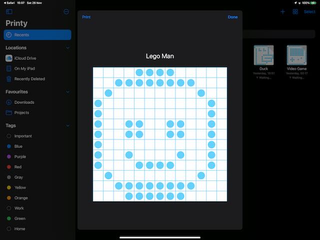
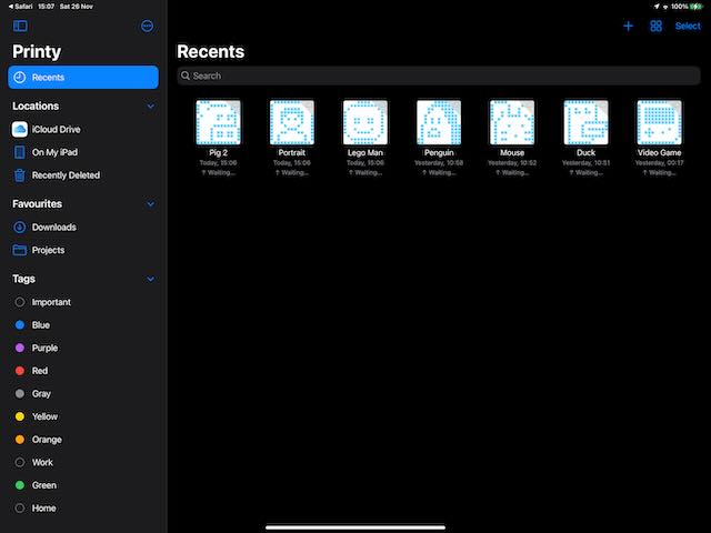
Launch the app. Select an existing compatible image, or create a new image by tapping the "+" button on the navigation bar.
Here you can see my app with a few images I have created:
Tap on a blank square to draw a dot. Tap again to remove an existing dot.
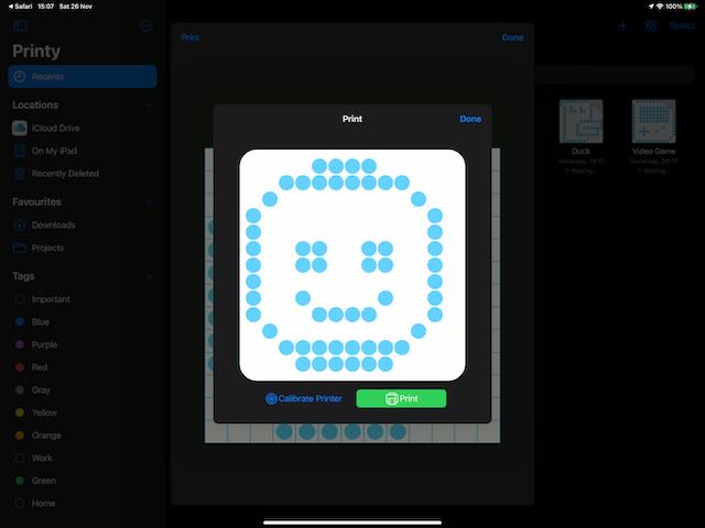
Tap on the Print button on the navigation bar.
Connect to the printer:
- Turn on the Lego hub, then press the Bluetooth button. The blue light should start flashing.
- In the app, tap the Connect to Printer button.
- Wait for the hub to appear in the device list, then tap on it.
- The printer should make a happy bleeping sound when the connection is established.
The app should be able to automatically reconnect to the printer on subsequent uses.
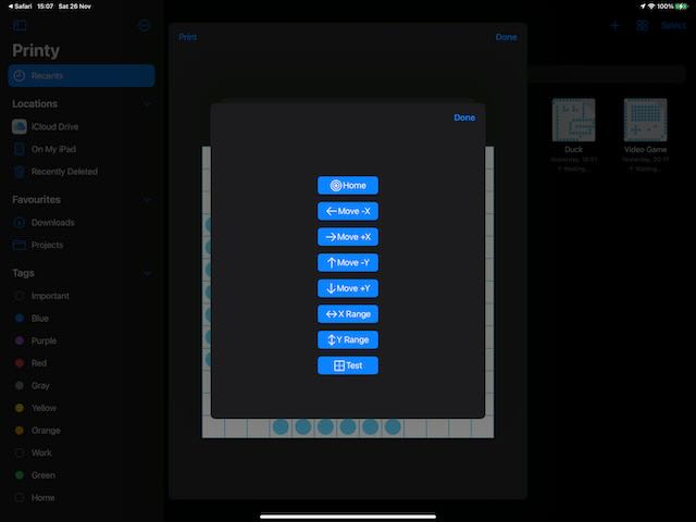
Calibrate the printer: The printer is unable to measure the absolute position of the printer head (pen), and assumes the print head is at the starting position when the print is started. The print head needs to manually moved to the home position the first time the printer is used, or if the printer is disconnected while printing. To position the print head:
- Tap the Calibrate Printer button.
- Hold the Move (+/-)X/Y buttons to move the printer head (pen) to the limit of it's travel.
- Tap the X/Y Range buttons to check that the print head moves the full range left-to-right and back-to-front.
- Tap the Done button to dismiss the popup.
Tap the green Print button to print the image.
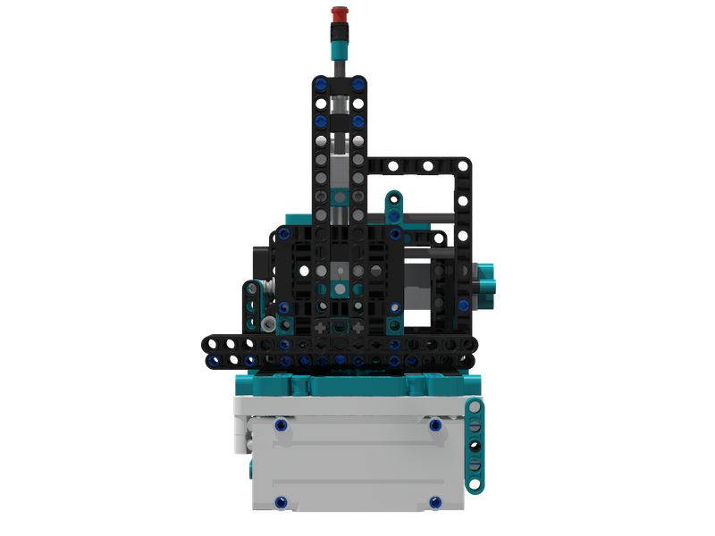
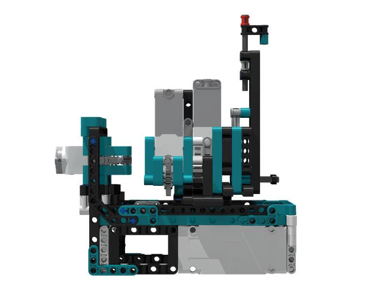
A 3D model of the printer is available for download: Download 3D model
The model may be viewed and edited with BrickLink Studio which can be downloaded for free from the link below: BrickLink Studio 2.0
You may use this model as inspiration to create your own printer if you wish. The design makes use of the Lego pieces that I had available at the time. Some possible improvements are mentioned below:
- Use a rack and pinion, or chain to move the X and Y axes.
- Modify the pen holder to accomodate different stationery.
- Improve the clamping ability of the gate to prevent the paper from shifting during printing.
Be aware that if the geometry of the motor mechanics is changed, then the source code may also need to be modified to compensate for the changes.
While playing with Lego my 7 year old son asked me to make a mechanical press mechanism for a "stamping" machine he was building. One thing led to the next, and over the course of a week the stamping machine evolved into a 2D pen plotter that works as a rudimentary bitmap dot printer. This is a short story of how the printer was developed.
After we assembled the stamper we added motors to automate the stamping mechanism. We added a roller to feed in a strip of paper below the stamper so that it looked like the machine was stamping onto the paper. While it was fun to watch, we decided the stamper would be more interesting if it could actually create an impression on paper.
We tried a few different ways of making markings on paper using various bits of lego to deform the paper, but there were a few problems. The motor was only powerful enough to reliably impress a single dot at a time. We tried using a narrower point to poke holes into the paper, although this required a large amount of force and quickly destroyed the paper sheet after a few holes were punched through it.
It became apparant that an ink stamp or pen would be more practical.A few years before this I had made a device for son that used a pen to draw patterns on an easter egg mounted on a spindle. I borrowed the design for the pen holder I created for that project and mounted it on the stamper. This worked well to create markings.
After adding the pen, I added an extra motor and a sliding mechanism to move the pen on the horizontal axis. The slider used a scotch yoke that was driven by a pin on the motor. The roller would feed the paper into the machine, the second motor would move the pen from side to side, and the stamper would move the pen up and down to draw dots on the paper.
At this point the device could draw images, albeit at low resolution of 7 x 7 dots and witha great amount of distortion. The roller that fed the paper would often slip, and the sliding mechanism would flex instead of sliding, both of which caused uneven gaps between dots.
I replaced the roller with a more reliable gear and rack linear drive. This had a low amount of backlash and provided constant linear motion. I found this design to be superior to the scotch yoke. We unfortunately only have one rack piece, otherwise I would have used gear and rack for all of the axes. This design is the earliest one that can be seen in the videos. I did not have the foresight to record the earlier designs. I eventually replaced the gear and rack with the same scotch yoke used on the horizontal axis for consistency.
This machine was more reliable and could consistently draw somewhat recognisable images with less distortion, but it was still not "good enough".
I rebuilt the machine, changing some of the design to attempt to address some of the problems with rigidity and resolution. The three main changes I made were:
-
Rotated the sliding parts by 90 degrees: The cross section of Lego technic beams is slightly taller that it is wide, which means parts have smaller clearance (less space) in one axis compared to the other. By positioning the sliding rails to take advantage of this I was able to reduce the amount of "play" between parts, which resulted in greater accuracy.
-
Used worm gears: Worm gears provide a high reduction ration. In my printer the reduction is about 22:1, which means the output shaft on the motor needs to perform 22 full revolutions for the output gear to perform 1 revolution. This gives a high amount of accuracy, as even large motor motions result in very tiny output motions. Side effects from the motor such as backlash and inertia are demagnified.
-
Mounted the horizontal drive motor on the carriage: In prior designs, the motor and mechanism used to slide the pen side-to-side was fixed onto the side of the body of the machine. A pin crank from the motor would push inside a long slide that moved along with the pen carriage. This design had an unintended side effect that the carriage would twist by varying amounts due to slop between parts, depending on the position of the pen. This caused a noticable skew in the output. In the rebuild, I instead fixed the motor onto the sliding carriage so that it moves along with the pen.
This is the current state of the design of the machine. The printer is able to consistently output images of 17x17 dots within a space of about 2cm x 2cm. The resolution is mostly limited by the resolvable detail allowed by the nib of the particular marker we are using. Greater detail should be possible by using a pen with a finer nib, which I will try out once I am able to get to the shops.
Assuming a gearing ratio of 22:1, and using 180 degrees of travel for each axis, the printer can in theory address 180 x 22 = 3,960 dots. In reality this is lower:
-
Some of the available angular resolution is used to compensate for backlash. When the motor drives the pen to the starting position, it needs to turn back by some amount to close the gap between the pin that drives the yoke and the edge of the yoke. In my printer this takes a massive 50 degrees, which leaves only 130 degrees of addressable resolution. Backlash could be greatly reduced by using a more direct means to drive the axes, such as by using a gear and rack mentioned previously, or using a sun and planet gear, or by using a chain and sprocket. I may have the parts to for the sun and planet gears, although space is possibly also a limiting factor in the current design.
-
The motor can't really move exactly by single degree increments. The motor takes time to start rotating, and to slow down when stopped, which sometimes causes the motor to overshoot or undershoot the intended angle. Precision seems to decrease as speed increases. Also, the sensor used to measure the motor position is slightly "noisy", and reports changing position even when the motor is stationary. This noise and inconsistency can be filtered out, at the cost of reducing resolution. My estimate of the practical resolvable resolution of the motor is about 5 to 10 degrees.
Considering the above points, a more conservative practical upper limit for resolution could be: (130 ÷ 10) x 22 = 13 x 22 = 286 dots. Not terrible.
My printer currently uses a pin that rotates around the output shaft of the motor to drive the scotch yoke. This translates rotary motion from the motor into linear motion to slide the pen from front-to-back and side-to-side. The geometry causes the pen motion to follow a sinusoidal curve, so that dots near the limits of the image are more closely spaced than dots near the center. The app needs to compensate for this. It is relatively easy for the program to to compensate for this using a bit of geometry to compute how far the motor needs to turn in order to move the pen with consistent linear motion.
[TODO]
