The Pixino board is a ham radio experimental transceiver which is specialized on digital modes and inspired on the algorithms created by Summers (G0UPL) but with a more primitive implementation for experimentation uses only, if you plan to operate seriously on digital modes buy the excellent QRP-Labs QDX kit.
This is a project built on top of the uSDX firmware (QCX-SSB) by Guido (PE1NNZ) with modifications from Pablo (EA2EHC), the approach to involve a Pixie kit with a ham radio project using SDR processing has been explored previously with the Raspberry Pi Z PixiePi project
Initial project setup for HF Arduino controlled Pixie transceiver:
- Operate digital modes with no amplitude information CW and USB (PSK modes).
- LCD 16x2 + encoder based control
- Dual VFO (A/B) for split mode
- VOX & PTT control
- TS-480 CAT command
- Operates 7.0-7.3 MHz
- Largely inspired from Guido (PE1NNZ) with QCX-SSB [here] (https://github.com/threeme3/usdx)
- Code excerpts and processing algorithms taken from my own projects Pi4D/PixiePi
- Taping on ideas and work from WB2CBA ADX concepts and ideas [here] (//https://github.com/WB2CBA/ADX)
- Algorithms for frequency detection from Burkhard Kainka(DK7JD) [here] (http://elektronik-labor.de/HF/SDRtxFSK2.html)
- Operates with both the standard QCX-SSB and QDX algorithm as described by Hans [here] (https://www.qrp-labs.com/images/qdx/manual_operation_1_03.pdf)
The Pixie QRPp (very low power, less than 1W output) transceiver is a very popular DIY project among hams as it is very easy to build, test and operate from the electronic standpoint, yet able to perform some actual limited communications (QSO) over the air.
Although really small power can be enough to sustain communications over great distances and therefore not being a per se limiting factor there are other factors in the basic implementation which makes difficult to carry communications except on very favorable conditions.
An explanation of how the transceiver work can be found here.
This project starts with a working Pixie transceiver (a cheap kit bought at eBay or other sellers) and to integrate it with an Arduino Nano board controlling a Si5351 board to provide the signal generation and other functionality.
Instead of a crystal based signal generation DDS is be used. The rest of the code deals mostly with the user interface and operating features, among others:
From the firmware standpoint this project has been largely inspired by the work from Guido (PE1NNZ) and in particular by the QCX-SSB project and the entire echosystem around it, the version used as the starting point were the one made by Pablo (EA2EHC).
Also my own work with the projects PixiePi and OrangeThunder had been largely used to extract code and ideas for this project.
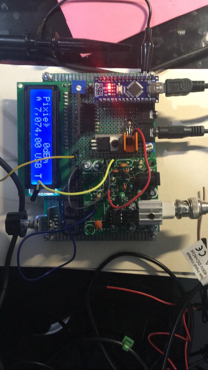
This is a snapshot of the current prototype used to develop and debug this project:
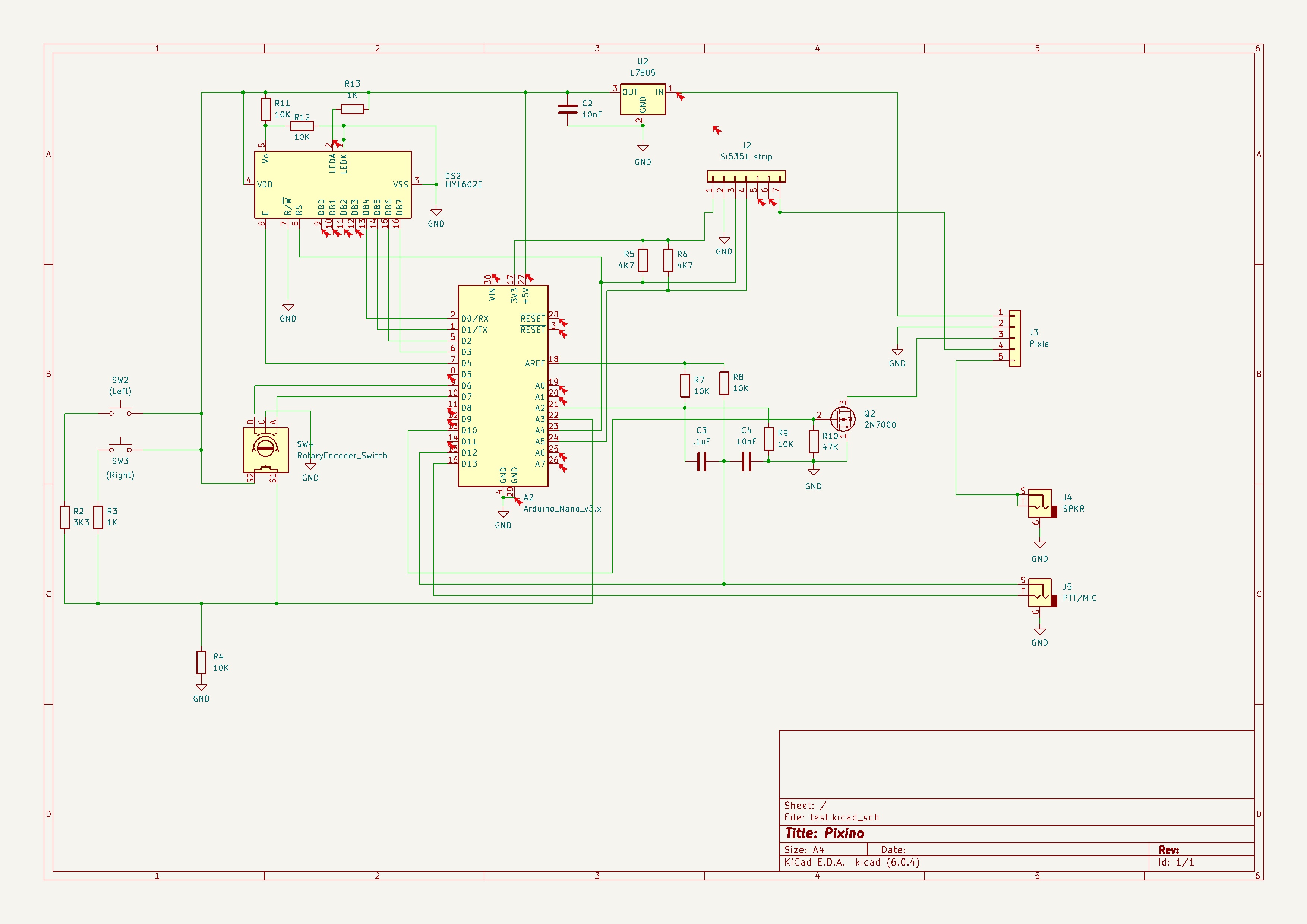
The original design from Guido (PE1NNZ) based on the QCX design from Hans Summers (G0UPL) at QRP-Labs
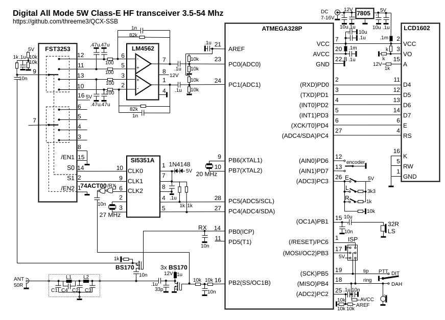
Some small modifications to adapt the controller to operate with a Pixie design, basically:
- Then entire reception block of the uSDX is not implemented, the receiver is a DC one provided by the Pixie module.
- CLK2 is routed as a X-tal replacement on the Pixie, it is enabled both during RX and TX to feed the receiver and transmitter function.
- CLK1/0 are left unused.
- A PTT circuit is added to operate the KEY control of the Pixie board.
- No speaker, ISP.
- The transmitter chain is replaced by the Pixie module.
- Encoder is moved from PD6/PD7 (D6-D7) to PD5/PB0 (D5-D8) to clear D6/D7 to be used as AIN0/AIN1 for the ADX algorithm.
The circuit used is as follows
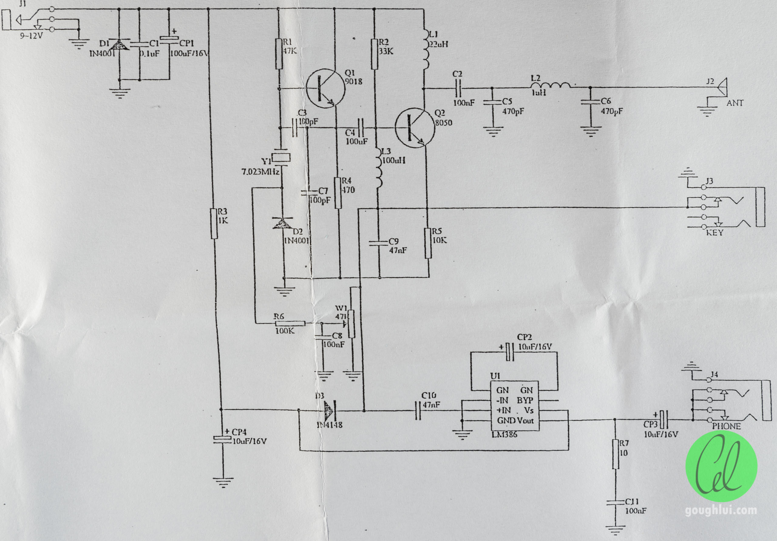
A typical circuit for the kit might be:
Some minor modifications are needed while building the Chinese DIY Pixie kit, other versions might vary.
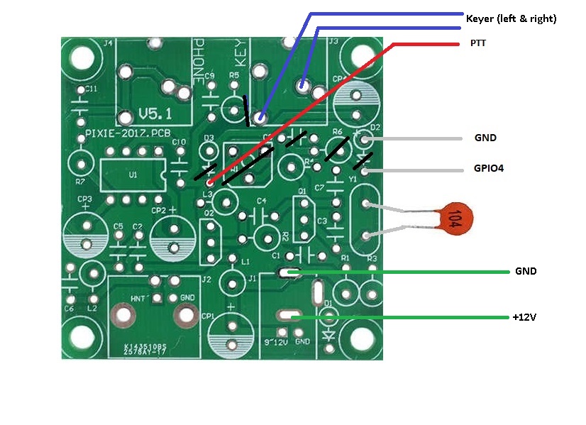
The following components needs not to be placed when building the kit
* D2 - Diode 1N4001
* R6 - R 100K
* C8 - C 100nF
* W1 - R 47K (var)
* D3 - Diode 1N4148
* Y1 - Cristal 7.032 MHz
* Connect Cx=100 nF on the same place than Y1 on the kit.
* Connect negative side of D3 diode to the interface board PTT line
* Cut trace from R5 to KEY socket, connect both keyer legs to the socket going into GPIO15 and GPIO13.
* Assure all three boards (interface, Pixie and Raspberry Pi) share a common ground.
* Extract +12V from the Pixie +12V socket, feed LM7805 with it, then feed the Raspberry Pi Zero board with it.
All additional interface circuitry might be constructed on a prototype perfboard or using the Manhattan technique.
Operating with a 12V supply the final transistor might become quite hot and indeed fail if the keydown period is long enough (as it might be with FT8 or WSPR, even for slow CW). A small heatsink is recommended. Space is very limited on typical kits but a small piece of aluminum might be enough, be aware not to short either L1 nor L3 with it.
The keyer transistor Q1 will benefit from a heat sink as well if long keying times are expected, a cooler fan can be turned on with the KEYER line if needed.
At some locations the Chinese DIY Pixie kit might be subject to heavy BCI, in order to minimize try to replace R3 from 1K to 47-100 Ohms.
An interesting set of low cost modifications to increase the power, improve efficiency and other enhancements to the original DIY Kit can be found at link.
Even if the Pixie schematic is used for the project the software could be used directly with other DIY or homebrew popular designs, among others:
Lots of good QRPp projects can be found at link or SPRAT magazine link.
This project isn't a serious alternative to some excellent DIY Kits available in the market, which deliver tons of good features at reasonable cost. This project must be seen as a learning platform enabling a very cheap DIY kit with tons of features their intrisic limitations can not be extended to cover. In particular this kit is NOT a replacement nor an alternative to the following superb kits that I'm aware of:
- QRP Lab's (Hans Summers) ANY product from QRP-Labs.
- CRKits (Adam Rong's) D4D kit.
- QRPGuys's DSB Digital Transceiver.
- 4S QRP Group's Cricket 40.
- ... and other similar projects ...
For all of them do yourself a favor and buy a kit, assemble it and enjoy the experience.
Not to mention other relatively higher scale setups such as the BitX, mcHF or minion SDR transceivers and, of course, all variants of the uSDX/uSDR projects.
This is a pure, non-for-profit, project being performed in the pure ham radio spirit of experimentation, learning and sharing. This project is original in conception and has a significant amount of code developed by me, it does also being built up on top of a giant effort of others to develop the base platform and libraries used. Therefore this code should not be used outside the limits of the license provided and in particular for uses other than ham radio or similar experimental purposes. No fit for any purpose is claimed nor guaranteed, use it at your own risk. The elements used are very common and safe, the skills required very basic and limited, but again, use it at your own risk. Despite being a software enginering professional with access to technology, infrastructure and computing facilities of different sorts I declare this project has been performed on my own time and equipment. This project must not be seen as a replacement for other fine kits such as the QCX, D4D, QRPGuys and similar; after all it's based on just a USD 4.- Pixie board, so it can be compared and used with other similar boards as well as long as the Xtal can be replaced by a DDS.
No true ham project is finished until some on-the-air tests are performed, and this project isn't an exception.
Although the firmware allow several modes to be explored such as CW, PSK and Weak Signal modes (any mode that doesn't require amplitude modulation or
linear behaviour) the FT8 mode is particularly suitable for this project.
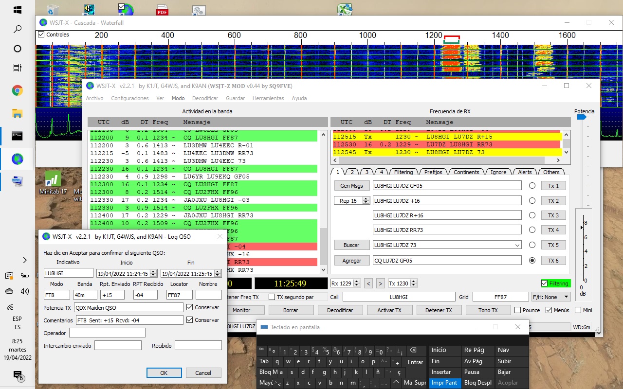
A maiden QSO was made
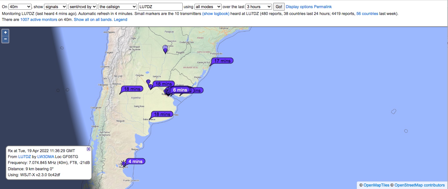
 Also some reports were gathered from the PSK Reporter site link which can be seen
- Add secondary connection and ADX MIC filter
- Prototype wiring for stand-alone +12V operation (internal +5V regulator).
- Add receiver functions to measure signal strength (wire SPKR to A0, polarization, enable Simple_RX, etc.)
- Add transmitter function to show audio level at the S-Meter
- Customize useful functions in and non-useful functions on QCX-SSB firmware out.
- Incorporate VOX mode for transmission.
- Enable, test and deploy CAT work.
- Re-wire external keyer.
- Box.
- PCB.
- Add memory meassuring function.
