Disclaimer: I am heavily re-using code of an existing project called Audio Reactive LED Strip by Scott Lawson. See below for the description of the original project. Please have a read through that, as it explains all of the basics around how to run the python code. I currently only use the "Computer + ESP8266" mode which I have extended to support multiple LED strip clients over a server broadcast and client registration (see client_management.py )
This project aims at developing a hybrid LED system that can be used (i) on a fixed location and (ii) on foot when moving around. When multiple LED clients are in the same location, the light show will be sychronised, which which should look nice at the bar, on bikes, or when walking around.
The basic idea is to have:
- a series of LED "things" (LED clients) who are all being fed a light show by a
- server (either one of the clients or a dedicated server machine)
To keep everything "mobile" we need some wireless communication as well as power from a battery.
There are different modes of operations, currently the following 3 are envisioned:

To see whether this is feasible, I have created a demo that is recorded here: https://youtu.be/f2kS4P1rJ0Y
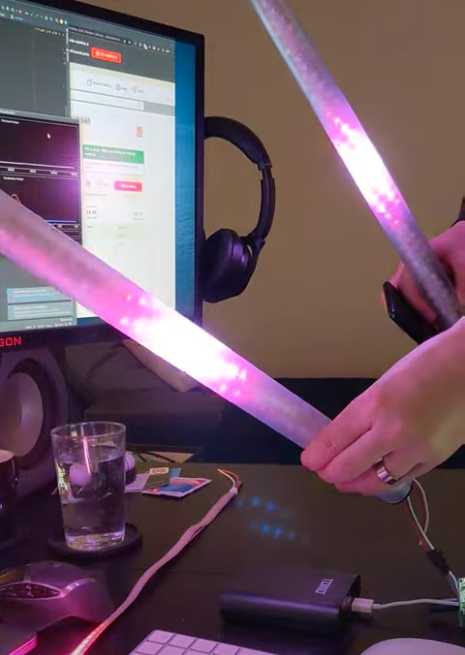 (click to play)
- Build demo led tube and get others onboard
- Brainstorm other/better/larger LED setups (currently we use strips)
- Sync with Chef Juke about laser cutting acrylic discs so we could build a tube full of them looking a bit like this
- Implement different resolutions (currently only 140 LED resolution supported)
- Figure out power (battery power)
- Figure out charging situation (using charge controller or through removable 18650s?)
- Design a handle that can be 3d-printed + easily re-charged overnight
- Add status LEDs to circuit and code
- Implement dynamic network ports (so we can restart faster)
To build the sample tubes, I used ideas that I found in this video:
- I used a bunch of acrylic tubes (30mm/32mm inside/outside diameter - clear ones as amazon.co.uk didn't stock anything else)
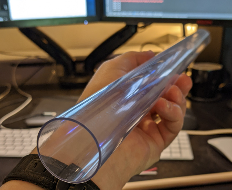 . I sanded them using 600 grit and then 1500 grit sandpaper to get them to diffuse the light.
 - I used 3D printed end caps (lid.v2.stl and lid.v2.with_hole both in lid.v2.with_hole.2x.gcode ready to be printed):
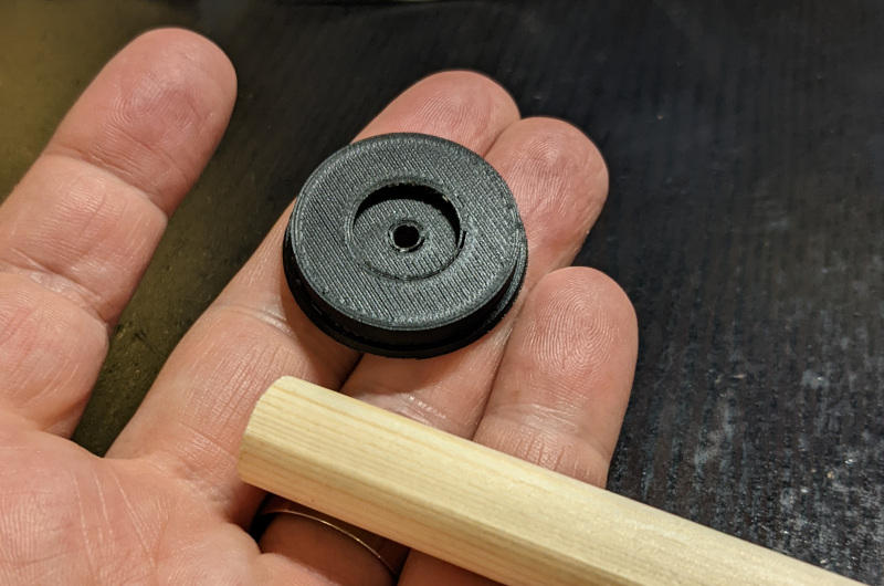
- I then rolled the LED strip around the dowel (superglued each end) and closed the sides (one of the caps has a hole for the cables):
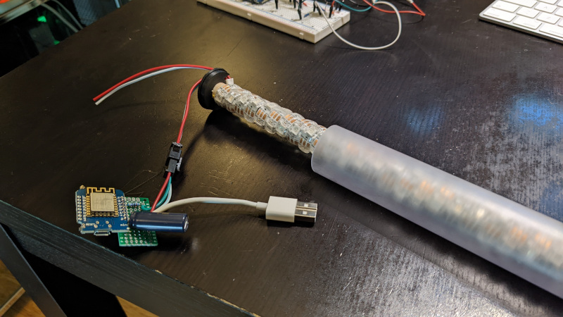
- For the circuit I pretty much used the NeoPixel Wiring Diagram from Adafruit. The only difference that I had is that I used the ESP8266, so the data pin is the RX pin. Currently I power the thing over 5V/Gnd using a USB cable of which I only use the 5V/GND cables (also I didn't have any 1000uF capacitors, so I used 2200uF ones):


To run one of these tubes you need:
- a mac or pc running python 3 (2 is not fully supported)
- a wifi access point in your network
- (~$5) an ESP8266 (I bought 10 for £25)
- (~$8) an WS2812B LED strip (I used 60 LEDs/m strips from AliExpress, 5m is enough for two 0.5m tubes)
- (~5-10) an acrylic/polycarbonate/pet tube (if you find a 30mm/32mm one, you can use the lids from above)
- a 14mm diameter wooden dowel, same length as the tube (minus 4mm, 2 each side for the cap)
- two wood screws 3x25mm
- a 470 Ohms resistor
- A 1000 uF capacitor
Real-time LED strip music visualization using Python and the ESP8266 or Raspberry Pi.


The repository includes everything needed to build an LED strip music visualizer (excluding hardware):
- Python visualization code, which includes code for:
- Recording audio with a microphone (microphone.py)
- Digital signal processing (dsp.py)
- Constructing 1D visualizations (visualization.py)
- Sending pixel information to the ESP8266 over WiFi (led.py)
- Configuration and settings (config.py)
- Arduino firmware for the ESP8266 (ws2812_controller_esp8266.ino)
To build a visualizer using a computer and ESP8266, you will need:
- Computer with Python 2.7 or 3.5 (Anaconda is recommended on Windows)
- ESP8266 module with RX1 pin exposed. These modules can be purchased for as little as $5 USD. These modules are known to be compatible, but many others will work too:
- NodeMCU v3
- Adafruit HUZZAH
- Adafruit Feather HUZZAH
- WS2812B LED strip (such as Adafruit Neopixels). These can be purchased for as little as $5-15 USD per meter.
- 5V power supply
- 3.3V-5V level shifter (optional, must be non-inverting)
Limitations when using a computer + ESP8266:
- The communication protocol between the computer and ESP8266 currently supports a maximum of 256 LEDs.
You can also build a standalone visualizer using a Raspberry Pi. For this you will need:
- Raspberry Pi (1, 2, or 3)
- USB audio input device. This could be a USB microphone or a sound card. You just need to find some way of giving the Raspberry Pi audio input.
- WS2812B LED strip (such as Adafruit Neopixels)
- 5V power supply
- 3.3V-5V level shifter (optional)
Limitations when using the Raspberry Pi:
- Raspberry Pi is just fast enough the run the visualization, but it is too slow to run the GUI window as well. It is recommended that you disable the GUI when running the code on the Raspberry Pi.
- The ESP8266 uses a technique called temporal dithering to improve the color depth of the LED strip. Unfortunately the Raspberry Pi lacks this capability.
Visualization code is compatible with Python 2.7 or 3.5. A few Python dependencies must also be installed:
- Numpy
- Scipy (for digital signal processing)
- PyQtGraph (for GUI visualization)
- PyAudio (for recording audio with microphone)
On Windows machines, the use of Anaconda is highly recommended. Anaconda simplifies the installation of Python dependencies, which is sometimes difficult on Windows.
Create a conda virtual environment (this step is optional but recommended)
conda create --name visualization-env python=3.5
activate visualization-env
Install dependencies using pip and the conda package manager
conda install numpy scipy pyqtgraph
pip install pyaudio
The pip package manager can also be used to install the python dependencies.
pip install numpy
pip install scipy
pip install pyqtgraph
pip install pyaudio
If pip is not found try using python -m pip install instead.
On macOS, python3 is required and portaudio must be used in place of pyaudio.
If you don't have brew installed you can get it here: https://brew.sh
brew install portaudio
brew install pyqt5
pip3 install numpy
pip3 install scipy
pip3 install pyqtgraph
pip3 install pyaudio
Running the visualization can be done using the command below.
python3 visualization.py /tmp
ESP8266 firmare is uploaded using the Arduino IDE. See this tutorial to setup the Arduino IDE for ESP8266.
Download Here or using library manager, search for "NeoPixelBus".
The ESP8266 has hardware support for I²S and this peripheral is used to control the ws2812b LED strip. This significantly improves performance compared to bit-banging the IO pin. Unfortunately, this means that the LED strip must be connected to the RX1 pin, which is not accessible in some ESP8266 modules (such as the ESP-01).
The RX1 pin on the ESP8266 module should be connected to the data input pin of the ws2812b LED strip (often labelled DIN or D0).
For the NodeMCU v3 and Adafruit Feather HUZZAH, the location of the RX1 pin is shown in the images below. Many other modules also expose the RX1 pin.


Since the Raspberry Pi is a 3.3V device, the best practice is to use a logic level converter to shift the 3.3V logic to 5V logic (WS2812 LEDs use 5V logic). There is a good overview on the best practices here.
Although a logic level converter is the best practice, sometimes it will still work if you simply connect the LED strip directly to the Raspberry Pi.
You cannot power the LED strip using the Raspberry Pi GPIO pins, you need to have an external 5V power supply.
The connections are:
- Connect GND on the power supply to GND on the LED strip and GND on the Raspberry Pi (they MUST share a common GND connection)
- Connect +5V on the power supply to +5V on the LED strip
- Connect a PWM GPIO pin on the Raspberry Pi to the data pin on the LED strip. If using the Raspberry Pi 2 or 3, then try Pin 18(GPIO5).
- Install Python and Python dependencies
- Install Arduino IDE and ESP8266 addon
- Download and extract all of the files in this repository onto your computer
- Connect the RX1 pin of your ESP8266 module to the data input pin of the ws2812b LED strip. Ensure that your LED strip is properly connected to a 5V power supply and that the ESP8266 and LED strip share a common electrical ground connection.
- In ws2812_controller.ino:
- Set
const char* ssidto your router's SSID - Set
const char* passwordto your router's password - Set
IPAddress gatewayto match your router's gateway - Set
IPAddress ipto the IP address that you would like your ESP8266 to use (your choice) - Set
#define NUM_LEDSto the number of LEDs in your LED strip
- Upload the ws2812_controller.ino firmware to the ESP8266. Ensure that you have selected the correct ESP8266 board from the boards menu. In the dropdown menu, set
CPU Frequencyto 160 MHz for optimal performance. - In config.py:
- Set
N_PIXELSto the number of LEDs in your LED strip (must matchNUM_LEDSin ws2812_controller.ino) - Set
UDP_IPto the IP address of your ESP8266 (must matchipin ws2812_controller.ino) - If needed, set
MIC_RATEto your microphone sampling rate in Hz. Most of the time you will not need to change this.
If you encounter any problems running the visualization on a Raspberry Pi, please open a new issue. Also, please consider opening an issue if you have any questions or suggestions for improving the installation process.
Download and extract all of the files in this repository onto your pi to begin.
Install python dependencies using apt-get
sudo apt-get update
sudo apt-get install python-numpy python-scipy python-pyaudio
For the Raspberry Pi, a USB audio device needs to be configured as the default audio device.
Create/edit /etc/asound.conf
sudo nano /etc/asound.conf
Set the file to the following text
pcm.!default {
    type hw
    card 1
}
ctl.!default {
    type hw
    card 1
}
Next, set the USB device to as the default device by editing /usr/share/alsa/alsa.conf
sudo nano /usr/share/alsa/alsa.conf
Change
defaults.ctl.card 0
defaults.pcm.card 0
To
defaults.ctl.card 1
defaults.pcm.card 1
- cd rpi_ws281x/python/examples
- sudo nano strandtest.py
- Configure the options at the top of the file. Enable logic inverting if you are using an inverting logic-level converter. Set the correct GPIO pin and number of pixels for the LED strip. You will likely need a logic-level converter to convert the Raspberry Pi's 3.3V logic to the 5V logic used by the ws2812b LED strip.
- Run example with 'sudo python strandtest.py'
In config.py, set the device to 'pi' and configure the GPIO, LED and other hardware settings.
If you are using an inverting logic level converter, set LED_INVERT = True in config.py. Set LED_INVERT = False if you are not using an inverting logic level converter (i.e. connecting LED strip directly to GPIO pin).
The visualization program streams audio from the default audio input device (set by the operating system). Windows users can change the audio input device by following these instructions.
Examples of typical audio sources:
- Audio cable connected to the audio input jack (requires USB sound card on Raspberry Pi)
- Webcam microphone, headset, studio recording microphone, etc
You can use a "virtual audio device" to transfer audio playback from one application to another. This means that you can play music on your computer and connect the playback directly into the visualization program.

On Windows, you can use "Stereo Mix" to copy the audio output stream into the audio input. Stereo Mix is only support on certain audio chipsets. If your chipset does not support Stereo Mix, you can use a third-party application such as Voicemeeter.

Go to recording devices under Windows Sound settings (Control Panel -> Sound). In the right-click menu, select "Show Disabled Devices".

Enable Stereo Mix and set it as the default device. Your audio playback should now be used as the audio input source for the visualization program. If your audio chipset does not support Stereo Mix then it will not appear in the list.
Linux users can use Jack Audio to create a virtual audio device.
On OSX, Loopback can be use to create a virtual audio device.
Once everything has been configured, run visualization.py to start the visualization. The visualization will automatically use your default recording device (microphone) as the audio input.
A PyQtGraph GUI will open to display the output of the visualization on the computer. There is a setting to enable/disable the GUI display in config.py

If you encounter any issues or have questions about this project, feel free to open a new issue.
- ESP8266 supports a maximum of 256 LEDs. This limitation will be removed in a future update. The Raspberry Pi can use more than 256 LEDs.
- Even numbers of pixels must be used. For example, if you have 71 pixels then use the next lowest even number, 70. Odd pixel quantities will be supported in a future update.
This project was developed by Scott Lawson and is released under the MIT License.