Due to updates to the Daly library dependency, compilation might throw an error. Please look at the Issues page for the temporary solution while I do further testing, or use the older version of the Daly lib which is in the Arduino dependencies folder. !!!
ESP32 bridge allowing Daly Smart BMS to be used with a Sofar inverter/charger (and others that use SMA CANBUS protocol).

It connects to Daly via UART and transmits to the inverter on CANBUS (SMA protocol). At the same time, it will transmit the BMS data to an MQTT broker if it can connect to your WiFi. If it can't connect to WiFi or your MQTT broker, it will still work as a BMS-to-Inverter bridge. The icons on the OLED represent the WiFi & MQTT status. They will be crossed out if there is no connection.
Data comms is one way only - data is requested from Daly and sent to the Inverter & over MQTT. May be compatible with other inverters that use the SMA protocol.
My testing showed that Daly UART port works on 3.3v. PLEASE measure yours before connecting the ESP. Some users report 5V.


USE THIS AT YOUR OWN RISK! Batteries are dangerous. Don't come to me if you burn your house down. This release is a working prototype. It might freeze, there might be glitches. Your battery might overcharge/undercharge. Make sure your BMS is set up properly with your own limits. USE THIS AT YOUR OWN RISK!

Some battery setups earth the battery negative, others don't. For the ones that aren't earthed, you may get a ID05 Fault on the inverter when you connect canbus. You might get a shock if you touch the comms/3v3/ground pins coming from the BMS, even though they're supposed to be only 3.3v.
Ask me how I know!
This is because the Daly UART ground is battery ground, and it makes its way to the inverter. It might be higher or lower voltage potential, in respect to earth.
The Daly needs to be isolated in this case, using a digital isolation IC. Opto-coupler's don't work as the signal becomes inverted. ESP32 serial can be inverted by software but Daly can't. IL716-3E based isolator IC works, as well as the cheap off-the shelf ADUM1201 based modules.
Make sure the I2C pins are mapped correctly for the Oled to work. For me, pins 21 and 22 work great C:\Users\XXXXX\Documents\Arduino\libraries\Adafruit_SSD1306-1.1.2\Adafruit_SSD1306.cpp
#define I2C_SDA 21
#define I2C_SCL 22
And also Serial2 needs to be correctly mapped in this file (This is Windows. Sorry I don't know where it is on a Mac) C:\Users\XXXXX\AppData\Local\Arduino15\packages\esp32\hardware\esp32\1.0.6\cores\esp32\HardwareSerial.cpp Look for this near the top:
#ifndef RX2
#define RX2 16
#endif

#ifndef TX2
#define TX2 17
#endif
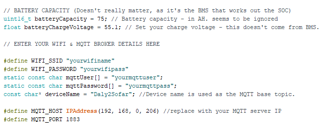
Add your WiFi and MQTT details to the top of the sketch, as well as your battery capacity and preferred charging voltage (Capacity is broken at the moment, but the Inverter seems happy nonetheless):
Subscribe your MQTT client to:
Daly2Sofar/state
topics published are:
soc
voltage
current
power
temp
lowestcell
highestcell
cellimbalance
For extracting the data into Home Asisstant sensors, use Node-Red. You can import the Daly2Sofar Node-Red to Home Assistant flow.jsonflow to extract the data into sensor entities, it will look like this:

(you may need to install Moving Average filter if you want smoothing of data)
When the battery is discharging, Node-RED will calculate the remaining battery time based on the current discharge rate. When it's charging, it will calculate the time left to full charge. Because charging/discharging and SOC isn't linear, this value is only a rough estimation, but useful nonetheless.
This has some hard-coded variables - it's based on a 10kWh battery and 80% DOD, and also what percentage to consider 'full' 95% in my case.
Make sure you customise them if you want to use this Flow :-)

Home Assistant dashboard example

- Do proper CANBUS status check. Currently, CAN indicator will go live after the data send, whether it's succesfull or not.
- Add battery cycles: the owner of the Daly library is adding the functionality, and it will be reflected here when it's done.
- Add charge/discharge control via MQTT (as soon as it's available in the Daly lib)
- Tidy up code/refactor where poss.
- Longer term stability testing.
https://github.com/maland16/daly-bms-uart
https://github.com/miwagner/ESP32-Arduino-CAN
https://github.com/me-no-dev/AsyncTCP
https://github.com/marvinroger/async-mqtt-client
https://github.com/adafruit/Adafruit_SSD1306
CANH & CANL can be live swapped. If display is saying all is good but inverter isn't happy, try swapping the wires.
Developed on Arduino IDE 1.8.5. Version 1.8.14 failed to compile. Downgrade if you have issues
Using arduino ESP32 Core version 1.0.6
Developed & tested with a Sofar HYD6000-ES. Should work fine with all the others, but if you test it on your inverters let me know how it goes!
Using SMA_CAN_protocol.pdf for the CAN IDs and data format info (google will find you the PDF)
Using https://cryptii.com/pipes/integer-encoder for working out hex values
VIEW TEXT > DECODE INTEGER (LITTLE ENDIAN) U16 > VIEW BYTES HEX GROUPED BY BYTES
https://www.scadacore.com/tools/programming-calculators/online-hex-converter/ for checking hex values