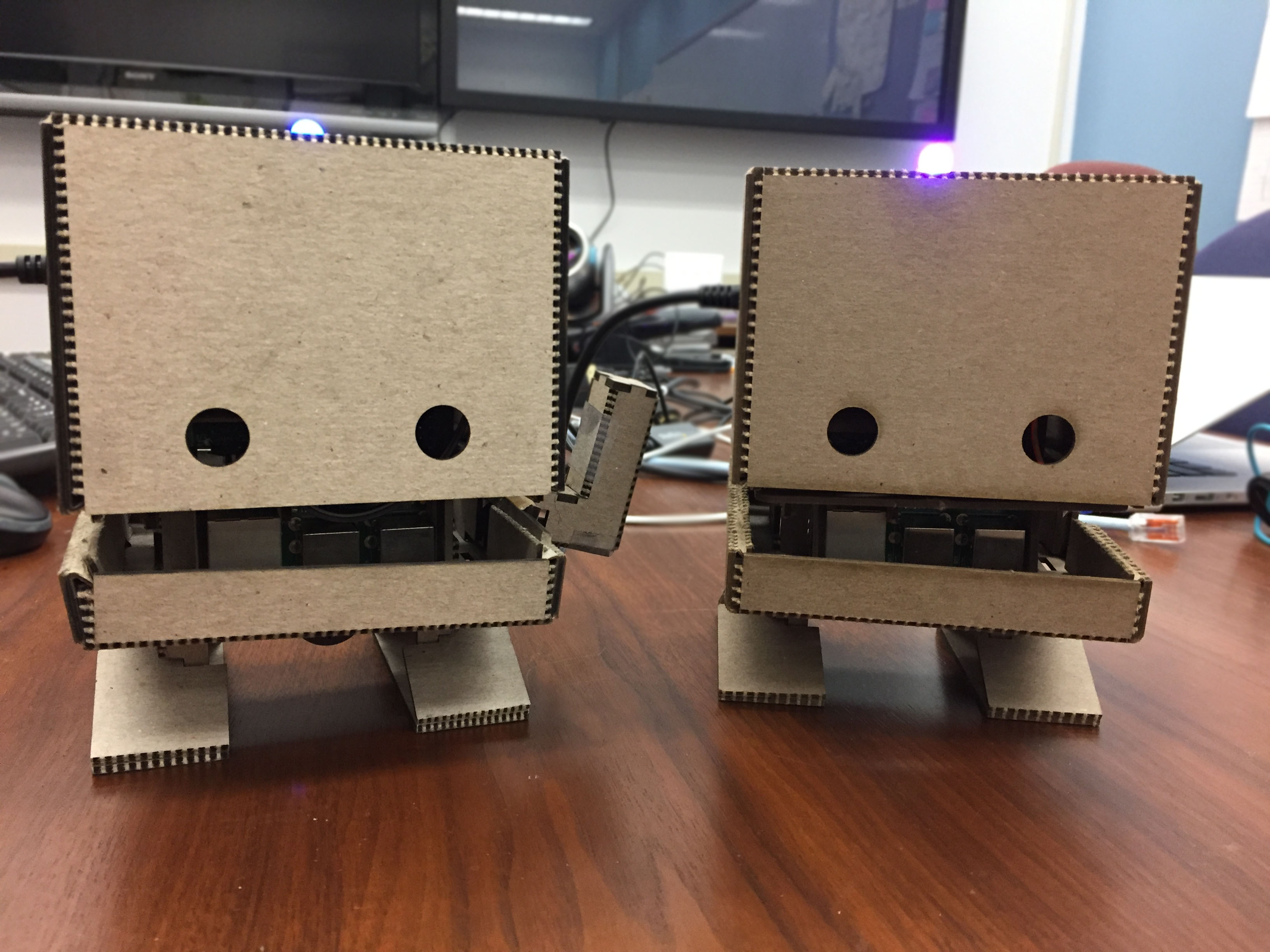
IBM Watson Maker Kits are a collection of DIY open source templates to build things with Watson in a fun and easy way. IBM TJBot is the first maker kit in the collection. You can 3D print or laser cut the robot body, then use one of our recipes to bring him to life!
In addition, you can unleash your own creativity and create new recipes that bring TJBot to life using any of the available Watson services!
TJBot only works with a Raspberry Pi.
You can make your own TJBot in a number of ways.
- 3d Print or Laser Cut. If you have access to a 3D printer or laser cutter, you can print/cut TJBot yourself. Begin by downloading the design files and firing up your printer/cutter.
- TJBot Full Kit. You can order a full TJBot kit with the laser cut cardboard and all the electronics from Sparkfun, Adafruit, or Robotkingdom.
- TJBot Cardboard Kit. You can purchase the TJBot laser cut cardboard from Texas Laser Creations.
There are a number of components you can add to TJBot to bring him to life. Not all of these are required for all recipes.
- Raspberry Pi 3 + SD card preloaded with NOOBS. This is a required component to make TJBot work! 🤖
- NeoPixel RGB LED (8mm). Note that if you are using other kinds of LEDs, you may need to add a resistor; this LED doesn’t require one.
- Female-to-female jumper wires. TJBot will only need 3 of these wires, so you’ll have extra.
- Female-to-male jumper wires. TJBot will only need 3 of these wires, so you’ll have extra.
- USB Microphone. Other brands of USB microphones should also work.
- Mini Bluetooth Speaker. Any small speaker with either a 3.5mm audio jack or Bluetooth will work. Note that if you are using the 3.5mm audio jack, you may wish to add a USB Audio Adapter to avoid audio interference with the LED.
- Servo Motor. Note that the red (middle) wire is 5v, the brown wire is ground, and the orange wire is data.
- Raspberry Pi Camera. Either the 5MP or 8MP camera will work.
Once you have obtained your TJBot, please refer to the assembly instructions to put it all together.
For reference, here is the wiring diagram to hook up the LED and servo to your Raspberry Pi.
💡 Be careful when connecting the LED! If it is connected the wrong way, you may end up burning it out. The LED has a flat notch on one side; use this to orient the LED and figure out which pin is which.
For the servo, note that the red (middle) wire is 5v, the brown wire is ground, and the orange wire is data.
Recipes are step-by-step instructions to bring your TJBot to life with Watson.
We have provided three initial recipes for you:
- Use Your Voice to Control a Light with Watson [instructions] [github]
- Make Your Robot Respond to Emotions Using Watson [instructions] [github]
- Build a Talking Robot with Watson [instructions] [github]
After checking out our sample receipes, we encourage you to take a look at featured recipes created by members of our community.
TJBot is an open source project designed to make it fun and easy to interact with Watson. We’d love to see what you can make with him. Here are some ideas to get you started.
- Visual recognition. Make TJBot recognize your face using the Watson Visual Recognition service and the Raspberry Pi Camera.
- IoT. Let TJBot control your smart home devices using the Watson IoT platform.
- Connected robots. Program multiple TJBots to chat with each other!
If you would like your own recipe included in our featured recipe list, please send us email with a link to your repository and a demo video.
TJBot was affectionately named after Thomas J. Watson, the first Chairman and CEO of IBM. TJBot was created by Maryam Ashoori at IBM Research as an experiment to find the best practices in the design and implementation of cognitive objects. He was born on November 9, 2016 via this blog post.
Feel free to contact the team with any questions about this project.
This project uses the Apache License Version 2.0 software license.

