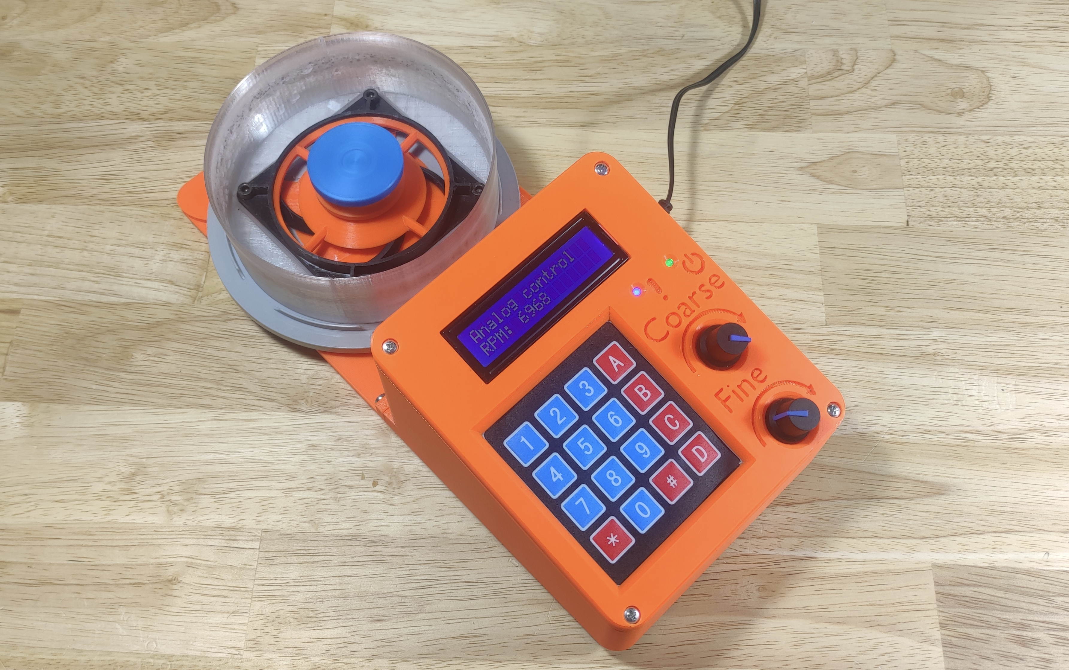
This repository contains the source code for a diy spin coater I designed. A video on YouTube showing some of the design- and build process of this device can be found here.
A spin coater is a tool used for depositing thin films of liquids onto a substrate. Usually the liquid is a solution of a relatively quickly evaporating solvent and the coating solute. The phantom force of centrifugal force causes any liquids to travel radially outwards on the substrate. However, due to surface tension, viscocity and other phenomena, some of the solution sticks to the substrate. The solvent from the thin layer of solution then evaporates, leaving behind a thin film of the solute. Using this technique, it is possible to obtain film thicknesses as small as a couple-dozen nanometers!
So... in a nutshell, a spin coater is essentially just a controllable/programmable spinner onto which one can attach a variety of substrates.
Due to the insane simplicity of this device, one would imagine that such tools would be rather cheap and easy to aquire... However, because usually these devices are used in universities and research laboratories, then unfortunately one can expect a markup in the hundreds, to sometimes thousands of percentage points!!! This is just pure insanity, and because I like building some of my own tools, I decided to design and build my own simple spin coater.
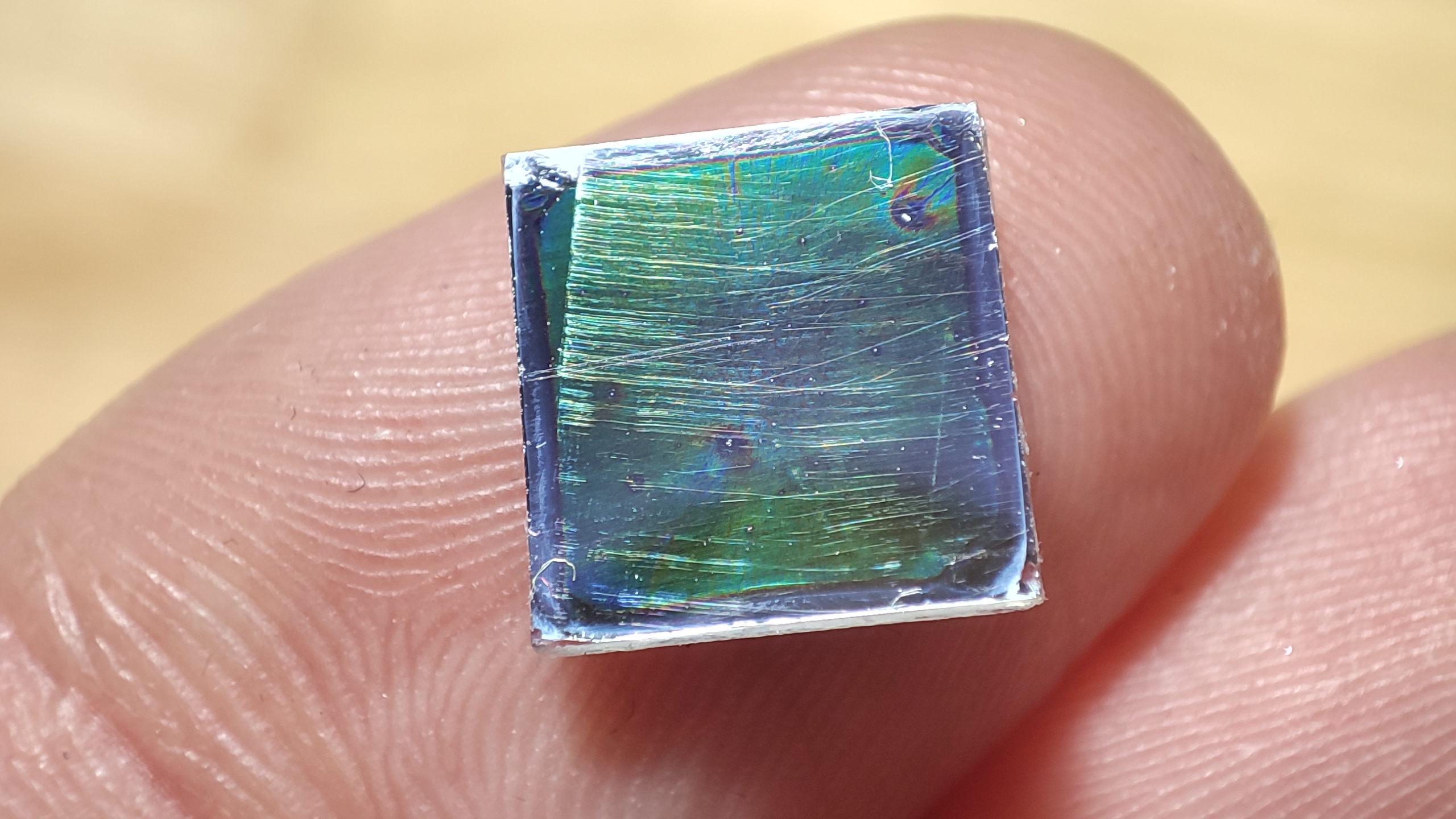
 Above is a photo showing thin-film-interference on a coated first-surface mirror(definitely not optical quality haha). The coating solvent was acetone and solute was acrylic, which is a very challenging mix to work with... hence the somewhat sub-par result.
Don't hold your breath for it! I may upload a few bug fixes if and when they pop up as I work with my spin coater, but I do not intend to improve this version much if at all. There is a likelyhood that a few years from now, I will build a yet more advanced version- a spin coater of laboratory quality for projects that require utmost precision.
The spinner hardware is controlled by a Raspberry-Pi Pico(just Pico from here on), a cheap microcontroller that sits between an Arduino and ESP32 in its processing power. The speed of the Pico as well as its powerful hardware-PWM capabilities are the reason for me picking the Pico for this project.
Multiple extremely important parts of the device, such as the hub and sample holder combo that makes up the gravity chuck design of this spin coater, are meant to be 3d-printed. So, it is basically a necessity to have access to a basic 3d printer... or a cnc mill if going overkill.
Because I did not make a PCB design for the logic board for this project, then you'll also need access to a soldering station.
And of course, a PC of some sort to be able to compile- and upload the firmware onto the Pico. More on software at software setup paragraph of this document.
The list of parts along with their approximate cost can be found at bill of materials section of this document.
This project uses PlatformIO with Visual Studio Code(VSCode) IDE. This near-trivializes certain aspects of programming for the Pico. In addition, this project uses the "earlephilhower" Arduino-pico core (see platformio.ini). For these reasons, as far as I am aware, the code is not possible to compile with any other setup, and even if it is possible, I recommend VSCode with PlatformIO anyways. Because the code uses a couple external libraries that PlatformIO normally manages, then it is necessary to have an Internet connection while dealing with this code.
Getting the firmware for the Pico running should be as simple as these three steps.
- Clone the repository to your desired location and open the project in VSCode.
- Connect the pico to your machine over a usb cable, while holding down the "BOOTSEL" button on the Pico. Release the BOOTSEL button after the Pico is connected.
- Click "Build" and then "Upload" in VSCode, or just "Upload"(this should automatically build the project). The firmware should then be compiled and uploaded to the Pico. Once VSCode signals to you that the upload is complete, simply unplug the USB from the Pico and on the next power-up of the Pico, it should execute the code of the firmware.
Granted that the rest of the surrounding hardware has been built and set up correctly, the spin coater should just simply work. Surrounding hardware specification can be found under the "Hardware design" paragraph of this document.
The prices in the bill of materials are approximate prices of the components that I could quickly find at the time of publishing of this document. These prices are most certainly subject to change over time.
- Anything in brackets is the particular size/component I used.
- Price is for the full amount (eg. 2$ for a component that has 4 stated in the amount, means each component costs 0.50$).
| Amount | Component | Price |
|---|---|---|
| 1 | Raspberry Pi Pico | 5$ |
| 1 | 80mm 4-pin PC fan (Arctic P8 Max) | 10$ |
| 1 | 12V, 1A, power adapter with barrel connector | 5$ |
| 1 | SPI micro-SD-card reader module | 3$ |
| 1 | 16x2 LCD display module | 4$ |
| 1 | 4x4 membrane keypad | 5$ |
| 1 | 15x21mm KCD1 power switch | 1$ |
| 1 | Suitable DC-005 barrel jack (5.5x2.1mm) | 1$ |
| 4 | Suitable anti-slip rubber furniture leg | 2$ |
| 1 | 25x (empty) cd/dvd spindle | 3$/10$ |
| 2 | WH148 10K potentiometer | 2$ |
| 2 | WH148 potentiometer knob | 2$ |
| 2 | PT15 10K potentiometer or equivalent | 0.50$ |
| 12 | 3mm M3 heat set insert | 1$ |
| 4 | 4mm M4 heat set insert | 1$ |
| 2 | TO220 heatsinks | 1$ |
| 16 | M3 10mm screw | 0.50$ |
| 4 | M4 20mm or 17mm screw* | 0.50$ |
| 1 | 12x8cm prototyping/perf board | 0.50$ |
| 1 | 1A glass tube fuse | 0.50$ |
| 1 | glass tube fuse holder | 0.50$ |
| 1 | 1N5819 schottky diode or equivalent | 0.50$ |
| 5 | 1N4005 diode or equivalent | 1$ |
| 2 | 3mm round LED, different colors | 0.50$ |
| 6 | resistors: 1x1K, 1x4K7, 1x6K8, 2x10K, 1x68K | 0.50$ |
| 4 | 100nF ceramic capacitor | 0.50$ |
| 1 | 330nF 15V+ capacitor(I used 1x100nF, 1x100uF) | 0.50$ |
| 2 | 100uF 15V+ electrolytic capacitor | 0.50$ |
| 2 | 2N2222A transistor or equivalent | 0.50$ |
| 1 | F9540N transistor or equivalent | 1$ |
| 1 | L7805CV voltage regulator | 1$ |
| - | Preferred connectors & wiring for soldering | ~5$ |
| - | ~235g of PLA filament | 7$ |
| - | ~42g of PETG filament | 1.50$ |
- Total: ~69$
- Parts with a "*" are technically optional, but recommended. LED-s following a resistor with a * are optional in the same manner.
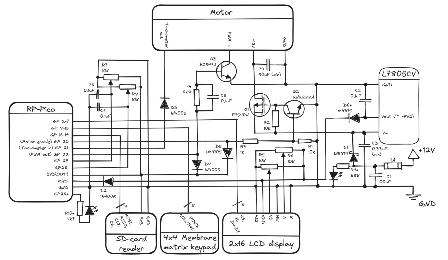
- Q3 transistor in the schematic is a BC547A, however this can be replaced with a 2N2222A or equivalent. BC547A is an old and deprecated NPN BJT. The reason why I used it is to have a slower signal fall time (yes, really), which helps to make the PWM duty-cycle look more like what the Pico outputs. With a 2N2222A transistor, the PWM duty cycle to the fan motor is shorter than what the Pico outputs. Technically it should be fine as the PID control loop should be able to compensate.
- R5 & R6 are PT15 type potentiometers. R7 & R8 are WH148 type potentiometers.
- All 1N4005 diodes could technically be replaced by 1N5819 schottky diodes, but should not be necessary.
- C3 capacity comes from the datasheet for L7805CV, however it does appear that the capacity can be larger. Probably the more important thing is that at least some of the capacity is quick-acting, eg. ceramic capacitors.
Unfortunately, no PCB design exists for this schematic, for I simply used a prototype board and soldered the logic board.
Make sure to install a TO-220 heatsink at least on the L7805CV, it will burn out otherwise. A heatsink on the F9540N is technically not needed, but optional.
One might notice that the 16x2 LCD display is directly interfaced with the Pico, even though the LCD display is running off 5V. This is safe to do as long as RW is tied to ground, guaranteeing that the display only ever gets written to. In such a case, the Pico's 3.3V should be enough to count as a logical high while transmitting data.
If you have built yourself a spin coater of this design and firmware then here's a rundown of what can be found in the menu system of the spinner and what the different options do.
By default the keymapping for the spin coater when using the default 4x4 membrane keypad is as follows:
- Numerics - Correspond to the corresponding number.
*- Backspace / Exit.#- Enter / OK.A- YES, if a question prompt appears; Otherwise the letter A.B- NO, if a question prompt appears; Otherwise the letter B.C- UP, if navigating the menus; Otherwise the letter C.D- DOWN, if navigating the menus; Decimal dot/period (.), if entering a fractional number; Otherwise the letter D.
For a painless first boot of the spin coater, make sure to copy the contents of the "Spinner Memory Image" folder onto a clean SD card. Ideally the SD card has a relatively small memory size.
During booting, the spin coater checks for whether an SD card can be found on the default SPI pins. If not, then the spin coater will enter memoryless operation, and notifies the user of this occuring. The menu should then appear and the spin coater is ready for use in memoryless operation mode.
If the SD card is present, then next the spin coater will check whether a JOBS folder exists in the root directory of the SD card. If not, one will be created automatically. If the JOBS folder exists, then the spin coater will attempt to load any jobs in the folder. The JOBS folder should contain only job files. Job files are extensionless JSON files with a very specific structure. Errors during this phase of booting could end up being unrecoverable AND recurring. If this is the case, the spin coater should be shut down, after which the SD card has to be removed from the spin coater and the files inspected at a PC. Any job files that have been saved incorrectly should be deleted from the folder. The spin coater should be able to boot again after doing so.
Next the spin coater will attempt to locate the PID test job file called PID in the root directory. If this job is not found or is corrupted, then the spin coater will not be able to use the "PID test" functionality. In case of this happening and the user still wanting to use the PID test functionality, the user should shut down the spin coater, then remove the SD card from the spin coater and inspect the files at a PC. If a file called PID exists in the root directory then the integrity of the file should be checked, or alternatively a new PID test job file should replace the corrupted one. If the file is missing then a job has to be created/copied, and the file renamed to PID.
1/5: Quick start1/2: Programmed- Opens up a standard job routine creation dialouge. After the dialouge has been finished, asks whether to run the job or not. If answered affirmatively, then executes the programmed job routine. After the routine has finished, asks whether to run the job again or not. If answered affirmatively, runs the job again. Otherwise asks whether to store the job permanently. If answered affirmatively, then a job name can be entered and the job routine will be saved as a job that can be interacted with through theJobsmenu.2/2: Analog- Gives direct control over the spinner to the user. The speed can be adjusted using the "coarse" and "fine" potentiometers. Coarse control spans from 0% to 90% of maximum spinner speed. Fine control spans a 10% range that gets added ontop of the current coarse control. Eg. if coarse control is set to 38% and fine control to 4%, then the output speed will be 42% of the maximum spinner speed. WARNING: When exiting analog control mode, the spinner spins up to a slow speed for a few seconds, even if the spinner is already stationary!
2/5: Jobs1/3: Load job- Opens a list of jobs currently stored on the SD card. The specific job can be searched in the menu, or by using theSearch for a jobfunction. If the job search turns up positive or the specific job is chosen from the menu, the spin coater asks whether to run the job. If answered affirmatively, performs the job routine.2/3: Create job- First asks to enter the new job routine's name. If a job with the specified name already exists, then offers to enter a different name or delete the job with the specified name. Once a suitable name is chosen, the spin coater asks to confirm the name, after which the standard job routine creation dialouge is opened. After the job routine is finished, the job is saved on the SD card. If the user decided to override a previous job, then the previous job with the same name is deleted before the new job is saved.3/3: Delete job- Opens a list of jobs stored on the SD card. The specific job the user wishes to delete can be searched in the menu, or by using theSearch for a jobfunction. When answered affirmatively to whether to really delete the specified job, the job is removed deleted from the SD card. As it stands right now, the "Search for a job" option is rather buggy, so it is not recommended to use it!
3/5: Test1/2: Spinner params.- Spinner parameters test is a rudimentary test to find out some basic parameters of the spinner. The test consists of a speed- and acceleration tests. The speed test finds out the minimum and maximum speed of the spinner, as well as the minimum duty cycle length to make the spinner spin. The acceleration test tests the maximum acceleration and deceleration three times in a row, and then averages the results. The results from the tests are then displayed to the user to create their job routines accordingly. The minimum duty cycle speed will not be reported to the user but the spin coater's configuration is updated accordingly. Please note that since the very first test is finding out the minimum duty cycle of the spinner, it may look like nothing is happening for a while. Rest assured, the controller is simply creeping up on the minimum duty cycle.2/2: PID- PID test is a rudimentary test to gauge whether the current PID constants are performing acceptably. The routine of this test can be changed by manually replacing the job file namedPIDin the root directory on the SD card.
4/5: Calibration1/6: Set Kp- Displays the currently set P (proportional) constant of the PID controller. If no numeric value is entered, the constant remains unchanged, otherwise new number is set as the new value of the constant. The configuration of the spin coater is also updated so on next "normal operation" boot the constant is retained.2/6: Set Ki- Displays the currently set I (integral) constant of the PID controller. If no numeric value is entered, the constant remains unchanged, otherwise new number is set as the new value of the constant. The configuration of the spin coater is also updated so on next "normal operation" boot the constant is retained.3/6: Set Kd- Displays the currently set D (derivative) constant of the PID controller. If no numeric value is entered, the constant remains unchanged, otherwise new number is set as the new value of the constant. The configuration of the spin coater is also updated so on next "normal operation" boot the constant is retained.4/6: Min duty cycle- Updates the configuration of the spin coater to reflect the new minimum duty cycle value obtained during the last "Spinner parameters" test. Effect is immediate.5/6: Analog-in alpha- Allows for adjusting the alpha of the exponential average for the analog control potentiometer readings. Should be a value between0and1(default is0.01). Smaller values mean the average, and therefore the whole reading of the potentiometers moves slower, but noise in the readings is suppressed. Changing this value is unlikely to be needed.6/6 RPM alpha- Allows for adjusting the alpha of the exponential average for the RPM readings. Should be a value between0and1(default is0.2). Smaller values mean the average, and therefore the whole reading of the potentiometers moves slower, but noise in the readings is suppressed. Changing this value is unlikely to be needed.
5/5: Information1/3: Device info.- Device information contains the current revision of the firmware and hardware, programmer names/handles and hardware developer names/handles, as well as the software- and hardware license identifiers.2/3: HARDWARE LICENSE- Embedded license identifier and link for more information about the Creative Commons 4.0 Attribution-ShareAlike license.3/3: SOFTWARE LICENSE- Embedded MIT license.
In memoryless operation mode the spin coater is not able to execute any functionality that has to do with accessing the memory, naturally.
If Programmed is chosen from first menu option Quick start, then the spin coater will not offer to save the created set of instructions as a job when exiting the Programmed mode.
The second menu option Jobs is completely non-functional.
The "PID test" under third menu option Test is not available.
All spinner configuration will have reverted back to firmware defaults. It is possible to update the configuration, however if the spin coater is shut down, all changes made are lost.
The software of this project is licensed under MIT software license.
The hardware design of this project is licensed under Creative Commons 4.0 Attribution-ShareAlike license.
Under Construction!
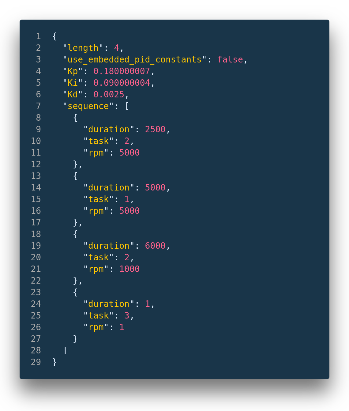
Job files are JSON files with no .json extension.
To have the spin coater load your job files, they need to be placed into the JOBS folder which should be found in the root directory of the SD card. The only exception to this is the job file called PID, which is used for the PID test. The PID job should be found in the root directory of the SD card.
The following is a sample job file.
Under Construction!


