A simple and easy Raspberry Pi Pico powered WSPR, and FT8 beacon system which uses GPS for timing.
Note: The whole project can be assembled on a breadboard (including the ~100mW amplifier) in under an hour - do give it a go!
The whole design is modular, parametric (cost and others), field repairable,
and super extensible. It is almost trivial to add support for more beacon modes.
Note: This documentation is a WIP (work-in-progress), and can't be trusted 100%. Please switch on your brain, and read the actual code and schematics. This repository has more than 10 sub-projects, and can get confusing to follow unless you read the actual code, and schematics.
Use a stable version of the Arduino IDE 1.8.19 or later to build the project.
If you are on Linux, execute the following steps:
sudo apt-get install git  # install 'git' if needed

git clone https://github.com/kholia/Easy-Beacons-STEM.git

make install_arduino_cli
make install_platform
make deps
If you are using Windows OS, execute the following steps:
-
Download this repository.
-
Extract the downloaded zip file to a folder.
-
Run the
setup_arduino_ide.batfile inside this folder.
Note: Change the following lines in the code to use your values:
char message[] = "VU3CER VU3FOE MK68";
char call[] = "VU3FOE";
char loc[] = "MK68";
uint8_t dbm = 27;
- Power from a USB power bank @ 5v.

Note: The PCB version of the Amplified-WSPR-Beacon-v3 sub-project uses the
Pico-Beacons-GPS-v2 firmware (code).
-
Do NOT power with more than 8.4v!
-
Use an 7.5v AC adapter for continuous use
![]()
Note: The PCB version of the Amplified-WSPR-Beacon sub-project uses the Pico-Beacons-GPS-v2 firmware (code).
Note 2: The Amplified-WSPR-Beacon-v2 project uses 5v from USB.
When SW1 switch is OFF, the system acts as a WSPR beacon.
When SW1 switch is ON, the system acts as a FT8 beacon.
TIP: Please use a local (or nearby) receiver to receive and decode the beacon signals! This is important to ensure that your beacon is TX'ing correctly.
Here is the schematic for the Pico-Beacons sketch:
Pin 16 (GP16) is SDA and Pin 17 (GP17) is SCL - connect Si5351 module to these pins. Connect GPS's TX pin to pin 12 (GP9) of Pi Pico.

7W (or less) of HF RF power offers global communications coverage when propagation is good:


WSPR mode demo:

I recommend using a LiFePo4 (LFP) battery which has good energy density and is also priced decently well.

Use the LFP battery with a 1S LFP BMS.

The BMS' output can be connected directly to the 3.3v input of the ESP8266 module.
https://www.waveshare.com/wiki/Solar_Power_Manager - this Solar Power Management Module, for 6V~24V Solar Panel works pretty well.
This will need a HF RF PA in many cases to be usable on the air.
You can also start with the easy-to-build and breadboard-friendly QRPp-Amplifier-v2.

-
Connect a 1k or 2.2k resistor between Si5351 CLK outputs and GND.
-
Connect a series 100nF at Si5351 CLK outputs.
-
Do NOT connect a LED to the output(s) of Si5351 directly. Use a 330 or 470 ohm resistor in series or use a transistor driver at the Si5351 outputs (better).
Please use a LPF at the output.

- mikalhart/TinyGPSPlus#30 (NEO-6M modules can be buggy)
-
1 x 3/5mm LED (purple or pink is recommended)
-
1 x small regular (spst) chassis mount switch
-
1 x 0.25w 470 ohm resistor (CFR / MFR)
-
High quality dupont cables / jumper cables
-
Couple of 100nF 50V MLCC
-
Zero PCB of a suitable size
-
Raspberry Pi Pico board
-
GPS module - NEO-7-M or better
-
BS170 MOSFET (original only)
-
SN74ACT00N (DIP 14 NAND Logic IC)
-
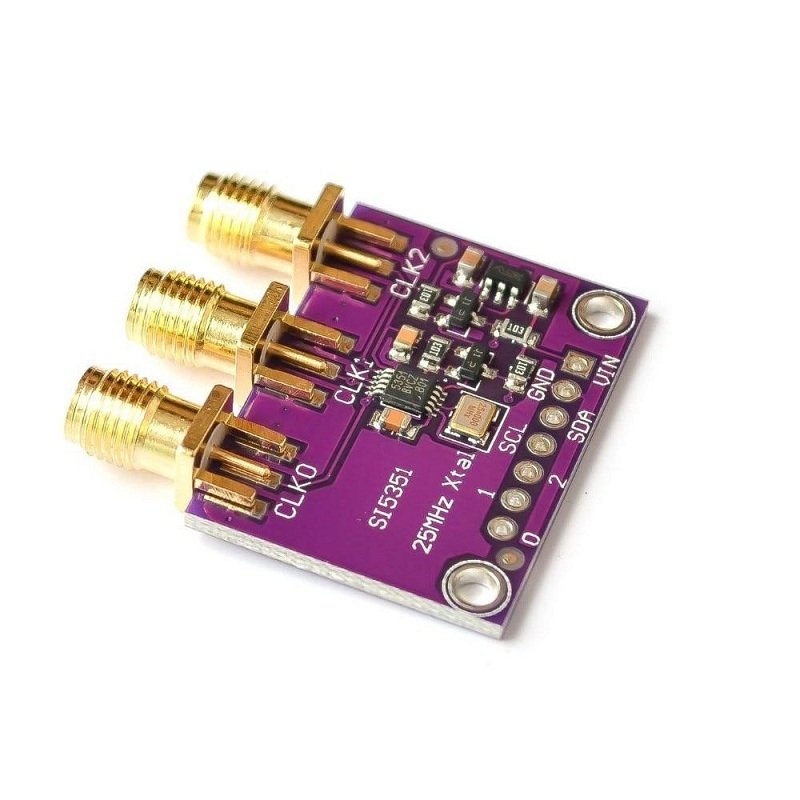
Si5351A Module

-
Hold down the BOOTSEL button on your Pico (keep holding it down) and plug it into your computer's USB port.
Now release the BOOTSEL button.
-
Open Explorer, and open the RPI-RP2 directory like you would any other hard drive.
-
Drag and drop the UF2 file (
firmware.uf2) from this folder into the RPI-RP2 directory. -
Done ;)
Use the latest Arduino IDE along with https://github.com/earlephilhower/arduino-pico to build this source code.
Check out the ADX and PDX radio designs for added fun!