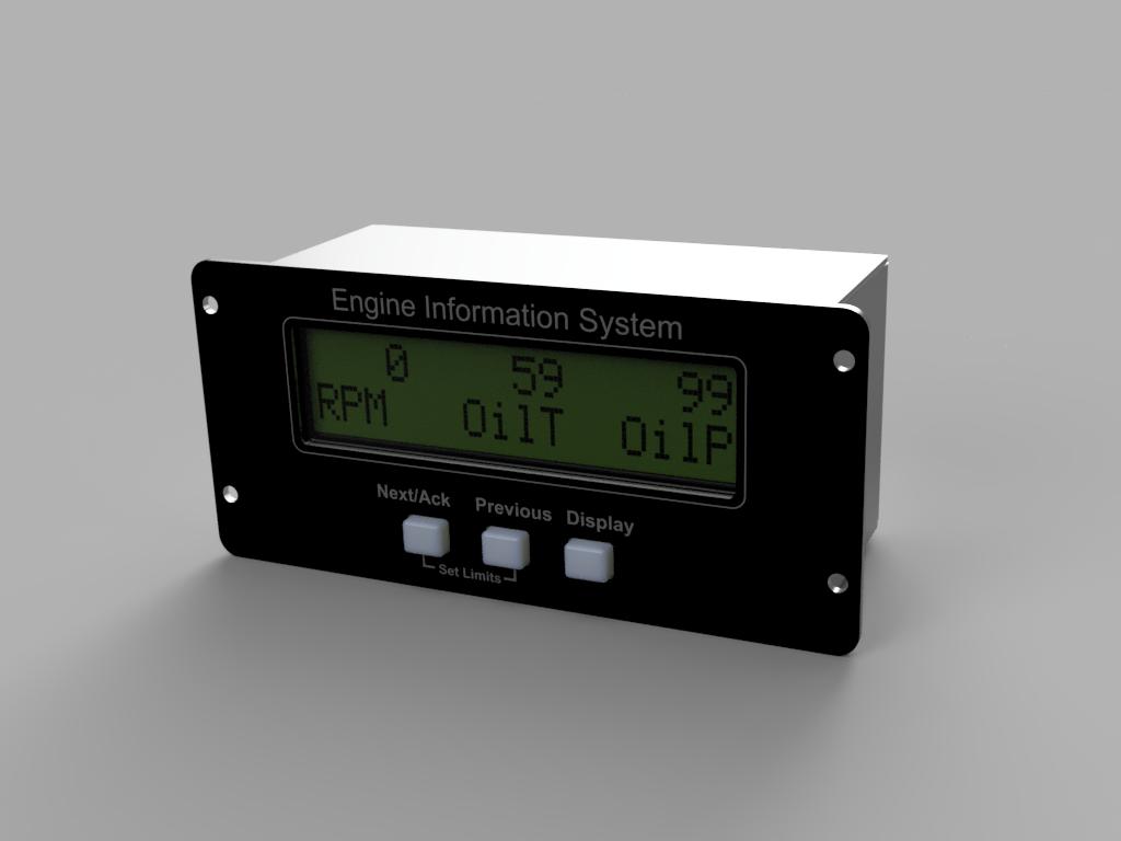
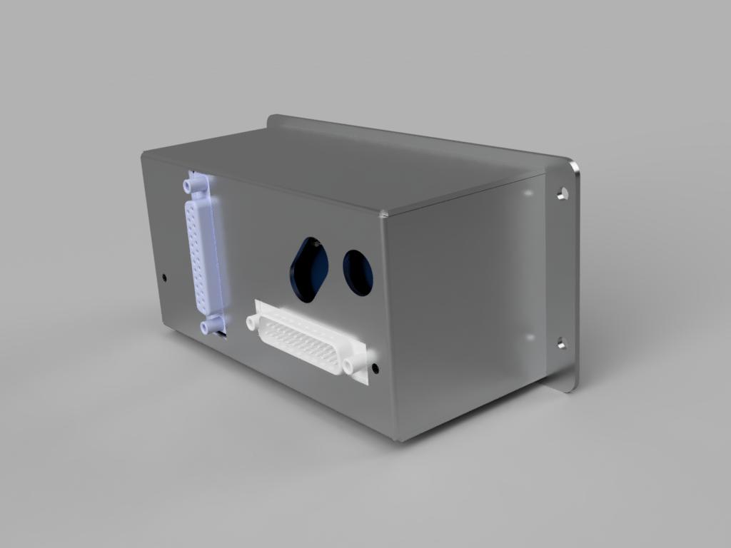
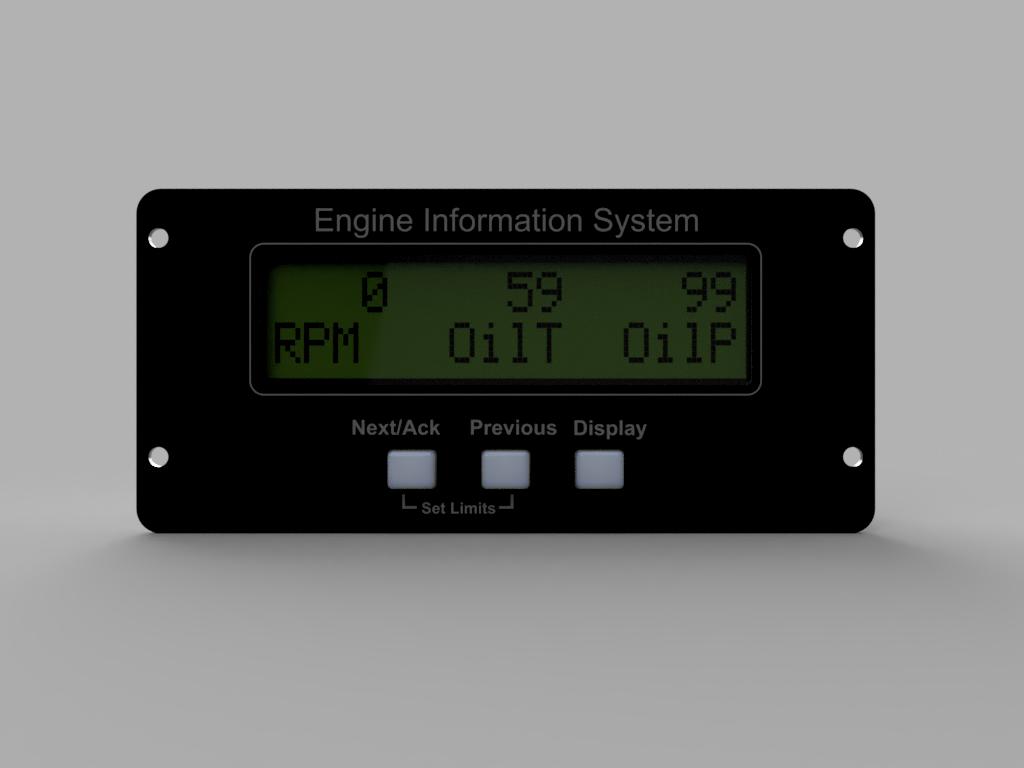
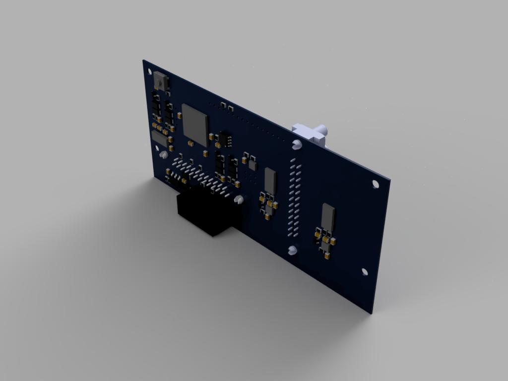
In an effort to bring homebuilt avionics to the experimental aircraft community, I have created a set of plans for a homebuilt aircraft engine monitor. The processor system is based on the same technology found in the Arduino board, allowing the builder to easily add custom firmware. All of the mechanical parts can be sent to hobbyist-friendly fabrication services at reasonable costs or built at home. Since the mechanical dimensions are provided, the builder can also design a custom case.
The features of the engine monitor include:
- EGT (x6)
- CHT (x6)
- Oil Temperature
- Oil Pressure
- Coolant Temperature
- Carb Temperature
- Outside Air Temperature (OAT)
- Tachometer input (x2) (configurable for both inductive and open/collector)
- Fuel flow (x2 for supply/return)
- 6 analog auxiliary inputs
- Flight timer
- Tach time
- Serial data output
- Backlight brightness control
- Warning light with configurable limits
- User definable pages (x4)
- Onboard memory
This repository includes all of the information you need to build the EIS yourself including:
- Schematics
- Mechanical CAD files
- Firmware source code
- Bill of Materials
The cost to buy the components and fabricate the enclosure comes to approximately $250 if you use the recommended vendors.
- Autodesk Fusion 360 (Free Enthusiast license)
- Altium Circuit maker
- Front Panel Designer
- Inkscape
- Atmel Studio
- Waveshare AVR programmer or Atmel ICE programmer (most other programmer options do not work correctly with the ATMega 2560)
- RS-232 to USB converter
- Hakko soldering iron
- Sparkfun hot air gun
- AMScope
- Soldering vise + base
- Multimeter
- Tweezers
- Solder
- Solder wick
- Flux
- Front panel express (CNC and digital printing)
- Par-metal (Sheet metal work)
- Shapeways (3D printing)
- Digikey (Electronic components)
- Modify the faceplate graphic as desired and then order all of the parts listed above
- When the buttons and button guide arrive, they will require some cleanup. This can be done by sanding the edges where they touch the button guide or by forcing them into the button guide and then repeatedly cycling them back and forth.
- Assemble the PCB. I would highly recommend doing this in stages and verifying functionality after each stage.
- Power supply circuit (verify power LED turns on)
- ATMega2560 circuit (verify that Atmel Studio can query the ATMega's ID)
- Warning light (verify that the ATMega can toggle the warning light)
- DSub connectors
- RS-232 circuit (verify that the ATMega can send data to a computer)
- FRAM circuit (verify that the flash IC info can be queried)
- ADC circuit (verify that the ADC correctly reads the input voltage)
- Amplifier/multiplexer circuit (verify that the ADC measures different values when the multiplexer is changed)
- Tach/fuel flow circuits (verify that an interrupt is triggered when a voltage is applied to the tach pins)
- Button board (verify that the ATMega can read each button)
- LCD Screen (verify that the ATMega can print to the display)
- Assemble the button PCB
- Program the ATMega with the EIS firmware
- Place the button guide and buttons in place on the front panel. Place the button PCB on top and use two 4-40 locknuts to secure it in place
- Attach the LCD to the front panel using four 4-40 by 1.5" standoffs threaded on one side.
- Place the engine monitor board on top of the standoffs and secure with two 4-40 by 7/32 standoffs on the bottom and two 4-40 screw on the top.
- Place the rear enclosure over the top (it should be a snug fit). Secure using two 4-40 screws.


