Hugo-ESP8266
Welcome to official git rep for Hugo, universal wifi remote.
UPDATES
RELEASE 1.3 MQTT (24/8/2019):
- Significant MQTT firmware update, it's now fully compatible with home assistant incl. auto discovery
RELEASE 1.3 (14/7/2019):
- Button combinations added, that means 3 additional "virtual" buttons to use.
- MQTT firmware added
Useful links
3D printable case available here:
https://www.thingiverse.com/thing:3641618
Need another Hugo? Get it here:
https://www.tindie.com/products/mcer12/hugo-esp8266-4-button-wifi-remote/
If you use diyHue emulator, just head to Firmwares directory for diyHueTapSwitch sketch!
diyHue github: https://github.com/diyhue/diyHue
Readme
First run
- Push any of the buttons. Led indicator will start blinking and new wifi access point will appear for 5 minutes.
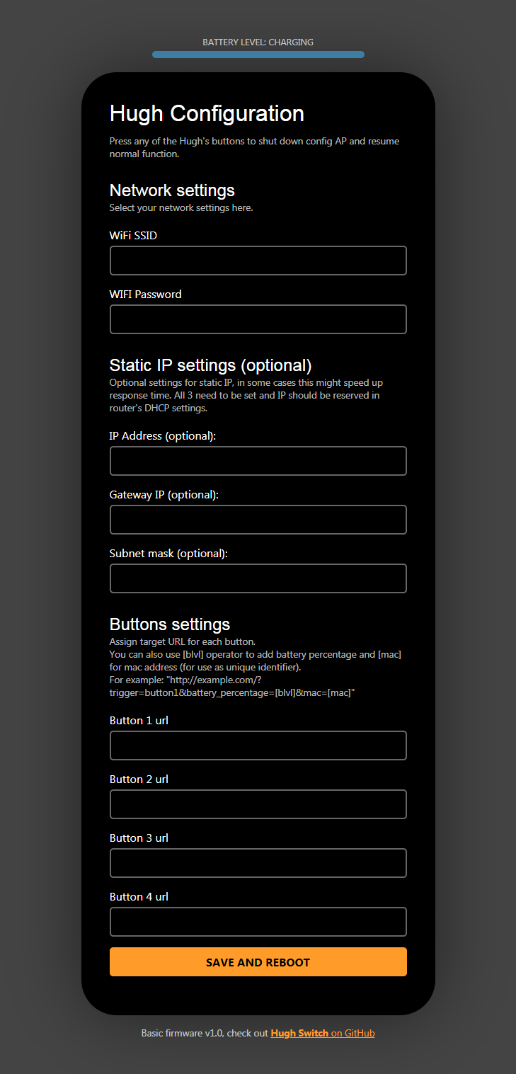
- Connect to the network with phone or PC and open URL 10.10.10.1
- There you will set your wifi credentials and url address for each button.
- (Optional) To further improve performance and battery life, you can add your router's gateway IP address and also pick a static IP for your remote. You will also have to set the static IP on your router.
- (diyHue sketch only) Push and hold buttons 1 and 3 until the led lights up, and release. This will register the remote in diyHue and it will pop up in Hue app.
Changing settings
- Push and hold button 1 and 4 until the led starts blinking and release. Configuration access point will show up for 5 minutes.
- To exit configuration portal, either save changes or press any of the buttons.
Flashing custom FW
You can flash your own Arduino sketch or pick one in this project's Firmwares directory. This guide assumes you have experience with flashing esp8266 and Arduino IDE.
A) USB
- Connect the device to your PC via microUSB connector
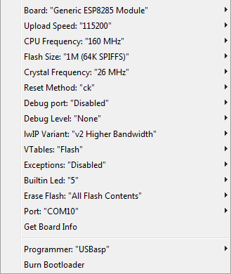
- Choose appropriate COM port in arduino IDE and select correct settings as shown in image below (pay attention to Flash size and reset method settings).
- Upload the sketch. The integrated CH340 chip should handle up to 921600 baud but if you're having issues, lower the baud rate to 115200
NOTE: If the device doesnt show up in available ports, you probably don't have CH340 driver installed
B) Arduino OTA
NOTE: For OTA, you need to first set your wifi credentials in Hugh's config portal.
- If you have Arduino IDE open, close it.
- Push buttons 1 and 3 at the same time and hold them until the led starts blinking fast and release. OTA will now be available for 5 minutes.
- Open arduino IDE and in available ports list there should be your remote.
- Upload your sketch as usual
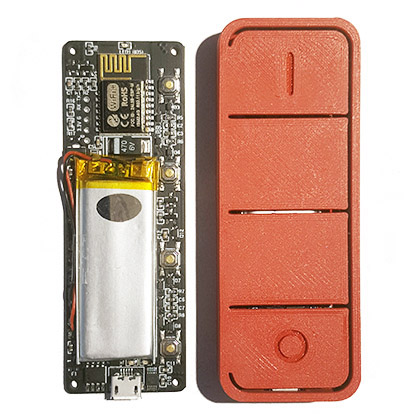
C) SERIAL BREAKOUT
Once you open up the enclosure, you will find the usual breakout pins for ESP8266: VCC, GND, RX, TX, GPIO0. You can solder a header to them but it won't fit in the enclosure anymore so I advise to solder the wires directly if you decide to go with this option.
IMPORTANT: Do NOT connect VCC to external power source!
Battery management
The device has built-in battery sensing, using high resistance voltage divider. You can check current battery level in config AP. You can also send battery percentage with button press (you can set this in config AP). Just keep in mind that the percentage is just a rough estimation and is non-linear. So if you're at 20% it might be a good idea to recharge even though it should be OK for another month or more.
- Voltage below 3.5V is interpreded as 0%.
- Battery protection cuts power at 2.9V, if you drain battery completely.
Useful information for making custom sketch
- You need to set GPIO16 low at the beginning of setup() if you want to use buttons in your sketch. Otherwise anytime you push any button, Hugh will restart.
pinMode(16, OUTPUT);
digitalWrite(16, LOW); - All available ESP8266 GPIOs are used here. You can theoretically use RX, TX and GPIO0 for your own purpose, keep in mind that using RX and GPIO0 will prevent the device from booting up so you need to boot first before connecting anything to these pins. TX should be safe but it's not recommended. If you really need a GPIO, you can solder GPIO5 (connected to status LED).
- This is NOT IR remote, but with skilled soldering, you can replace status LED (GPIO5) with side-positioned smd IR LED. The functional range of such IR blaster is questionable but status led is positioned rather conveniently for that.
CREDITS
Marius Motea and his diyHue project (https://github.com/diyhue/diyHue). His project was the reason to design the remote in the first place and firmware sketch was initially based on it.
Gon for providing his MQTT sketch.