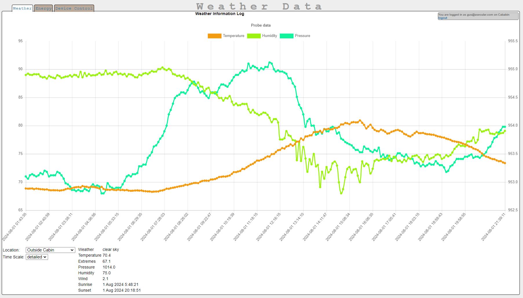
If you want complete control of all the code of a robust multi-user/multi-tenant remote-control, automation and weather data logging system, you might be interested in this system. I developed it to more efficiently use solar energy at my off-grid Adirondack cabin while also keeping the internet accessible and the pipes from freezing. This started out as a simple multi-probe weather monitoring system (ESP8266 MicroWeather) to which I added first reliability automation (Hotspot-Watchdog), then remote control, then solar inverter monitoring, then home automation, and finally a multi-tenant security model.
There's also a page to show data from your solar inverter if you happen to be using the one I know about (SolArk):
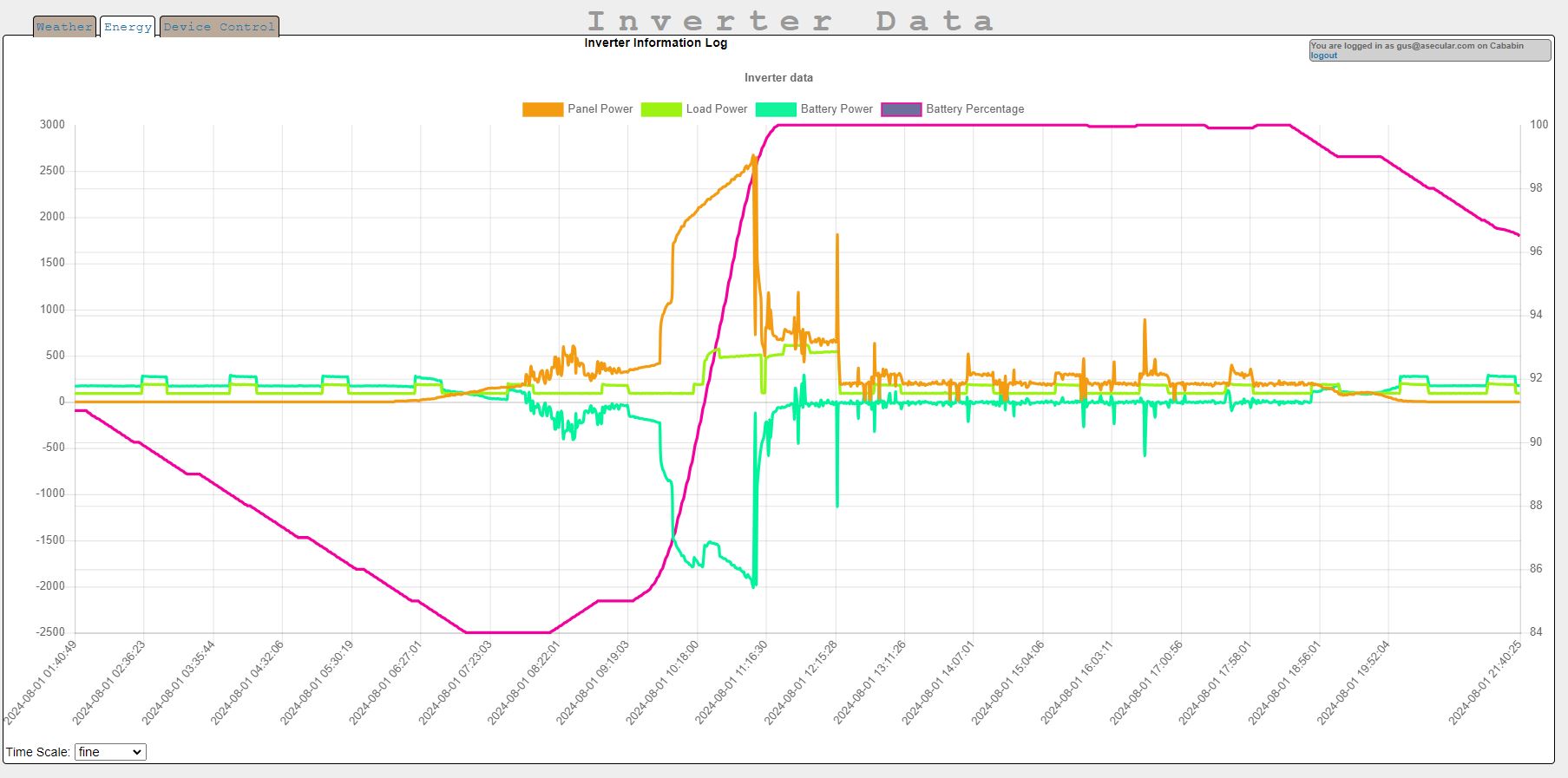
But the main feature in this system is that it allows you to remotely control devices across the internet and also supports automation based on the values of sensors known to the central database. It does this using a server running PHP/MySQL. There are relatively few dependencies: PHP, MySQL, cURL, and the Chart.js graphing library, so this is not much of a headache to get working on just about any server where you have a modest amount of control.
A web-based tool (tool.php) allows you to edit the value column of a table called device_feature, where device_id is equal to device_id specified in config.c on the Arduino-compiled code (remote.ino, config.h, config.c, and index.h) uploaded to your ESP8266 device. Once installed on the ESP8266, it regularly polls the server (make sure to set hostGet in config.c before compiling) to look for information in those device_feature records, and it automatically copies data from the value column to the pins they're connected to (which is specified in device_type_feature). These pins can then be used to turn on relays, which allow you to turn on large loads in remote locations. I'm using this system to remotely turn on the boiler, hot water heater, a 240 volt EV outlet, and three different 120 volt outlets connected to electric space heaters in my off-grid cabin.
Device_features can also be sensors reachable by a GPIO pin or I2C, and if multiple sensors are attached to an ESP8266, the additional ones are all identified by device_feature_id.
One caveat: this system is one where the server tells the microcontroller what pins do what and can change assignments without a need to reflash or even restart the microcontroller. For some pins (notably GPIO10 and GPIO9 on an ESP8266, which are used for accessing on-board flash storage), setting them to outputs and forcing them to take a value will cause the ESP8266 to crash and restart. So definitely test all your pin control arrangements while local to the ESP8266 before using it remotely.
To expand the number of pins usable for remote control, you can add one or more slave Arduinos running my slave software (be sure to give them all different I2C addresses): https://github.com/judasgutenberg/Generic_Arduino_I2C_Slave and just add the I2C address of the slave Arduino to the device_type_feature record.
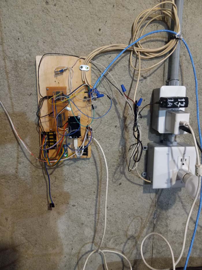
Some of the code (remote.ino, config.h, config.c, and index.h) is designed to be compiled in the Arduino environment and uploaded to an ESP8266. (I used a NodeMCU, which is cheap and physically easy to work with.) The rest of the code needs to be placed on a server that can process PHP pages and communicate with a MySQL database. (It's not a pretty language, but I like PHP because it runs pretty well and doesn't require compilation or setup headaches on most servers or Raspberry Pis.)
To get this installed, first create an initial database by running remote_control.sql on the server and then change config.php so the PHP will know how to connect to the database. You then create a tenant and a user connected to that tenant via tenant_user and give that tenant a storage_password so that the ESP8266 will be able to authenticate communication with the backend. This storage password is then set as storage_password (along with other important config information like your WiFi credentials and the domain and path where your backend is hosted) in config.c before compiling the Arduino code and uploading it to an ESP8266. Then you create a device and give it device_features, and set the device_id of the ESP8266 to the device_id of that device in config.c so that the backend will know what ESP8266 is polling to either log sensor data or pick up remote control settings and additional sensors.
Now you need to create a new account with the web front end. The first user in the database is automatically given the role of super, which can edit the user table, create reports, and administer other tenants in the database, among other priviledges. That user also automatically gets a tenant, connected to the user via the tenant_user table. Superusers can manage the connection of tenants to users via the user or tenant editors. Users who need tenants can either ask the superuser to connect them to their tenant or new users can be invited to join their tenant by using a specially-crafted link (which can be produced by one of the utilities in the Utilities tab).
This is another advancement from my Moxee Hotspot Watchdog system, which was itself an advancement from my ESP8266-Micro-Weather system. This system still logs weather data using a variety of common weather sensors and can, if configured correctly, reboot a Moxee cellular hotspot when it craps out and needs a reboot (which is essential for reliably connecting to my off-grid cabin, which is a major pre-requisite for all the features I am about to describe).
From there, here's an overview of how to set up control for a particular system controlled by a pin on your ESP8266:
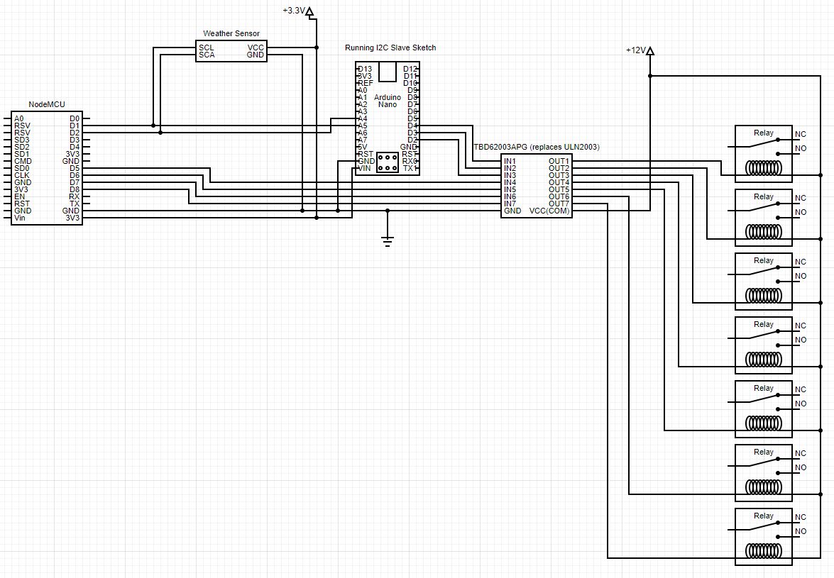
- Connect the system to be turned on or off to the ESP8266 somehow (see schematic for how I connected seven relays). Usually this involves a relay and a relay driver circuit such as the ULN2003 (there are lots of examples of this online, for example https://microcontrollerslab.com/relay-driver-circuit-using-uln2003/).
- Add a record to the device table to represent your particular ESP8266. In the code, device_id and location_id refer to the same entity. Your ESP8266 will send that id as device_id to the server whenever it polls it to get updates on what values the device with its pins should have. You will need to set device_id to this value in config.c before compiling the code for you ESP8266.
- Add a record to the device_type table describing your particular type of device (in this case, ESP8266). Details for this don't matter much.
- Add a record to the device_type_feature table describing the pin (mostly the pin number and, if it is on an Arduino slave, the I2C address).
- Add a record to the device_feature table describing the specific pin (here a human readable name would be useful).
- You can change the state of a particular ESP8266's pin by changing the state of the value column in the device_feature record. Make sure to set enabled to 1 as well. Depending on the speed of your network and how frequently you set polling, the change should manifest within a minute or so.
Here is the user interface, which allows you to turn items on and off in the list by checking the "power on" column. (You do it all from the device_feature list view.)
This system tracks whether or not data makes it to the ESP8266 that it is sent to via the last_known_device_value and last_known_device_modified columns. This is important when a remote control action needs to be verified as having happened. Otherwise you end up looking for a change of temperature or power consumption at your off-grid cabin for such confirmation. I use a string hash table as a very simple database to store this information on the microcontroller, which might be overkill. But the ESP8266 has enough storage and memory to be a little wasteful of resources. Also, every change of state for a device_feature is logged in the device_feature_log table.
In addition to supporting the changing of pin states using a server, this system also implements a local API with two ESP8266-served endpoints (first you have to know its local address, which is being saved in the device table as ip_address). These endpoints are /readLocalData and /writeLocalData. The former gives a JSON object with info about the pins and their current state. The other accepts two querystring params: id and on. id is usually the pin number, unless it's a pin on a slave Arduino, in which case it is [I2C address of slave].[pin number]. On is just a 1 for on and 0 for off. Using that second API, you can turn on circuits directly and then the ESP8266 will update the server with the new value information. This is useful when building a local remote control panel, which was my next development effort.
(see https://github.com/judasgutenberg/Local_Remote)
index.h has the HTML for a locally-served front-end to take advantage of the local API, though the Local Remote is better for this than relying on the massive computational overhead of a modern web browser. It would also be easy to write a phone app, which would be great for someone who always keeps a phone nearby. But I am not such a person.
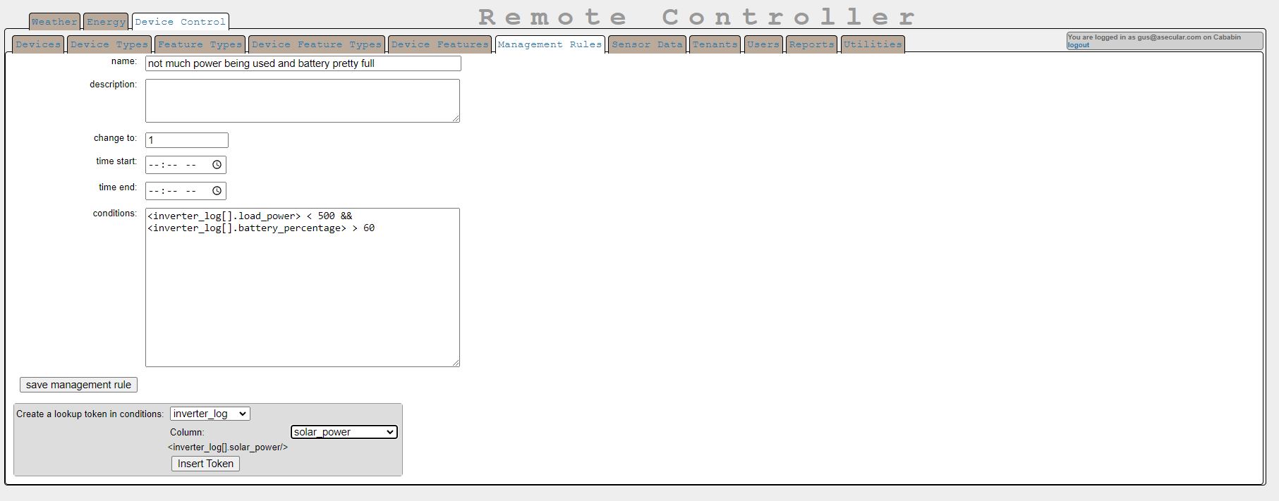
There is also an inverter-related endpoint in data.php to return live inverter information to the local remote (for now, this only works with SolArk inverters, as that is the kind I have, though they are notoriously hard to get data from). This inverter data is also available to a conditions-processing system that automatically turns device_features on or off depending on inverter sensor values. Such conditions go into the table management_rule in the conditions column. Conditions include tokens that take the form <tablename[location_id].columnName>. An example token would be <inverter_log[].battery_percentage>. A condition made with that token would be something like
<inverter_log[].battery_percentage> > 80
which would set the connected device_feature's value to result if the condition is met and allow_automatic_management in the device_feature record is true. Management_rules can be added to device_features in the device_feature editor, which looks like this:
Management_rules can be edited in the management_rule editor, which looks like this:
At the bottom is a tool you can use to automatically construct a value token to place in conditions. Treat these as variables in an expression to be evaluated as true or false. You can use multiple tokens, parentheses, arithmatic operators, and scalar numbers in such expressions.
There is support for reports (currently restricted to superusers), which are defined as a form (using JSON) and SQL. Simple reports can just be SQL, though if you need to send parameters to a report, you will need to define a form. Perhaps forms definitions are best shown by example.
This JSON defines a form with one parameter
  [ {
	    "label": "Which changer",
      "name" :"changerX",
      "type" : "select",
"values": ["changer1", "changer2", "changer3", "changer4", "changer5", "changer6","changer7"]
	}]
the value of which is substituted into the SQL component of the report:
SELECT <changerX/>, battery_percentage, solar_power, load_power, battery_power FROM inverter_log ORDER BY DESC
the "values" parameter in the form JSON can also be a SQL string to generate a list of options from the database. If so, the SQL needs to return a 'text' column for a proper dropdown list of options to be displayed. A log of reports is kept with enough information to allow them to be re-run with the same set of parameters as the original run.
Obviously there is a lot of power in such a system, since, depending on MySQL user permissions, a report-writer might have access to any data on the database server; only fully trusted users should get access to report creation and some reports are too powerful for anyone but admins to run.
