Play music by plucking strings made from laserbeams!
The instrument is composed of two separate components (laser bar and receiver) which are currently designed to be mounted in a 30" door frame. A note is played when one of the eight beams is broken.
- docs - Component and other documentation captured from other sources
- experiments - Mostly test code to figure out how to get things working
- images - Photos and renderings
- models - 3D model files for printable components
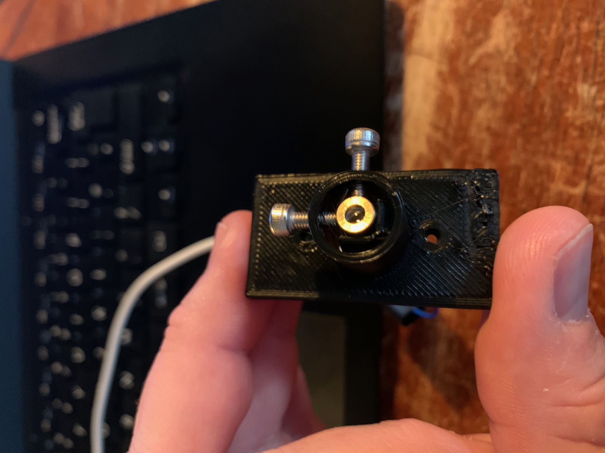
- laser_base.scad - Semi-paramentric laser LED holder with fine aiming adjustment
- firmware.py - Micropython firmware for the ESP32
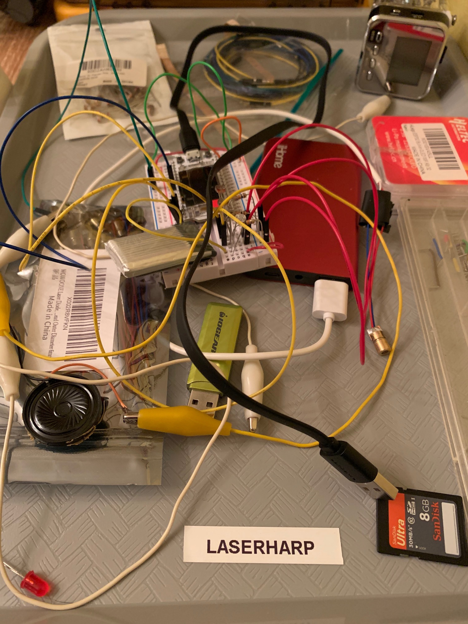
A functional (if not beautiful) prototype of the electronics and firmware has been completed and work is now focused on the physical components.
Once mounts for the lasers and sensors are complete these will be mounted on a full-size test rig to verify operation at full scale and test things like the difficulty of aiming the beams, etc.
8 laser beams (notes c to C) are aimed at 8 photoresisors connected on an ESP32. The ESP32 scans the photoresistors and plays a note if the beam is interrupted.
- 1x Heltec WiFi Kit 32
- 1x 1000 mAh lithium battery
- 8x photoresistors
- 8x 10k resistors
- 1x 8ohm mini speaker
- 8x 5v ???mw red laser diodes
The ESP32 provides all the required functionality and the possibility for a wireless instrument interface in the future. The Heltec board was selected because of its low-cost, compact construction and inclusion of a robust power supply (typically a weak point of most ESP32 designs).
TODO: add schematic
The photoresistors are connected to GPIO 32 through 39 using a voltage divider. The speaker is simply connected between GPIO 14 and ground.
The current version of the firmware scans each photoresistor once per second and when dark, plays the according note via PWM to a small speaker attached to pin 14.
This completes the proof-of-concept stage so construction of the chassis using the selected components can begin. The basic PWM "beeper" may be replaced with an amplified speaker or possibly an external WiFi/Bluetooth instrument connection.

