This library directly interfaces Arduino and esp8266 microcontrollers to DSC PowerSeries security systems for integration with home automation, notifications on alarm events, and usage as a virtual keypad. This enables homes and offices with existing DSC security systems (of which millions have been installed over the decades) to connect with modern devices and software, while retaining the features and reliability of a hardwired system for under $5USD in components.
The built-in examples can be used as-is or as a base to adapt to other uses:
- Home automation: Home Assistant, Apple HomeKit & Siri, Athom Homey
- Notifications: PushBullet, Twilio SMS, MQTT, E-mail
- Virtual keypad: Web interface, Blynk mobile app
-
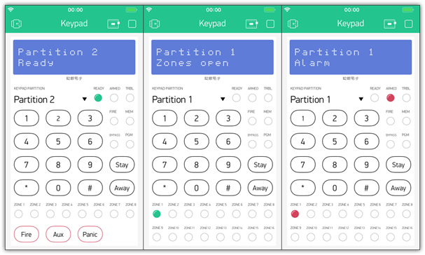
Blynk app virtual keypad:
-
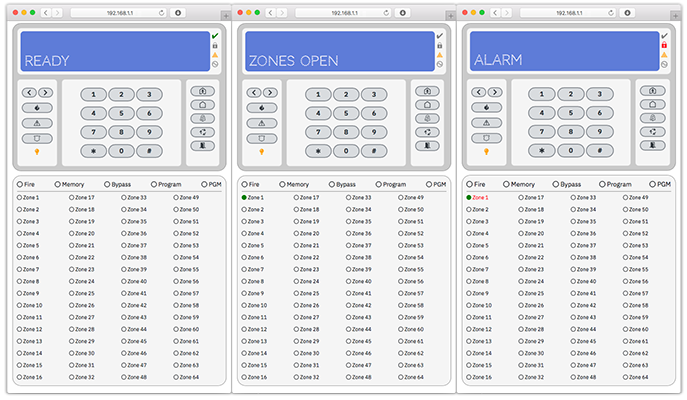
Web virtual keypad:


I Had: A DSC security system not being monitored by a third-party service.
I Wanted: Notification if the alarm triggered.
I was interested in finding a solution that directly accessed the pair of data lines that DSC uses for their proprietary Keybus protocol to send data between the panel and modules (keypads, etc). Tapping into the data lines is an ideal task for a microcontroller and also presented an opportunity to work with the Arduino platform.
While there has been excellent discussion about the DSC Keybus protocol and a few existing projects, there were major issues that remained unsolved:
- Error-prone Keybus data capture.
- Limited data decoding - there was good progress for armed/disarmed states and partial zone status for a single partition, but otherwise most of the data was undecoded (notably missing the alarm triggered state).
- Read-only - unable to control the Keybus to act as a virtual keypad.
- No implementations to do useful work with the data.
Poking around with a logic analyzer and oscilloscope revealed that the errors capturing the Keybus data were timing issues. Updating the existing projects to fix this turned out to be more troublesome than starting from scratch, so this project was born. After resolving the data errors, it was possible to reverse engineer the protocol by capturing the Keybus binary data as the security system handled various events. At this point, this interface resolves all of the earlier issues (and goes beyond my initial goal of simply seeing if the alarm is triggered).
- Monitor the alarm state of all partitions: alarm triggered, armed/disarmed, entry/exit delay, fire triggered, keypad panic keys
- Monitor the state of all zones: zones open/closed, zones in alarm
- Monitor the system status: trouble, AC power, battery
- Virtual keypad: Send keys to the panel for any partition
- Direct Keybus interface: does not require the DSC IT-100 serial interface.
- Supported security systems: DSC PowerSeries
- Verified panels: PC585, PC1555MX, PC1565, PC5005, PC5015, PC1616, PC1808, PC1832, PC1864.
- All PowerSeries series are supported, please post an issue if you have a different panel (PC5020, etc) and have tested the interface to update this list.
- Rebranded DSC PowerSeries (such as some ADT systems) should also work with this interface.
- Supported microcontrollers:
- Arduino: Uno, Mega, Leonardo, Mini, Micro, Nano, Pro, Pro Mini (ATmega328P, ATmega2560, and ATmega32U4-based boards at 16Mhz)
- esp8266: NodeMCU v2 or v3, Wemos D1 Mini, etc.
- Includes Arduino framework support, integrated WiFi, and improved specs at only $3USD shipped.
- NodeMCU modules are a good choice as they can be powered directly from the DSC panel, the Wemos D1 Mini requires an additional 5v voltage regulator to handle the 12v+ DSC panel power.
- Designed for reliable data decoding and performance:
- Pin change and timer interrupts for accurate data capture timing
- Data buffering: helps prevent lost Keybus data if the sketch is busy
- Extensive data decoding: the majority of Keybus data as seen in the DSC IT-100 Data Interface developer's guide has been reverse engineered and documented in
src/dscKeybusPrintData.cpp. - Non-blocking code: Allows sketches to run as quickly as possible without using
delayordelayMicroseconds
- Unsupported security systems:
- DSC Classic series (PC1500, etc) use a different data protocol, though support is possible.
- DSC Neo series use a higher speed encrypted data protocol (Corbus) that is not possible to support.
- Honeywell, Ademco, and other brands (that are not rebranded DSC systems) use different protocols and are not supported.
- Potential future features (pending sufficient interest):
- Virtual zone expander: Add new zones to the DSC panel emulated by the microcontroller based on GPIO pin states or software-based states. Requires decoding the DSC PC5108 zone expander data.
- Installer code unlocking: Requires brute force checking all possible codes and a workaround if keypad lockout is enabled (possibly automatically power-cycling the panel with a relay to skip the lockout time).
- ESP32 microcontroller support: At minimum, requires changing the timer interrupts.
- DSC Classic series support: This protocol is already decoded, use with this library would require major changes.
- 1.2
- New: Virtual keypad web interface example, thanks to Elektrik1 for this contribution!
- As of esp8266 Arduino Core 2.5.1, you may need to manually update the esp8266FS plugin for SPIFFS upload.
- New: Support esp8266 CPU running at 160MHz - this helps sketches using TLS through BearSSL
- Updated: HomeAssistant-MQTT example includes availability status, thanks to bjrolfe for this contribution!
- Updated: List of tested DSC panels: PC585, PC1565, PC5005, PC1808
- Updated: esp8266 power wiring diagrams
- Updated: esp8266 module list
- New: Virtual keypad web interface example, thanks to Elektrik1 for this contribution!
- 1.1
- 1.0
- New: Blynk virtual keypad example sketch and app layout examples
- New: Virtual keypad support for PGM terminals 1-4 command output
- New: Status
dsc.keybusConnectedto check if data is being received from the DSC panel - New: Auxiliary input alarm decoding
- 0.4
- New: Virtual keypad support for partitions 3-8, thanks to jvitkauskas for contributing the necessary logs
- New: Support ATmega32U4-based Arduino boards (switched to AVR Timer1)
- Changed: Simplified example names, configurations, added version numbers
- Bugfix: Virtual keypad writes with partitions 5-8 enabled
- Bugfix: F/A/P alarm key writes with
processModuleDatadisabled - Bugfix: HomeAssistant example
configuration.yamlerror foralarm_control_panel
- 0.3
- New: Status for partitions 2-8, zones 33-64
- New: Virtual keypad support for partition 2
- New: Athom Homey integration example sketch, thanks to MagnusPer for this contribution!
- New: PCB layouts, contributed by sjlouw
- New: Configurable number of partitions and zones to customize memory usage:
dscPartitionsanddscZonesindscKeybusInterface.h - New: KeybusReader decoding of commands
0xE6and0xEB - Changed: Split examples by platform
- Changed: Arduino sketches no longer use pin 4 to avoid a conflict with the SD card on Ethernet shields.
- Changed: MQTT examples updated with username and password fields
- Changed:
processRedundantDatanow true by default to prevent storing repetitive data, reduces memory usage. - Note: This release changes the library methods to accommodate multiple partitions, existing sketches will need to be updated to match the new example sketches.
- 0.2
- New: Status for zones 9-32
- New: Home Assistant integration example sketch
- New: Panel data buffering, adds
dscBufferSizetodscKeybusInterface.hto allow configuration of how many panel commands are buffered to customize memory usage (uses 18 bytes of memory per command buffered).
- 0.1 - Initial release
- Arduino IDE: Search for
DSCin the Library Manager -Sketch > Include Library > Manage Libraries
- PlatformIO IDE: Search for
DSCin the PlatformIO Library Registry
- PlatformIO CLI:
platformio lib install "dscKeybusInterface" - Alternatively,
git cloneor download the repo .zip to the Arduino/PlatformIO library directory to keep track of the latest changes.
The included examples demonstrate how to use the library and can be used as-is or adapted to integrate with other software. Post an issue/pull request if you've developed (and would like to share) a sketch/integration that others can use.
-
Status: Processes and prints the security system status to a serial interface, including reading from serial for the virtual keypad. This demonstrates how to determine if the security system status has changed, what has changed, and how to take action based on those changes. Post an issue/pull request if you have a use for additional system states - for now, only a subset of all decoded commands are being tracked for status to limit memory usage:
- Partitions armed away/stay/disarmed
- Partitions in alarm
- Partitions exit delay in progress
- Partitions entry delay in progress
- Partitions fire alarm
- Zones open/closed
- Zones in alarm
- Keypad fire/auxiliary/panic alarm
- Panel AC power
- Panel battery
- Panel trouble
- Keybus connected
-
Homebridge-MQTT: Integrates with Apple HomeKit, including the iOS Home app and Siri. This uses MQTT to interface with Homebridge and homebridge-mqttthing and demonstrates using the armed and alarm states for the HomeKit securitySystem object, zone states for the contactSensor objects, and fire alarm states for the smokeSensor object.
-
HomeAssistant-MQTT: Integrates with Home Assistant via MQTT. This uses the armed and alarm states for the HomeAssistant Alarm Control Panel component, as well as zone, fire alarm, and trouble states for the Binary Sensor component.
-
Homey: Integrates with Athom Homey and the Homeyduino library, including armed, alarm, and fire states (currently limited to one partition), and zone states. Thanks to MagnusPer for contributing this example!
-
Pushbullet (esp8266-only): Demonstrates how to send a push notification when the status has changed. This example sends notifications via Pushbullet and requires the esp8266 for SSL support.
-
Twilio (esp8266-only): Demonstrates how to send a push notification when the status has changed. This example sends notifications via Twilio and requires the esp8266 for SSL support - thanks to ColingNG for contributing this example!
-
Email (esp8266-only): Demonstrates how to send an email when the status has changed. Email is sent using SMTPS (port 465) with SSL for encryption - this is necessary on the ESP8266 until STARTTLS can be supported. For example, this will work with Gmail after changing the account settings to allow less secure apps.
This can be used to send SMS messages if the number's service provider has an email to SMS gateway - examples for the US:
- T-mobile: 5558675309@tmomail.net
- Verizon: 5558675309@vtext.com
- Sprint: 5558675309@messaging.sprintpcs.com
- AT&T: 5558675309@txt.att.net
-
VirtualKeypad-Blynk (esp8266-only): Provides a virtual keypad interface for the free Blynk app on iOS and Android. Scan one of the following QR codes from within the Blynk app for an example keypad layout:
Note: Installing Blynk as a local server is recommended to keep control of the security system internal to your network. This also lets you use as many widgets as needed for free - local servers can setup users with any amount of Blynk Energy. Using the default Blynk cloud service with the above example layouts requires more of Blynk's Energy units than available on the free usage tier.
-
VirtualKeypad-Web (esp8266-only): Provides a virtual keypad web interface, using the esp8266 itself as a standalone web server. This example uses the ESP Async Web Server and Websockets - thanks to Elektrik1 for contributing this example!
-
KeybusReader: Decodes and prints data from the Keybus to a serial interface, including reading from serial for the virtual keypad. This can be used to help decode the Keybus protocol and is also handy as a troubleshooting tool to verify that data is displayed without errors.
See
src/dscKeybusPrintData.cppfor all currently known Keybus protocol commands and messages. Issues and pull requests with additions/corrections are welcome!
DSC Aux(+) ---+--- Arduino Vin pin
              |
              +--- esp8266 NodeMCU Vin pin
              |
              +--- 5v voltage regulator --- esp8266 Wemos D1 Mini 5v pin

DSC Aux(-) --- Arduino/esp8266 Ground

                                   +--- dscClockPin (Arduino Uno: 2,3 / esp8266: D1,D2,D8)
DSC Yellow --- 15k ohm resistor ---|
                                   +--- 10k ohm resistor --- Ground

                                   +--- dscReadPin (Arduino Uno: 2-12 / esp8266: D1,D2,D8)
DSC Green ---- 15k ohm resistor ---|
                                   +--- 10k ohm resistor --- Ground

Virtual keypad (optional):
DSC Green ---- NPN collector --\
                                |-- NPN base --- 1k ohm resistor --- dscWritePin (Arduino Uno: 2-12 / esp8266: D1,D2,D8)
      Ground --- NPN emitter --/
- The DSC Keybus operates at ~12.6v, a pair of resistors per data line will bring this down to an appropriate voltage for both Arduino and esp8266.
- Arduino: connect the DSC Yellow (Clock) line to a hardware interrupt pin - for the Uno, these are pins 2 and 3. The DSC Green (Data) line can be connected to any of the remaining digital pins 2-12.
- esp8266: connect the DSC lines to GPIO pins that are normally low to avoid putting spurious data on the Keybus: D1 (GPIO5), D2 (GPIO4) and D8 (GPIO15).
- Virtual keypad uses an NPN transistor and a resistor to write to the Keybus. Most small signal NPN transistors should be suitable, for example:
- 2N3904
- BC547, BC548, BC549
- That random NPN at the bottom of your parts bin (my choice)
- Connections should be soldered, breadboards can cause issues.
This allows a sketch to send keys to the DSC panel to emulate the physical DSC keypads and enables full control of the panel from the sketch or other software.
Keys are sent to partition 1 by default and can be changed to a different partition. The following keys can be sent to the panel - see the examples for usage:
- Keypad:
0-9 * # - Arm stay (requires access code if quick arm is disabled):
s - Arm away (requires access code if quick arm is disabled):
w - Arm with no entry delay (requires access code):
n - Fire alarm:
f - Auxiliary alarm:
a - Panic alarm:
p - Door chime enable/disable:
c - Reset:
r - Exit:
x - Change partition:
/+partition numberor setwritePartitionto the partition number. Examples:- Switch to partition 2 and send keys:
/2+1234 - Switch back to partition 1:
/1 - Set directly in sketch:
dsc.writePartition = 8;
- Switch to partition 2 and send keys:
- Command output 1:
[ - Command output 2:
] - Command output 3:
{ - Command output 4:
}
Panel options affecting this interface, configured by *8 + installer code - see the DSC installation manual for your panel for configuration steps:
- PC1555MX/5015 section 370, PC1616/PC1832/PC1864 section 377:
-
Swinger shutdown: By default, the panel will limit the number of alarm commands sent in a single armed cycle to 3 - for example, a zone alarm being triggered multiple times will stop reporting after 3 alerts. This is to avoid sending alerts repeatedly to a third-party monitoring service, and also affects this interface. As I do not use a monitoring service, I disable swinger shutdown by setting this to
000. -
AC power failure reporting delay: The default delay is 30 minutes and can be set to 000 to immediately report a power failure.
-
-
Memory usage can be adjusted based on the number of partitions, zones, and data buffer size specified in
src/dscKeybusInterface.h. Default settings:- Arduino: up to 4 partitions, 32 zones, 10 buffered commands
- esp8266: up to 8 partitions, 64 zones, 50 buffered commands
-
PCB layouts are available in
extras/PCB Layouts- thanks to sjlouw for contributing these designs! -
Support for the esp32 and other platforms depends on adjusting the code to use their platform-specific timers. In addition to hardware interrupts to capture the DSC clock, this library uses platform-specific timer interrupts to capture the DSC data line in a non-blocking way 250us after the clock changes (without using
delayMicroseconds()). This is necessary because the clock and data are asynchronous - I've observed keypad data delayed up to 160us after the clock falls.
AVR Freaks - DSC Keybus Protocol: An excellent discussion on how data is sent on the Keybus.
stagf15/DSC_Panel: A library that nearly works for the PC1555MX but had timing and data errors. Writing this library from scratch was primarily a programming exercise, otherwise it should be possible to patch the DSC_Panel library.
dougkpowers/pc1550-interface: An interface for the DSC Classic series.