This course has a mixed bag of example projects for the IoT-Avans-Course. The course starts with a relatively simple introduction with different programming exercises. The Espressif ESP32 Dev Module has been used for the different exercises.
All exercises have been programmed in Visual Studio Code with the PlatformIO plugin.
Project Overview
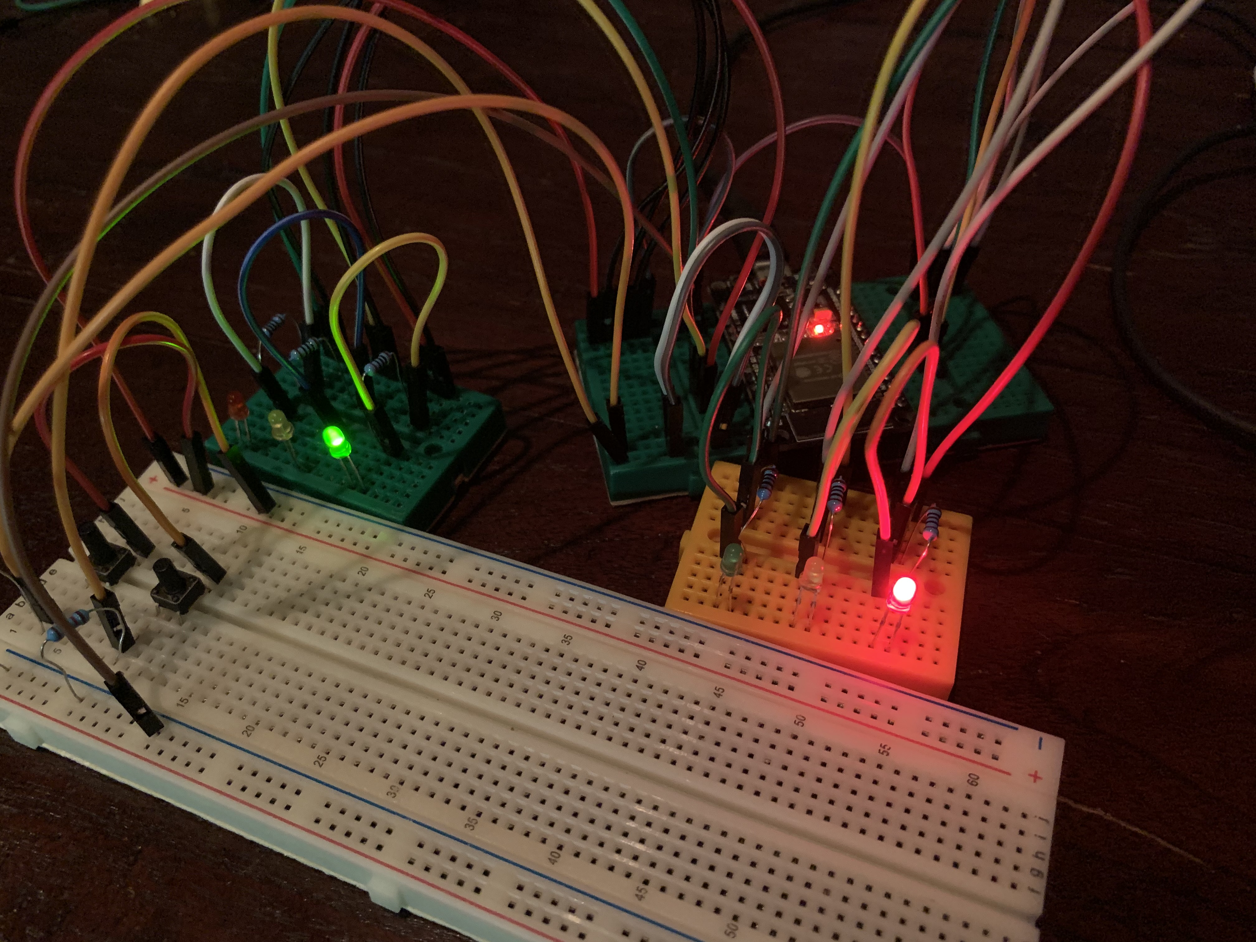
This project applies the FSM design pattern in combination with two (mini) traffic lights. These lights can switch states, depending on a button press or timer.
Transitions
The following states and transitions have been implemented for each traffic light.
| State | Transitions To State | Cause Of Transition |
|---|---|---|
| Out Of Order | Red | Boot |
| Red | Green | Button press |
| Green | Orange | Button press |
| Orange | Red | Delay |
Parts List
The following parts have been used, alongside a few breadboards and jumper wires.
| Parts | Amount | Description |
|---|---|---|
| ESP32 | 1 | Board |
| 10K Ohm resistor | 2x | One for each tactile button |
| 100 Ohm resistor | 6x | One for each LED |
| Red 1.8 mm LED, Orange 1.8 mm LED, Green 1.8 mm LED | 2x | Three for each traffic light |
| Tactile button | 2x | One for each traffic light |
Digital Pins
The following digital pins have been connected from the ESP32 to LED and buttons.
| Hardware | Digital Pin |
|---|---|
| TrafficLight 1 Red LED | 18 |
| TrafficLight 1 Orange LED | 19 |
| TrafficLight 1 Green LED | 21 |
| TrafficLight 1 Button | 22 |
| TrafficLight 2 Red LED | 33 |
| TrafficLight 2 Orange LED | 32 |
| TrafficLight 2 Green LED | 25 |
| TrafficLight 2 Button | 23 |
Hardware Schematics

Project Overview

Transitions
The following states and transitions have been implemented for each disco LED.
| State | Transitions To State | Cause Of Transition |
|---|---|---|
| Off | On | Startup leds |
| On | Chosen State | Button press |
| Flickering | Chosen State | Button press |
| Loop | Chosen State | Button press |
| Uneven | ChosenState | Button press |
| Even | ChosenState | Button press |
| Chosen Led | ChosenState | Button press |
Parts List
The following parts have been used, alongside a few breadboards and jumper wires.
| Parts | Amount | Description |
|---|---|---|
| ESP32 | 1 | Board |
| 100 Ohm resistor | 6x | One for each LED |
| White 1.8 mm LED, Pink 1.8 mm LED, Red 1.8 mm LED, Purple 1.8 mm LED, Lightblue 1.8 mm LED, Green 1.8 mm LED, Yellow 1.8 mm LED, Darkblue 1.8 mm LED | 1x | Lights for all the effects |
Digital Pins
The following digital pins have been connected from the ESP32 to LED and buttons.
| Hardware | Digital Pin |
|---|---|
| 1 Blue LED | 15 |
| 1 Red LED | 4 |
| 1 Green LED | 5 |
| 1 LightBlue LED | 18 |
| 1 Pink LED | 19 |
| 1 Orange LED | 21 |
| 1 Red LED | 22 |
| 1 Pink LED | 23 |
Hardware Schematics

Project Overview
This project interfaces two Zigbee (XBEE) modules for communication purposes between hardware setups (multiple ESP's, for example).
AT-mode

To test the two XBEE-modules an ESP32 has been used, combined with a notebook with XCTU installed. The XBEE-module connected to the notebook was configured as End-device, while the module connected to the ESP32 was set to function as coordinator.
| ESP-Pin | XBEE-Pin |
|---|---|
| GND | VSS |
| 3.3V | VCC |
| RX | DOUT |
| TX | DIN |
The XCTU-configuration for, respectively, the end-device and coordinator looks like the following.


After uploading the sketch the functionality can be demonstrated by sending a simple message string from the coordinator, which is being received on the XBEE-module configured as end-device.

Command-mode
The Xbee-module(s) can also be operated from Command Mode. This allows more advances configuration and other actions to be performed. These can be grouped in a few categories.
| Categories |
|---|
| Special Commands |
| Networking and Security Commands |
| RF Interfacing Commands |
| Sleep Commands |
| Serial Interfacing Commands |
| I/O Settings Commands |
| I/O Line Passing Commands |
| Diagnostic Commands |
| Command Mode Options |
Each section contains various commands. Commands can be sorted by section:
| Special Commands |
|---|
| WR (Write) |
| RE (Restore Defaults) |
| FR (Software Reset) |
| Networking and Security Commands |
|---|
| C8 (802.15.4 Compatibility) |
| CH (Operation Channel) |
| ID (Network ID) |
| DH (Destination Address High) |
| DL (Destination Address Low) |
| MY (Source Address) |
| SH (Serial Number High) |
| SL (Serial Number Low) |
| MM (MAC Mode) |
| RR (Xbee Retries) |
| RN (Random Delay Slots) |
| ND (Network Discovery) |
| NT (Node Discover Timeout) |
| NO (Node Discovery Options) |
| DN (Discover Node) |
| CE (Coordinator Enable) |
| SC (Scan Channels) |
| SD (Scan Duration) |
| A1 (End Device Association) |
| A2 (Coordinator Association) |
| AI (Association Indication) |
| DA (Force Disassociation) |
| FP (Force Poll) |
| AS (Active Scan) |
| ED (Energy Detect) |
| EE (Encryption Enable) |
| KY (AES Encryption Key) |
| NI (Node Identifier) |
| NP (Maximum Packet Payload Bytes) |
| RF Interfacing Commands |
|---|
| PL (TX Power Level) |
| PM (Power Mode) |
| CA (CCA Threshold) |
| Sleep Commands |
|---|
| SM (Sleep Mode) |
| ST (Time Before Sleep) |
| SP (Cyclic Sleep Period) |
| DP (Disassociated Cyclic Sleep Period) |
| SO (Sleep Options) |
| Serial Interfacing Commands |
|---|
| BD (Interface Data Rate) |
| NB (Parity) |
| RO (Packetization Timeout) |
| D7 (DIO7/CTS) |
| D6 (DIO6/RTS) |
| AP (API Enable) |
| I/O Settings Commands |
|---|
| D0 (DIO0/AD0) |
| D1 (DIO1/AD1) |
| D2 (DIO2/AD2) |
| D3 (DIO3/AD3) |
| D4 (DIO4) |
| D5 (DIO5) |
| D8 (DIO8) |
| P0 (PWM0) |
| P1 (PWM1) |
| P2 (SPI) |
| M0 (PWM Duty Cycle) |
| M1 (PWM Duty Cycle) |
| P5 (SPI_MISO) |
| P6 (SPI_MOSI) |
| P7 (SPI_SSEL) |
| P8 (SPI_SCLK) |
| P9 (SPI_ATTN) |
| PR (Pull-up/Down Resistor Enable) |
| PD (Pull-up/Down Direction |
| IU (I/O Output Enable) |
| IT (Samples before TX) |
| IS (Force Sample) |
| IO (Digital Output Level) |
| IC (DIO Change Detect) |
| IR (Sample Rate) |
| RP (RSSI PWM Timer) |
| I/O Line Passing Commands |
|---|
| IA (I/O Input Address) |
| T0 (D0 Timeout) |
| T1 (D1 Output Timeout) |
| T2 (D2 Output Timeout) |
| T3 (D3 Output Timeout) |
| T4 (D4 Output Timeout) |
| T5 (D5 Output Timeout) |
| T6 (D6 Output Timeout) |
| T7 (D7 Output Timeout) |
| PT (PWM Output Timeout) |
| Diagnostic Commands |
|---|
| VR (Firmware Version) |
| VL (Version Long) |
| HV (Hardware Version) |
| DB (Last Packet RSSI) |
| EC (CCA Failures) |
| EA (ACK Failures) |
| DD (Device Type Identifier) |
| Command Mode Options |
|---|
| CT (Command Mode Timeout) |
| CN (Exit Command Mode) |
| AC (Apply Changes) |
| GT (Guard Times) |
| CC (Command Character) |