P3 Matrix RGB LED 64x32 HUB75E
vmisiek opened this issue · comments

Hello
I bought such a panel P3 64x32 HUB75E, I connected it so in the picture https://imgur.com/a/GWmf2iA and I have a problem with the display I tried also to connect the pin E but without improvement https://imgur.com/a/MgHxff2 please help , the panel is on FM6126A chips. https://www.aliexpress.com/item/P3-RGB-pixel-panel-HD-display-64x32-dot-matrix-p3-smd-rgb-led-module/32728985432.html?spm=a2g0s.9042311.0.0.41ff4c4dVj3G0P

This seems to be the same as my issue #745 - it's exactly the same panel and I'm seeing the same issue as you.
Thank you, I wrote to the seller, I will send the second panel with a different chip.

Hi,
I got those same panels from that seller and had the same issue with nothing being displayed, Using the smartmatrix library I just got a noisy display with bits of the demo application appearing occasionally.
After lots of messing around I found out that by default FM6126 settings are the outputs are all disabled, I've been messing around with the attached script to try and work out what the various registers do, it's set to use the pinout used by the adafruit matrix hat without the RTC so see if it works for you, Just run it before the demos to configure the 2 configuration registers
For info what i've found so far is register 12 controls brightness/gain settings and appears to be made up of three 6bit values, as follows aaaaaabbbbbbcccccc a= darkness? mainly seems to add red to the background when the leds are off, b=main brightness c=finer brightness control (i'm not sure if b & c are actually as 12 bit value but with b set to all 1's the value in c doesn't seem to make much difference)
register 13 i'm not sure what it's doing yet, just that 1 specific bit within seems to be an overall enable function.
set all the values at the top to the same value for each of register 12/13 to get the same settings across the panel, the current code loads different settings into each 32 columns.
clocking in the register is simply clocking in the value (i've 2 panels so 128bits of data) and for the last 12/13 bits depending on the register setting the latch to high. the final drop of latch to low clocks in the configuration. this is done by sending the same value to r1/r2/g1/g2/b1/b2 at the same time to load the config into all the FM6126 chips
Hopefully this will help you get these panels working for you.
PS, The code is not going to win any competitions for quality, this is my first attempt to learn a bit of python along with trying to work out how to use these panels.

Hi @shades66...I am the author of PxMatrix (https://github.com/2dom/PxMatrix) and users have an issue that is probably related. I messed about with theses panels myself however did not try to write the configuration registers yet.
With the configuration you supplied above can you run the startdard library without any problems/changes? The Chinese pdf mentions something about three clock edges to pipe data into the registers - is that still necessary for display data?

I dug up an old rbpi from work, installed raspbian and hooked up the panel.
I changed the above script to support single panel and the default wiring mode and it worked. (yay)
I need to re-run the script on power cycle, so not sure if I can easily load this, then connect to pxmatrix and test. If I find some time (not sure when), I will see if I can reproduce the above script in pxmatrix init code.
(Also noticed that the brightness setting on the demo apps do not work anymore.)
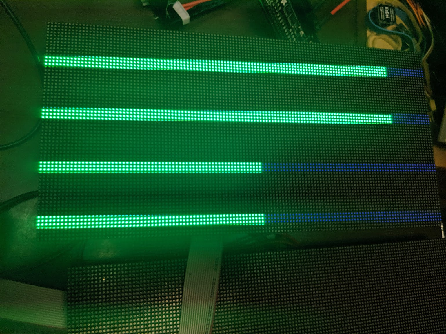
I managed to get my panels "working" too using this script, but unfortunately it's not quite 100%... 50%, to be exact - my panel is lighting up brightly on the left hand side (away from the input connector) and really dimly on the right (Image). I played around with multiplexing options and rows/cols but no luck. Anyone seen this? It's doing it on both my panels, whether they're connected separately or together.
That is easy enough to fix, the script sets this explicitly.
Change:
b12a="0111111111111111"
b12b="0111100000111111"
b12c="0111111111111111"
b12d="0111100000111111"
to
b12a="0111111111111111"
b12b="0111111111111111"
b12c="0111111111111111"
b12d="0111111111111111"
Those 'b' bits are brightness (see description above).
Video of it working: https://filebin.pw/sJD/
Hey, sorry I should of set it all to ones when I posted the script. It was just left with the last settings I was playing with trying to work out how the last 6 bits change the brightness.
I see @2dom has added the script to PxMatrix so going to give that a go too at the weekend.

Thanks to this thread, after hours trying to figure out what I had done wrong, I FINALLY realized that I too had ordered these P3 64x32 panels with HUB75E. The above script worked for me as well! (Thank you shades66!). I'm hoping to develop some software using this library to control my panels - I'll keep an eye on this thread and update if I find a nice way to integrate this little script into my project!
Massive thanks to all of you in this thread. You can't possibly understand my relief after all this troubleshooting!

Had the same problem with those same p3 modules.
The script worked for me also,
I also changed the pin mapping for it to work with the rpi-rgb-led-matrix active pcb (on output 0 top row)
And I modified it so it can activate 4 p3 pannels instead of 2.
You can get even more in a chain by multiplying max at line 56 (2 = 4 panels)
Oups couldn't upload the script for some reason, let me know if anyone needs it
Oups couldn't upload the script for some reason, let me know if anyone needs it
Please send :)
Here it is (github doesn't want python files, had to add .txt extension)
resetmatrix.py.txt

Hi all,
I exactly have the same problem, and I also connected my system like in the picture https://imgur.com/a/GWmf2iA as shown by @vmisiek. So my Raspberry PI3B+ is directly connected to the Panel's HUB75 input (without using Adafruit hat), and the Panel's HUB75 output is not connected.
I bought my panels like many of you in SRYLED Display Store and it has FM6126A chips.
So I wanted to apply @shades66's patch (with b12a, b12b, b12c, b12d values for brightness management as @DaveDavenport explained)...
The problem is that I'm not sure I correctly applied the patch (I'm only "playing" with rpi-rgb-led-matrix" for 2 days).
I just wrote sudo python3 resetmatrix.py and I got the following result :
pi@raspberrypi:~ $ sudo python3 resetmatrix.py
 0111111111111111 0111111111111111 0111111111111111 0111111111111111 0111111111111111 0111111111111111 0111111111111111 0111111111111111 0111111111111111 0111111111111111 0111111111111111 0111111111111111 0111111111111111 0111111111111111 0111111111111111 01111*11111111111
 0111111111111111 0111111111111111 0111111111111111 0111111111111111 0111111111111111 0111111111111111 0111111111111111 0111111111111111 0111111111111111 0111111111111111 0111111111111111 0111111111111111 0111111111111111 0111111111111111 0111111111111111 0111*111111111111
When I launched the following command, the panel sadly stayed black, without any led powered on :(
pi@raspberrypi:~/rpi-rgb-led-matrix/examples-api-use $ sudo ./demo --led-rows=32 --led-cols=64 --led-chain=1 -D0
[sudo] Mot de passe de pi :
Size: 64x32. Hardware gpio mapping: regular
Press <CTRL-C> to exit and reset LEDs
I'm quite sure I didn't correctly applied the patch !
Edit: I say I'm quite sure, because it now works using a nodeMCU ESP8266 after applying the patch explained by @DaveDavenport and @2dom in (2dom/PxMatrix#53). This patch is dealing with the same fix you explained in this thread.
Sorry for the total newbie question, but does anyone could tell me how I should proceed ?
Thanks in advance, and sorry again for the level of the question !

At this point I’d like to weigh in, I’ve had massive success with these panels off ebay:
https://www.ebay.co.uk/itm/RGB-P5-HD-led-screen-display-module-64x32-dots-led-display-module-matrix-32x16cm-/272157114633
So I decided to try my luck with the panels everyone on here are having issues with, (I didn’t know there were issues until I bought them).
https://www.amazon.co.uk/gp/product/B07D5RFGMF/ref=ask_ql_qh_dp_hza
After banging my head against a wall for over a day (I’ve only been messing with these panels for a couple of weeks and I’m an absolute noob with the code etc) This thread has helped me out massively.
I have 4 of these panels and realise now that the resetmatrix.py file thanks too @shades66’s hard work (which I then updated to get full panel brightness thanks to @DaveDavenport) needs to be ran on each panel individually first before you push any data to them, I then ran some demos using the sudo ./led-image-viewer image.png –led-rows=32 –led-cols=64 –led-chain=2 works great also you can use the –led-pixel-mapper=U to use 2 panels as one 64x64 panel.
Just tried to run these in a chain of 4 panels but for some reason the last two panels always remain off, still scratching my head.
Thanks for everyones hard work on here, what a great community.
I have 4 of these panels and realise now that the resetmatrix.py file thanks too @shades66’s hard work (which I then updated to get full panel brightness thanks to @DaveDavenport) needs to be ran on each panel individually first before you push any data to them, I then ran some demos using the sudo ./led-image-viewer image.png –led-rows=32 –led-cols=64 –led-chain=2 works great also you can use the –led-pixel-mapper=U to use 2 panels as one 64x64 panel.
Hi @Shemham, could you tell me how you applied the resetmatrix.py patch please (what is the command ??) : sudo python3 resetmatrix.py ?
I have 4 of these panels and realise now that the resetmatrix.py file thanks too @shades66’s hard work (which I then updated to get full panel brightness thanks to @DaveDavenport) needs to be ran on each panel individually first before you push any data to them, I then ran some demos using the sudo ./led-image-viewer image.png –led-rows=32 –led-cols=64 –led-chain=2 works great also you can use the –led-pixel-mapper=U to use 2 panels as one 64x64 panel.
Hi @Shemham, could you tell me how you applied the resetmatrix.py patch please (what is the command ??) :
sudo python3 resetmatrix.py?
Yes that's exactly how I applied it, sudo python3 resetmatrix.py I'm using the Adafruit Matrix Bonnet though, If I have 2 panels connected it seems ot apply to both panels, however if I have 4 panels connected in a chain the first two panels output OK but the last two in the chain display garbage, I'm still scratching my head.
@schnibel for my own setup, all I had to do was run sudo python3 resetmatrix.py once on rebooting the pi before running any demos. My output looked identical to yours. I'm using an Adafruit HAT, however.
@Shemham have you tried the modified script that @lucasParis wrote?
And I modified it so it can activate 4 p3 pannels instead of 2.
@Shemham have you tried the modified script that @lucasParis wrote?
And I modified it so it can activate 4 p3 pannels instead of 2.
If I run @lucasParis's code as it is (I believe he's already modified it to support 4 panels) then I only get the below output.

Ok making inroads, I had to use the original code from @shades66 with the fix from @DaveDavenport then update lines 56 to include max = 128 *2 also I needed to change line 57 to for x in range(max): same for line 94 for x in range(max): & line 124 if(x==(max-13)):
I now get the below image (all 4 panels on ) but the last two are dim and glitchy.


Thanks @Shemham and @patrickhirsh , it works... actually I used @DaveDavenport patch instead of @lucasParis patch... it's the only thing I changed...
This afternoon I'll chain 2 panels and I'll test if it works, and then I'll test with Adafruit Hat...
Great !!!!
Quick update, I now have all 4 panels working together, no glitches or dimming, @depili turns out it was a bad cable, once I replaced the cable linking boards 1&2 to 3&4 it works perfect, thanks for everyone's help. couldn't have done it without you. Video attached is rubbish quality thanks to my mobile camera but the real image is much deeper and no screen tearing.
Great @Shemham !
Same thing for me, it works perfectly... Couldn't have done it without you too !
I wanted to leave an additional update; I had bought two of these 64 x 64 panels from eBay.
I had tried everything to get them to work, (they're the ones with the A, B, C, D & E lines), However I was getting nothing but half a display from them, but only intermittently, often they were just blank, it wasn’t until I realised they're using the same FM6126A chips above that it occurred to me to give the resetmatrix.py fix a try. And it works! Once again @shades66 thank you, you absolute legend!
So I'm still having issues, it seems the first time I ran resetmatrix.py was a fluke, ever since I've had several areas of my 64x64 matrix different shades, see attached image, if I link 2 panels then run sudo python3 resetmatrix.py the first panel displays the image fine with 100% matrix coverage but the second panel has several areas of different brightness, i'm sure it's the terrible job i've done editing the code which is also attached but if anyone coudl point me in the right direction i'd be eternally grateful.

Hi,. In the script try updating the line
if(x==(128-12)):
To
if(x==(max-12)):
And see if that works
Thank you, that's done the trick. once again, many thanks.

Thanks so much to whomever figured this out. I have a 12 screen setup were the last 3 arrived after december. That was a big bummer when they finally arrived, my screen was complete (....for now) and 3 of them didn't work. Translated this python code to the pin-wiggles, to 6 screen-chains (have 2 of them) and then to VHDL (I use an FPGA dev-board to translate HDMI and drive the whole unit)
https://www.youtube.com/watch?v=OPDcUbJsSHU (I know, I know, I still need to remap some pixels...)
Anyhows, I was getting close to mad of searching and emailing with the not-so-helpfull chinese I bought this from when I stumbled into this thread after searching the changed IC's I'd found on the panels. And now it works \o/ I've added a link to the working panels together (they can work together with "old" panels! Don't let the seller convince you otherwise :/ ) so you may be able to join in my happiness.
Which again is thank to someone here. Thanks thanks thanks!!


Thanks for figuring out the details and writing a Python initializer!
I'll see that I can integrate this in the library directly so that people in the future have it work automatically. I don't hae a 75E panel currently to test, I have one on order at Aliexpress. But I might implement it 'blind' first, then ask this thread for you to test.
I'll keep an eye out for updates here - I'd be happy to test!

Thanks to shades66 for posting the Python initializer. For anyone using panels that have the FM6126 chip, this should solve the problem. Note that this script is specifically for the standard wiring described in the Connection section. If you are using an Adafruit Bonnet or Hat, the wiring is different and will not work. However, I have made a version of the script with a revised pin out so that it will work with the Adafruit adapters: resetmatrixAdafruit.py.txt
I have tested this using a couple of FM6126 equipped 64x64 panels from eBay: 64x64 panels

Hello! Any idea on how to use the initializer so that it can be used on an adapter? I have a 4x3 setups of panels. the first 2x4 chain has the old chipset while the 3rd one chain has the new one. Any fix for this?
puffycholo, I currently have three 64x64 panels chained together. One has the older FM6124 chips and the other two have the FM6126 chips. In my configuration the older panel is last in the chain. I am using the Adafruit Bonnet adapter on a Pi 3. As long as I run the resetmatrix script (AdaFruit variant) before running rpi-rgb-led-matrix, all three panels work properly. In fact, I put the resetmatrix initializer call in my /etc/rc.local file so that it runs automatically each time the pi is booted. Of course this is temporary as I know that hzeller is planning to add built-in support for the FM6126 at some point.

Massive thanks to all of you, thanks to these scripts I managed to get my displays working.

Why i receive this error ?
sudo python3 ./set.py
Traceback (most recent call last):
File "./set.py", line 4, in
from gpiozero import LED
ImportError: No module named 'gpiozero'
If you are using Raspbian Lite, GPIO Zero is not installed by default. So all that you need to do is install the library to fix this error.
sudo apt update
sudo apt install python3-gpiozero
I am trying to use Tiny Core for the problem of Flikr.
It seems there is not in the repository
tc@box:~$ tce-load -w python3-gpiozero
Downloading: python3-gpiozero.tcz
Connecting to repo.tinycorelinux.net (89.22.99.37:80)
wget: server returned error: HTTP/1.1 404 Not Found
md5sum: python3-gpiozero.tcz.md5.txt: No such file or directory
Error on python3-gpiozero.tcz
Darn, so I ordered a couple of the SRYLED panels to test the issue and put the suggested initialization logic directly into the library (thanks for the legwork @shades66 ).
However, the LED panels I received have ICN2037 chips on it, and they work right out of the box :/
I guess that is one of the situations where you one day get one batch of devices, the other day another...
Anyway, I'll see to add the initialization sequence on the weekend 'blindly' and then ask here for people to test.
Darn, so I ordered a couple of the SRYLED panels to test the issue and put the suggested initialization logic directly into the library (thanks for the legwork @shades66 ).
However, the LED panels I received have ICN2037 chips on it, and they work right out of the box :/
I guess that is one of the situations where you one day get one batch of devices, the other day another...Anyway, I'll see to add the initialization sequence on the weekend 'blindly' and then ask here for people to test.
I talked to the Sryled guys, they had so many complaints and issues with the new chip, that they switched to this one now. From what I understood they won't ship the other one any more.
Quote:
now we don't sell FM6124 and FM6126A chip led module, because some customers said it is difficult to use. Now our chip is ICN2037, it is easier to use.
(@hzeller I have one panel with the FM6126A I could possibly send it to you.)

Hello to hzeller and patrickhirsch!
I am trying to use the FM6126 modules on a non-RPI or non-phyton base and see that you have some knowledge. I successfully use modules with ICN2028 drivers but cannot get the FM6126 to work properly.
Can you please give me some description on the configuration registers of the FM6126 and how to access them?
With kind regards
Friedrich
Hello to all.
Got the FM6126 to work as expected :)
BUT had to pull the barf bag for this.
The datasheet is s..t.
For your enlightenment: if you want to latch the data into the output register you have to rise LE three clocks before the end of the line!!! With the last three clock pulses then the data have to be applied also. Makes things a LOOOT easier - hmmm?
rgds

Having the same problem, in my case I use a different driver board, this one http://ledpixelart.com/pixelv2board/. This board worked fine on the ICN2028 chipset but with FM6126, just a dead screen. Henner, thanks for the tip on SYRLED, am going to try those, would you or anyone happen to know if ICN2037 behaves the same way as ICN2028?

So I have some FM6126 panels, which are apparently equivalent to the ICN2038S/2045 (or at least that's what they're configured as in the Linsn software), and some Linsn hardware to drive them. The Linsn stuff has a UI that lets you tweak the config and shows the register values; this is what it calls the various bits:
reg1
76543210 76543210
 ####             Low blanking grade
     ### #        Current gain
1         1       Always 1

reg2
76543210 76543210
     #            Delay active
      #           Open time-share
       #     #    Low blanking mode enhace (both 1)
               ## Low grayscale 0-2
           1      Always 1

reg3
76543210 76543210
              ### Delay time (16ns + 8*n)

Many Thanks to @shades66 and Dave Davenport! I have been trying to get some of these panels to work for weeks and your resetmatrix.py code fixes it. I have also been trying to port the code to an Arduino with limited success.
The Arduino code is now at: https://bobdavis321.blogspot.com/2019/02/p3-64x32-hub75e-led-matrix-panels-with.html

Hi @shades66 I'm having woes trying to get a 64x64 2.5mm pitch panel working both with and without the Adafruit Bonnet. How would I change the resetscript to try and fix my 64x64 panel ?

Hi,
@shades66 , I recently purchased this screen (64x64 p2.5 with FM26126A) and been trying to control it since then. I have read the solutions here and tried them. Moreover, I am developing the code on altera FPGA (VHDL).
I think I managed to load the configuration in the registers but my problem is that I am not able to provide an output. I am currently looping over all the addresses (rows) which causes the rows to light up. But the lighting is random and does not seem to respond to my controller's RGB output.
Maybe @stevie-the-tv can help me too?
Hey after much faffing I managed to get things to work with the script and the Adafruit Bonnet, plus for the record two 64x64 2.5mm pitch panels work fine with an 8amp power supply with all the demos so happy days.
I am currently getting this imageHere and I have no idea whether this is an issue of configuration or sending the data to display. This is supposed to display a red line at 0 and 33 and the rest blue.
Hi, do you mean the configuration is not correct? Honestly I am confused by the many solutions posted here. I have tried the python solution and the PxMatrix class and even tried translating the original Chinese datasheet in order to interpret the diagrams in it, but unfortunately each one of these indicated a different method and it seems that all did not work for me. Can you please list the initialization process in order with the specification of how signals must be asserted?
The panel reset is not working correctly. I have seen similar stuff with the Arduino reset code not being correct.
…
On Mon, Mar 25, 2019 at 5:58 PM HousseinSayed @.***> wrote: I am currently getting this imageHere https://photos.app.goo.gl/nwiS2yw4xu2mCJoT9 and I have no idea whether this is an issue of configuration or sending the data to display. This is supposed to display a red line at 0 and 33 and the rest blue. — You are receiving this because you commented. Reply to this email directly, view it on GitHub <#746 (comment)>, or mute the thread https://github.com/notifications/unsubscribe-auth/AjlVggoiyRe7LV3RyCtxa9Xq6-4QTmeVks5vaUaAgaJpZM4ZyCzn .
Thank you for your haste response. So let me get this straight, first of all I need to configure the registers 12 and 13 by sending (64 bits of configuration to each register). 1-The latch signal should be set to high for 12 or 13 clock cycles during the last 12 or 13 bits of data to be send? 2- Or should it be set to high after that data is sent?
3-After sending the configuration, should I send no clock pluses to blank the screen?
4-For how many clock cycles the sent clock should be blanked?
5-When should I use blanking (for configuration, after or before sending data to be displayed)?
6-Concerning the OE signal, I have zero clue about it and how it is supposed to be asserted in this LED panel. Could you please emphasize more on this signal?
I am sorry for the loads of questions here. I really appreciate any piece of information that can be provided. It is really a great job you people have done here to control this weird Chinese LED.
hi, "1-The latch signal should be set to high for 12 or 13 clock cycles during the last 12 or 13 bits of data to be send?" that is the correct method. basically set LE high for the last 12/13 bits and then set LOW which will load the config into the matching configuration register. (note that the settings for A/B/C/D & E if used don't matter as they share the same config for all rows so only needs sending once)
I'm not sure what you mean by blanking in 3/4/5. you don't need to switch each row off after sending the data, just load the pixel data for the next row, latch it and then pulse OE low to light up the LED's.
OE isn't used to set the configuration it's only used after sending the pixel data to light the relevant leds before you put it HIGH again and send the next row. (A simple overview can be seen here https://www.sparkfun.com/sparkx/blog/2650 )
your attached image above looks like incorrect configuration in register 13 as that is what I saw when i was experimenting originally.
Hi, I did as you said @bobdavis321 and @shades66 . So I have a good result (thank you) and a bad one. First of all, the panel seems to be more controlled image. This is supposed to be all white. But I end up with a block of color cyan at the corner. This means that the color red is not working. Any guesses ?
Power supplies
You do not have homogeneous tension on all panels.
Use biggher and shorter wire.

I've been having these issues with my FM6126A matrix and, while the reset script works for me, my display still glitches up and freezes after a spending some time running. Without the reset script, I can't even get this far. Anyone else seeing these issues? Using an Adafruit hat fwiw.
Video here: https://www.dropbox.com/s/i8whfc29lti7nhm/IMG_6047.MOV
Quick update: this morning I bridged pins 4 and 18 on my hat and started using adafruit-hat-pwm mapping and everything works fine. weird that this was enough but happy to be done with it
I have ported the reset code to the Teensy 3.x processor: http://bobdavis321.blogspot.com/2019/03/teensy-31-and-smartmatrix-sd-running.html
Hi, @bobdavis321
Can you play uncompressed video from SD or USB flash, with Teensy ?

I've got a pair of P2.5 64x64 (FM6124, HUB75E) matrix from DHGate. They are connected to a Pi via the Adafruit Bonnet. I've got a jumper soldered between pins 4 and 18 and I've got the middle pad shorted to 8. I also tried shorting it to 16.
I've tried the each of the reset scripts, but when running demo 0 I get a bunch of random colored lines. Does anyone have a suggestion?
@bobdavis321 It looks like it. This bonnet works on the 64x64 panels I bought directly from Adafruit, but not these that I got from China. The tape is just holding the wire down that I had to use for a jumper. It is soldered in underneath. I can provide more/better photos if needed.

If your 64x64 panels have the HUB75E connector (with E on pin 8), then you need to solder a jumper on the bottom of the Adafruit bonnet board between E and 8.
If you want the reduced flicker option, you can add a jumper from GPIO 4 to GPIO18 (which it looks like you have done). In this configuration, you will need to use the Hardware gpio mapping option:--led-gpio-mapping=adafruit-hat-pwm.
Since your panels have the FM6124 chips and not the FM6126 chips, you will not need to use the python initialization scrip.
Based on what you have said, the command line that you would use for one panel would be something like:
sudo ./demo --led-gpio-mapping=adafruit-hat-pwm --led-rows=64 --led-cols=64 -D0

The script given works with the bonnet, but not with the shield which has an RTC clock and different pin mapping.
Here is a reset version for the RGB shield:
resetmatrix_adafruit.py.txt
@bobdavis321 thanks for your arduino code. There is a small issue with the code on your webpage (it's missing code when you pasted and doesn't compile).
I tried to fix it here, but may have missed something.
Could I ask you to send me a PR against https://github.com/marcmerlin/SmartMatrix/blob/FM6126A/examples/FM6126A_reset/FM6126A_reset.ino
and subscribe to
https://community.pixelmatix.com/t/smartmatrix-doesnt-support-fm6126a-driver-chips/421/5 ?
@vmisiek could you rename this issue to be "FM6126A init support needed for panel to work" ?
Thanks @bobdavis321 . Since this is arduino related, do you mind if we move to pixelmatix/SmartMatrix#78 ? I did put maxleds to 256 which should have worked either way given that my panel was 64x32.
https://github.com/marcmerlin/SmartMatrix/blob/FM6126A/examples/FM6126A_reset/FM6126A_reset.ino
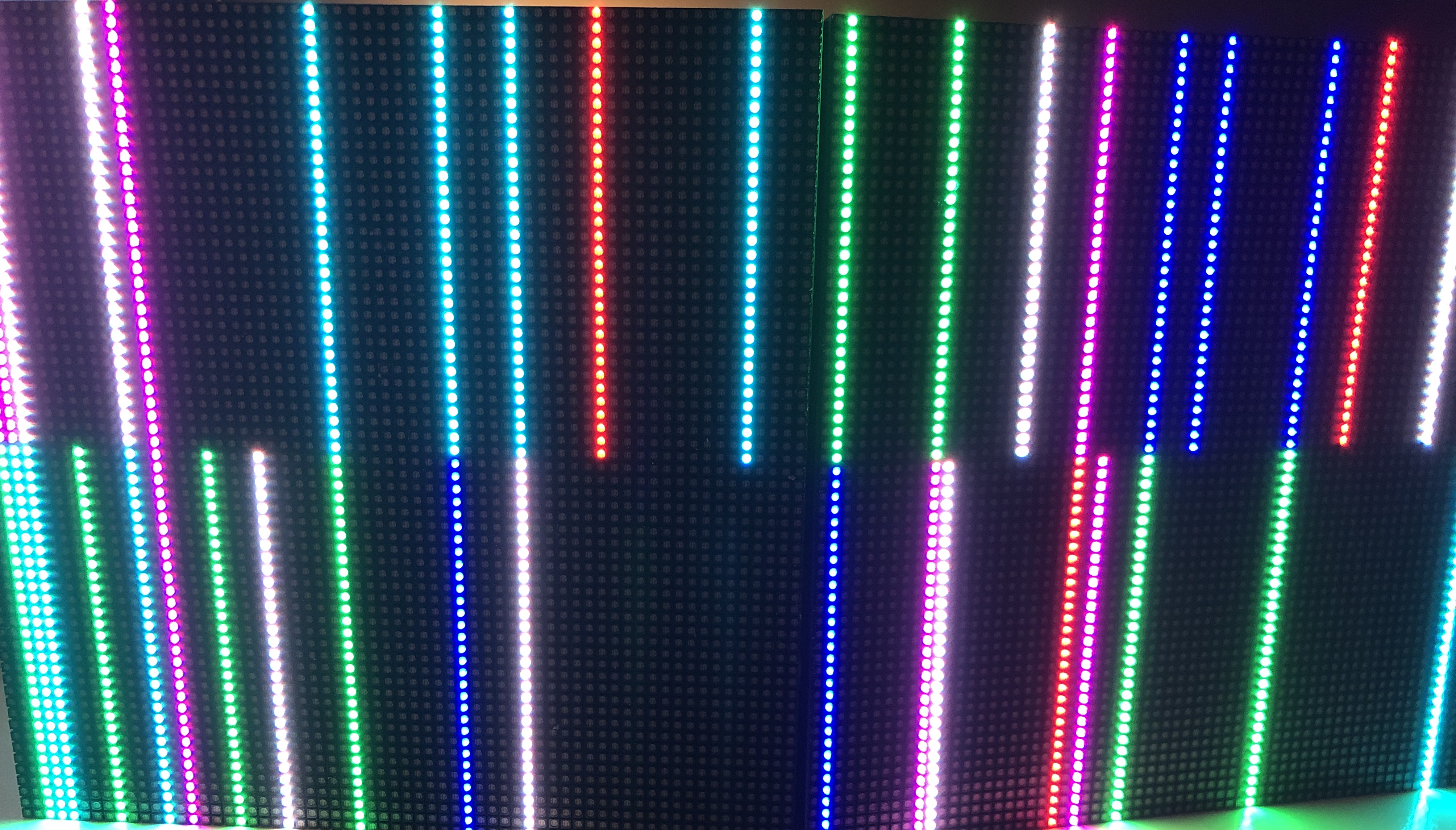
So, reset_matrix works, but on wider panels (here 128x64 ABCDE), I have to run it multiple times until the entire panel on all colors, gets turned on. Sometimes I get one color all the way through and not the other ones
See picture (ignore the vertical bars, that's the refresh rate being too slow)
So the script does help a lot, but there is a timing problem
I'm also having issues getting this to work with the active3 board. When I activate port #2, port #1 stops working.
I have to unplug port #1 while activating port #2 and then both work.
But this is starting to be a bit annoying :)
Attached the script, all I did was change the port numbers for RGB1/2, but I guess the clock and reset signals are being sent to all panels, so port #1 gets broken while port #2 gets fixed.
I've just opened a proper bug to track FM6126A and see if @hzeller may have an idea: #807
I'll continue on the new bug, but I made a script that works on all ports of the active-3 board

Hi, I will not go into how many weeks I have spent trying to get my panel to work.
I have a question how do you use the Reset Code for the FM6126A, it's not clear.
Do I load Reset Code into Teesny run it with panel connected then compile and load my sketch or do I merge it into an existing sketch ?
Does anyone have an example of completed Teensy code?
I have same panel as vmisiek, P3 64x32 HUB75E with FM6126C Shift Reg and 74HC245C Octal Bus Trans. Connected to it I have the Teensy 3.2 and SmartMatrix v4 board.
However I did get the panel working using a Mega and RGBmatrixPanel library, but only the left 75% worked.
Using these connections. https://raw.githubusercontent.com/DFRobot/DFRobotMediaWikiImage/master/Image/DFR0499_Connection_Diagram.png
Thanks for any help.
I haev it working, I used the DFRobot library and the recommended connections. All worked first time!
I did have to use Bob's reset code which worked well and now inserted into the example code.
Thanks for reading my previous message. I can now write what I wanted to do weeks ago!
Should anyone have same issue look to DFRobot.
@Galaxy-Man which DFRobot library is that?
But yes, you have to run the reset code first. You can merge it into your own code and run it in setup, or upload the reset first, then switch to the other code you want to run, and upload/run that.

I'd be grateful if you provided some guidance on what would need to be changed in the reset script for a single 64x32 panel that relies on FM6126A. I attach the modified version that I'm trying to apply, which doesn't work (black screen).
I use a Raspberry Pi Zero, connected as per diagram here:
[(https://github.com/hzeller/rpi-rgb-led-matrix/blob/master/wiring.md)]
The rPi runs Raspbian Lite, audio has been deactivated (not listed in lsmod). Deactivated SPI, I2C and 1-wire from raspi-config. Removed bluez.
I've checked if the connections are right, hopefully I haven't screwed up there!
Update (22/6/2019): I've now replaced the color-coded DuPont jumper wires with the Adafruit RGB Matrix Bonnet, I set max_led=128, and the script worked fine! Thus, I can only assume that I misinterpreted the wiring diagram (pin numbering on the connector) as I did double check all the connections.
Hi, I will not go into how many weeks I have spent trying to get my panel to work.
I have a question how do you use the Reset Code for the FM6126A, it's not clear.Do I load Reset Code into Teesny run it with panel connected then compile and load my sketch or do I merge it into an existing sketch ?
Does anyone have an example of completed Teensy code?
I have same panel as vmisiek, P3 64x32 HUB75E with FM6126C Shift Reg and 74HC245C Octal Bus Trans. Connected to it I have the Teensy 3.2 and SmartMatrix v4 board.
However I did get the panel working using a Mega and RGBmatrixPanel library, but only the left 75% worked.
Using these connections. https://raw.githubusercontent.com/DFRobot/DFRobotMediaWikiImage/master/Image/DFR0499_Connection_Diagram.pngThanks for any help.
@Galaxy-Man marcmerlin sent me the following link that you may find useful:
https://github.com/marcmerlin/SmartMatrix/blob/FM6126A/examples/FM6126A_reset/FM6126A_reset.ino
Hi
Im using the DFRobot_RGBMatrix library
Arduino Mega
Wiring diagram as previous message
Bob's reset code as previous message
Panel works fine 100%
I am working on getting it over to the Raspberry Pi, Teensy and ESP32
I will update in a few days
Cannot do any more , I'm off to the Pub. There's a pint and bag of crisps with my name on them :-)
Merge Bob's Reset Code with this
https://wiki.dfrobot.com/64x64_RGB_LED_Matrix_-_3mm_pitch_SKU_DFR0499#target_4
DFRobot library found here
https://github.com/DFRobot/DFRobot_RGBMatrix

Hi, I am trying to use STM32 to drive the 64x64 RGB LED matrix using FM6124 chips, but I failed to turn on a “stable” pixel using GPIO simulation. I follow the procedure below:
All row selection lines (A,B,C,D,E) are low, OE high, LAT low, CLOCK low;
Select Row 1 and Row 32 by setting A=1, B=C=D=E=0;
Shift 64 bits (0xFFFFFFFFFFFFFFFF) out via R1 and R2 pin with clock;
LAT high and turn it into low after a few cycles;
OE low (Enable output).
Theoretically speaking, the procedure discribed above should turn on Row 1 and Row 32 with RED color stably, but these two lines just give me a quick “flash”.
What’s more, if the number of row I select is larger than 8, these two lines will be flicking…
Sorry to disturb you, hope can get some help here. Thanks.
Darn, so I ordered a couple of the SRYLED panels to test the issue and put the suggested initialization logic directly into the library (thanks for the legwork @shades66 ).
However, the LED panels I received have ICN2037 chips on it, and they work right out of the box :/
I guess that is one of the situations where you one day get one batch of devices, the other day another...
Anyway, I'll see to add the initialization sequence on the weekend 'blindly' and then ask here for people to test.I talked to the Sryled guys, they had so many complaints and issues with the new chip, that they switched to this one now. From what I understood they won't ship the other one any more.
Quote:
now we don't sell FM6124 and FM6126A chip led module, because some customers said it is difficult to use. Now our chip is ICN2037, it is easier to use.
(@hzeller I have one panel with the FM6126A I could possibly send it to you.)
Does that mean FM6124 also has a hidden register? I saw this piece of code from PxMatrix.
inline void PxMATRIX::writeRegister(uint16_t reg_value, uint8_t reg_position)
{
  if (_driver_chip == FM6124 || _driver_chip == FM6126A){

    if (_driver_chip == FM6124) {
       Serial.println("\nFM6124 - REG: " + String(reg_position));
    } else {
       Serial.println("\nFM6126A - REG: " + String(reg_position));
    }
    ...
}So I have added the init code now, which you can use with --led-panel-type=FM6126A.
I have only tested with a single panel that I got from @esden and was using the initialization sequence provided here in the python script further above.
Please let me know if it now works for you with this option.

Hi,
I just tried (RGBMatrix::Options) options.panel-type="FM6126A" in c++ with two 64x64 panels in a single chain.
It works nicely, but only with the following settings:
options.cols = 128 and options.chain_length = 1
instead of the previously used:
options.cols = 64 and options.chain_length = 2.
With the old settings the second display stays dark, the first one works fine in both cases.
This doesn't have any practical relevancy for me, but it's still odd. I guess with the previous setting the second Panel wasn't reset?

Just for the record:
I bought a Waveshare LED Matrix (https://www.waveshare.com/wiki/RGB-Matrix-P3-64x32) from Amazon and got really dim and washed out colors. It uses FM6047 chips on which I could not find any information.
Out of pure despair I ran the mentioned Python script with default pins and all my issues where gone. Thank you so much @shades66 and @lucasParis !
Here it is (github doesn't want python files, had to add .txt extension) resetmatrix.py.txt
How did you even know about those configuration registers?

I dug up an old rbpi from work, installed raspbian and hooked up the panel.
I changed the above script to support single panel and the default wiring mode and it worked. (yay)
I need to re-run the script on power cycle, so not sure if I can easily load this, then connect to pxmatrix and test. If I find some time (not sure when), I will see if I can reproduce the above script in pxmatrix init code.
(Also noticed that the brightness setting on the demo apps do not work anymore.)
How exactly did you do that? I tried to rewrite the script, yet my display still stays dark