 This project exists as a do-it-yourself alternative to the popular DynaMount microphone stand.
https://dynamount.com/
This project exists as a do-it-yourself alternative to the popular DynaMount microphone stand.
https://dynamount.com/
The position of a microphone relative to the centre and edges of a speaker cone has a great impact on the tonal character of a guitar tone. When tracking guitar parts in recording studios, engineers and guitarists have historically had to place a microphone on the speaker cab in an approximate position according to their desired tone. Closer to the centre of the cone yields a brighter and more focused tone, whereas further to the edge a smoother tone with a reduced high-end response is produced. This would mean adjusting the mic position, going back to the control room to check and record the tone, moving the mic slightly, checking again etc. Even the slightest adjustment can vastly change the tone meaning that it's very difficult and potentially very time consuming to achieve the best tone possible from a given speaker and signal chain.
Motorised stands solve this problem by allowing remote control of the microphone position while the engineer/guitarist is present in the control room listening to adjustments in real time. If the stand is set up and left alone throughout a whole session, then positional coordinates displayed on the stand control interface can be written down for a particular tone and recalled at a later time if a part must be re-tracked for example.
If you are considering building this project, make sure to read this document in full first.
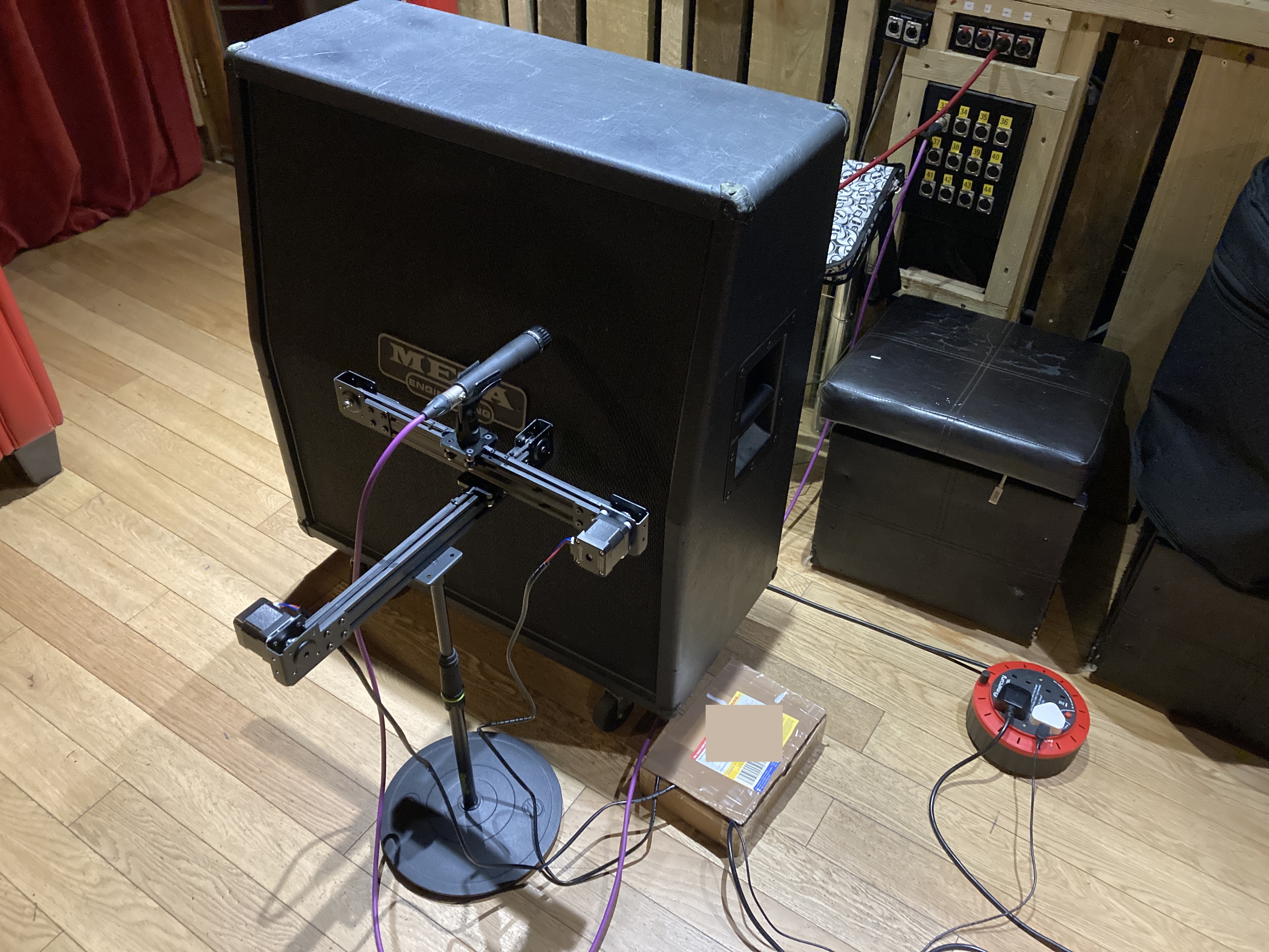
The stand is made up of two linear actuators built from V-Slot aluminium extrusions, gantry plates and wheels. These are stacked on top of one another and paired with NEMA 17 stepper motors to create a smooth horizontal and vertical motion across a 2D plane, perfect for remotely moving a microphone between the centre and edge of a speaker cone while also providing distance control for more or less room sound.
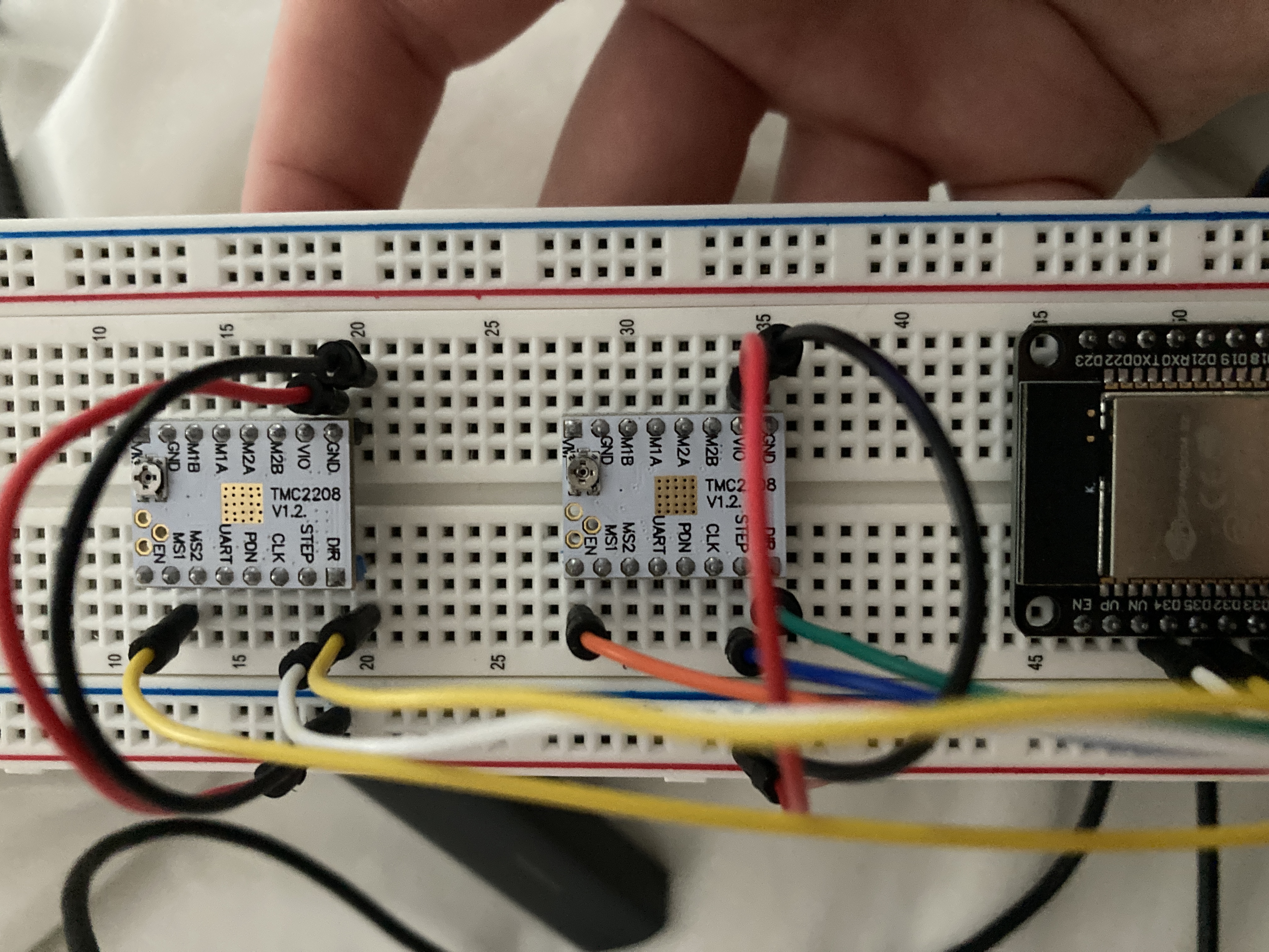
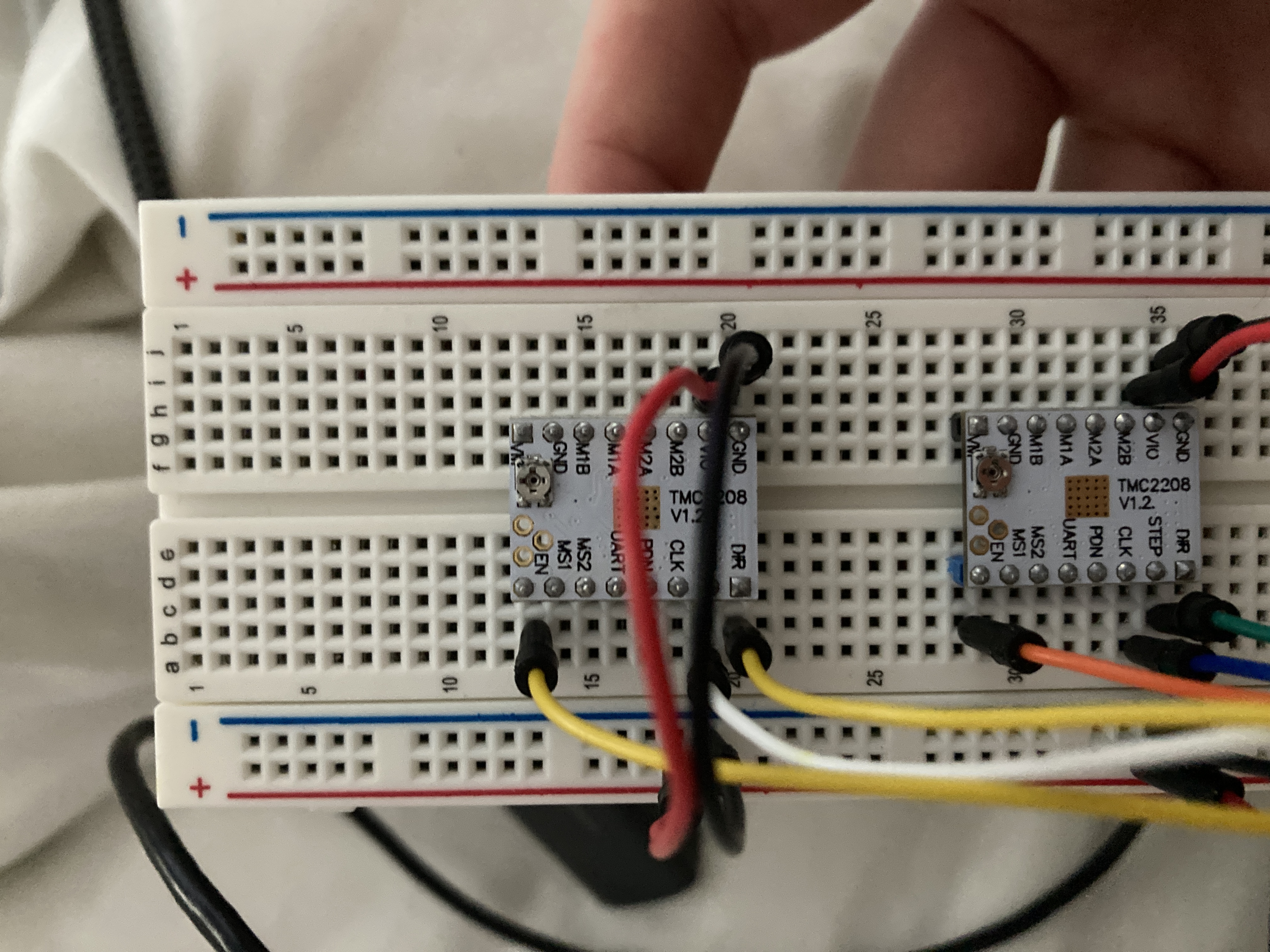
In the case of this DIY project the stepper motors are powered by TMC2208 motor drivers which use microstepping to minimise noise and rumble. These drivers are controlled by a Wi-Fi capable ESP32 SoC hosting a web server that the user can interact with through any popular web browser.
Power can be provided in one of two ways:
-
Use two power supplies to power the ESP32/motor logic and motor power separately. The ESP32 can be powered via USB at 5V or via the provided 3V3 pin at 3.3V. The motor driver's logic supply voltage must be 3.3V - 5V and its motor power supply should be 4.75V - 36V. It's important to check the manufacturer's spec sheet here.
Although the maximum 5V of the logic crosses with the minimum 4.75V of the motor power, damage could very easily be done if the whole system was powered by a single 5V supply. I used a 12V laptop supply to power the motors and a 5V USB wall adapter to power the logic. USB into the ESP32, then connect VIN and GND on the ESP32 to VIO and logic GND on the TMC2208s.
-
The other approach is come up with your own solution. There are many examples of other people encountering power issues with their Arduino projects so it would be worth browsing around to see if there is a more elegant solution to the one above. Just make sure you get a decoupling capacitor in there somewhere to soak up any noise that could end up on the 5V rail.
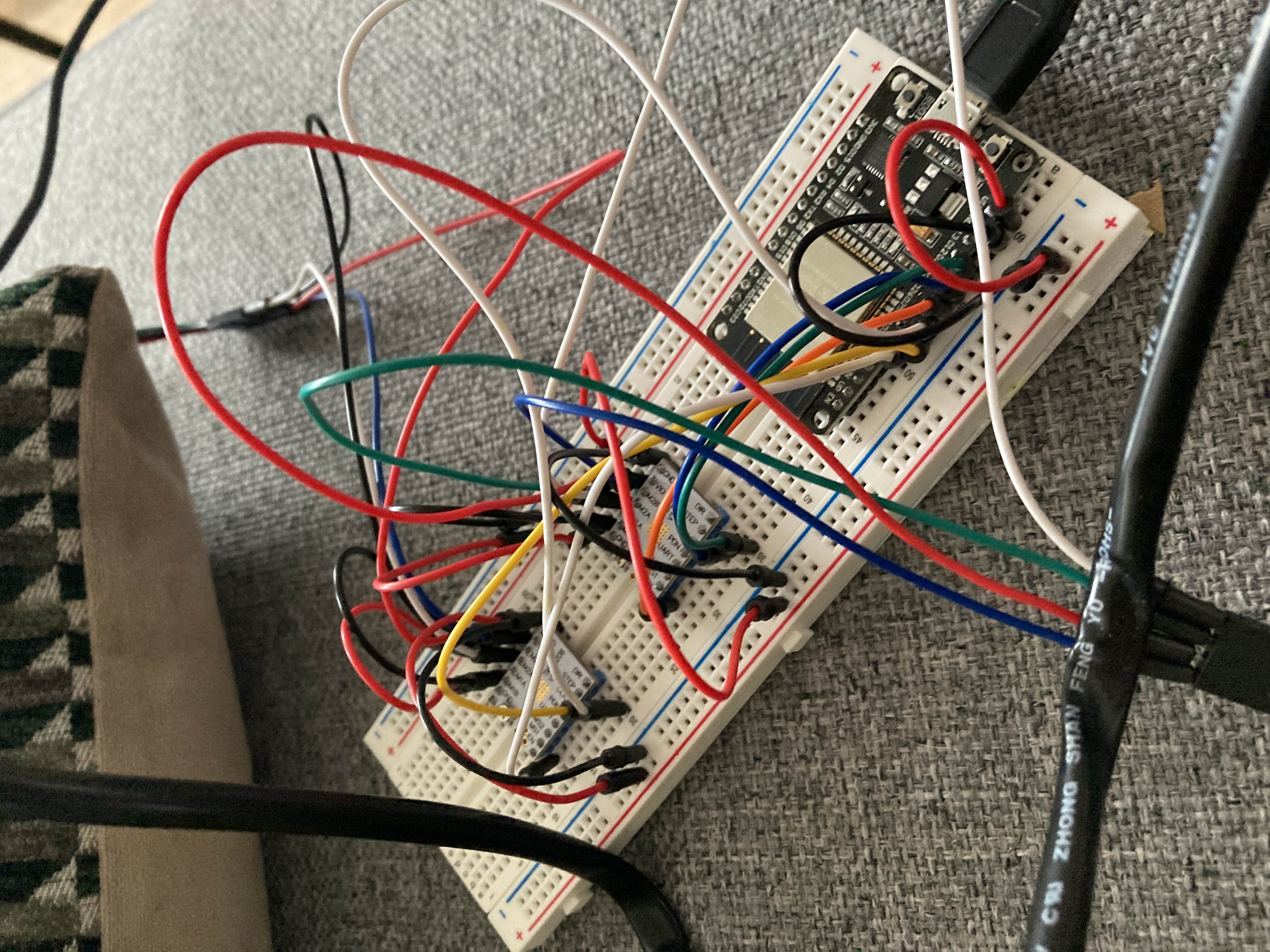
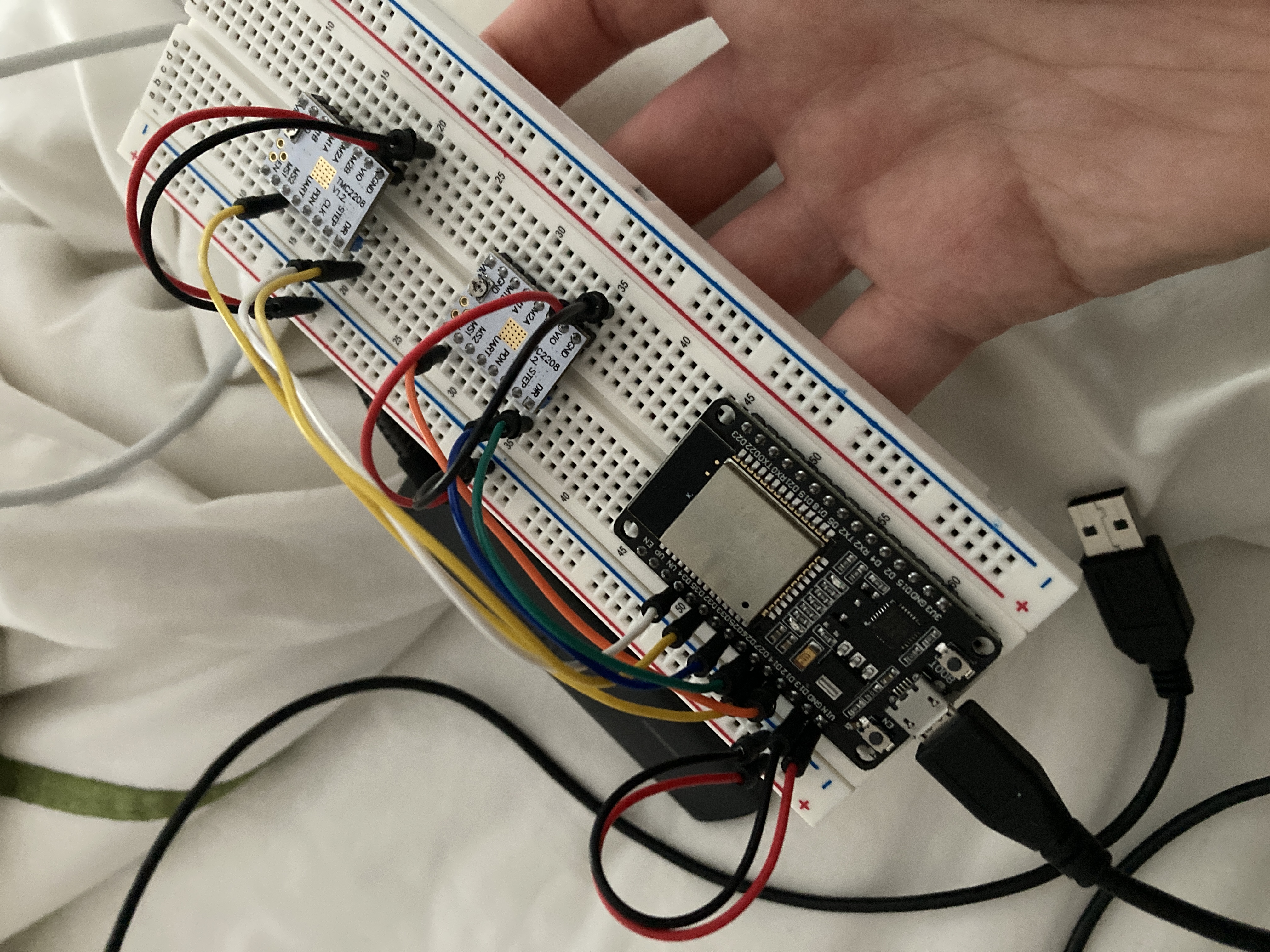
I am yet to design a PCB to go with this build so an 830 tie-point breadboard is required to get things going.
The ESP32 I used was purchased from here: ESP32-DevKitC Development Board, ESP-32, 30-pin DOIT Layout https://www.ebay.co.uk/itm/322715105223
Dependencies:
- Arduino IDE built in libraries. Arduino.h and WiFi.h - https://www.arduino.cc/reference/en/libraries/wifi/
- Arduino_JSON - https://github.com/arduino-libraries/Arduino_JSON
- ESPAsyncWebServer - https://github.com/me-no-dev/ESPAsyncWebServer
- AsyncTCP - https://github.com/dvarrel/AsyncTCP
- WiFiManager - https://github.com/tzapu/WiFiManager
- SPIFFS - https://github.com/espressif/arduino-esp32/tree/master/libraries/SPIFFS Note that SPIFFS should be installed automatically when the board is installed below.
Some of these libraries can be installed in the Arduino IDE by clicking Sketch -> Include Library -> Manage Libraries... Make sure that you have the right libraries installed by clicking "more info" in the manager for each library.
Selecting the correct board: In the Arduino IDE click Tools -> Board: -> Boards Manager... and make sure you have esp32 installed. https://github.com/espressif/arduino-esp32
There are a few lines of code that should be modified in diynamount_v03.ino which control which pins do what, and how far and fast the motors should operate. These lines are found at the top of the file just below the library includes.
#define  MOTORPOSEN  26 // HIGH turns motor off, LOW turns motor on
#define  MOTORDISTEN  32 // HIGH turns motor off, LOW turns motor on
#define  MOTORPOSDIR  14
#define  MOTORPOSSTEP  27
#define  MOTORDISTDIR  25
#define  MOTORDISTSTEP  33
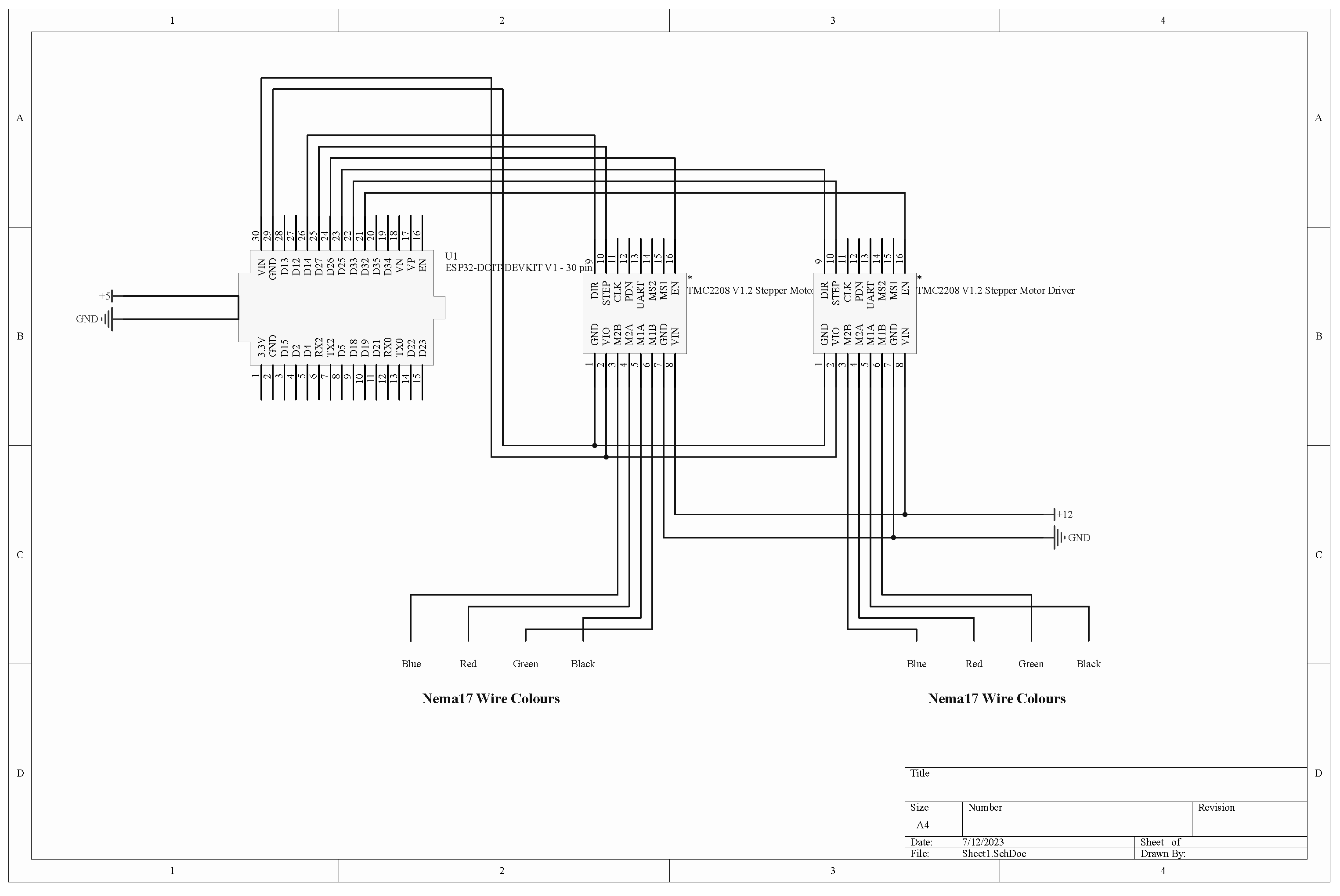
These defines are used to set which pins are used for motor driver control. Consult the schematic below for context. These numbers may need to be changed depending on your ESP32.
#define  STEPSPERUNITMOVEMENT  58
#define  MOTORSPEED  700
STEPSPERUNITMOVEMENT corresponds to the number of steps needed to move the microphone per 1 unit of movement on the web control slider. The lower the value the less the microphone will travel. Start with a low number and try moving the slider.
MOTORSPEED corresponds to the amount of time to wait between each motor step. The lower the value the FASTER the motor will run. Start with a high number and try moving the slider.
Note that the above numbers are simply what I landed on when adjusting for my build.
If your wireless network does not allocate IP addresses in the format 192.168.1.x then consider scrolling further down and changing the static IP address that the stand will request.
wm.setSTAStaticIPConfig(IPAddress(192,168,1,117), // IP address
						IPAddress(192,168,1,1), // Gateway
						IPAddress(255,255,255,0)); // Subnet mask
If you also already have a device running on 192.168.1.117 feel free to change that here too.
Once all dependencies have been installed and the code has been adjusted, open the Tools list in the Arduino IDE and set the following:
- Board: "DOIT ESP32 DEVKIT V1" (this may be different if you have a different ESP32 from the one I used)
- Upload Speed: "921600"
- Flash Frequency: "80MHz"
- Core Debug Level: "None"
Run Tools -> ESP32 Sketch Data Upload and wait for the upload to complete. This uploads the contents of the /data folder containing resources for the web server.
Run Sketch -> Verify/Compile to check that the code compiles.
Run Sketch -> Upload to upload the compiled binary to the ESP32.
This section is going to be rather short as my sources for the required parts will most likely be different to yours. There are DIY retailers out there that do kits for V-Slot aluminium linear actuators so assembling two of these is the first step.
Once you have two actuators made up, a way to connect the top one to the bottom one's gantry plate is necessary, followed by a means of mounting a microphone clip on the top actuator's gantry plate. Don't underestimate this step as there is often a metric/imperial mismatch between the linear actuator kits and microphone stands/clips. A combination of T-Slot nuts and some sort of metric to imperial mounting plate is needed here.
The whole unit must then be mounted on a short microphone stand with a heavy enough base to support all positions that the microphone can be set to. I would highly recommend Gravity microphone stands because of their heavy base: https://www.gravitystands.com/en/products/microphone-stands/2882/ms-2222-b
As mentioned previously, there is currently no PCB available so this build currently only exists on an 830 tie-point breadboard. See below for a wiring schematic along with some supporting images.
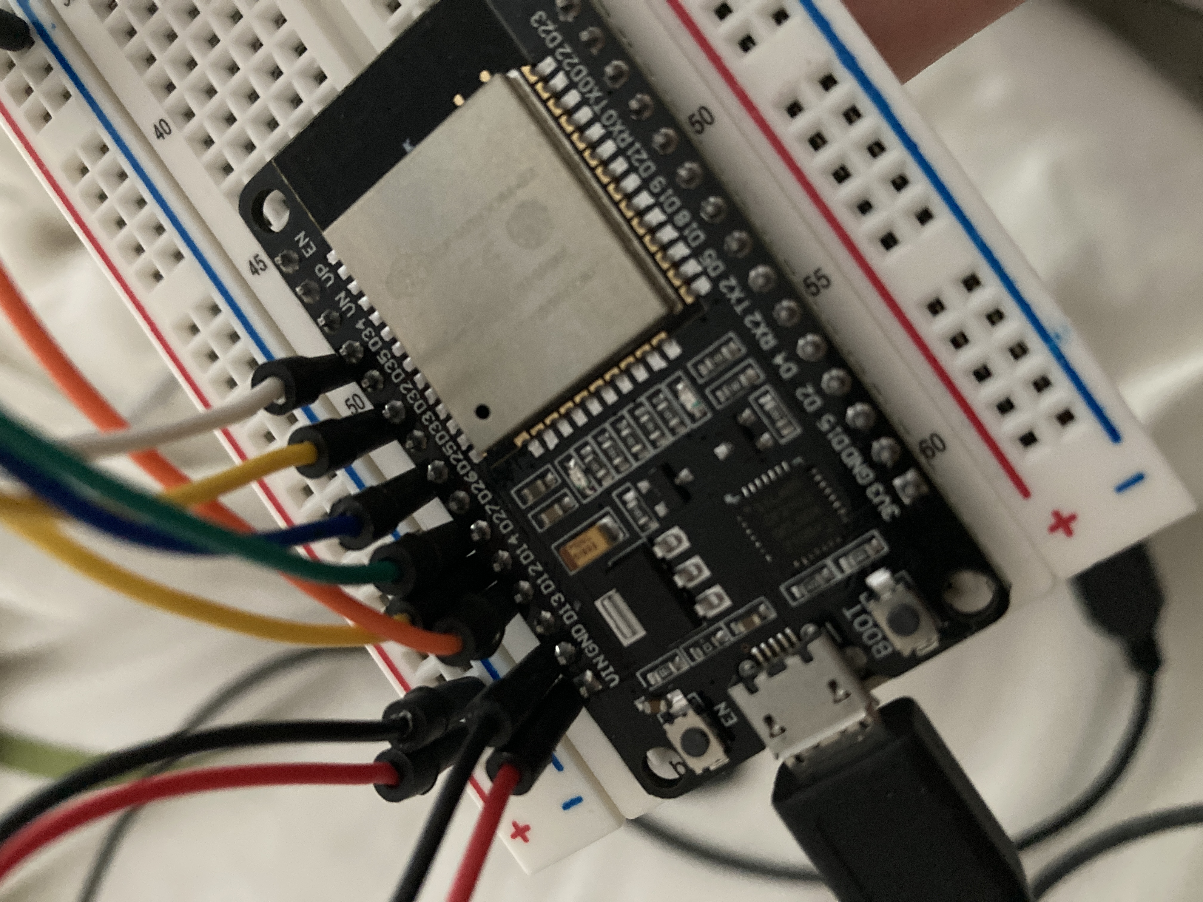
Note that Wi-Fi configuration and control can both be done from either a desktop or smart device web browser.
Upon completing the unit and powering it on for the first time, the ESP32 will create a Wi-Fi access point named "DIYnamount Config" which can be connected to without a password. Once connected open your web browser. In the address bar navigate to 192.168.4.1:81 and you will be greeted with a WiFiManager page. Search for and select your wireless network and provide credentials if necessary. When the ESP32 successfully connects to your network an LED will flash three times and stay lit before your computer or mobile device loses connection to the ESP32.
The control interface will now be accessible on any device with a web browser that is connected to the same network as the stand. Simply navigate to 192.168.1.117 (or otherwise if you changed this earlier) in your address bar. If more than one device is on the control panel at the same time the control sliders will be synchronised across both devices.
In case the connection between the stand and the network is dropped the ESP32 should be power cycled. Previous Wi-Fi credentials will be deleted so you must reconnect it to your network.
The default position of the stand should be in the middle of the speaker cone and at its closest to the speaker cone. Make sure that you move the microphone manually into this starting position before proceeding with remote control. Click the "Calibrate Controls" button to return the sliders to this default position.
As you move the sliders the microphone will also move on its rails. There are -1/+1 buttons to incrementally move the microphone if precision is necessary. The small image of an SM57 microphone displays the current real position of the microphone on the stand itself.
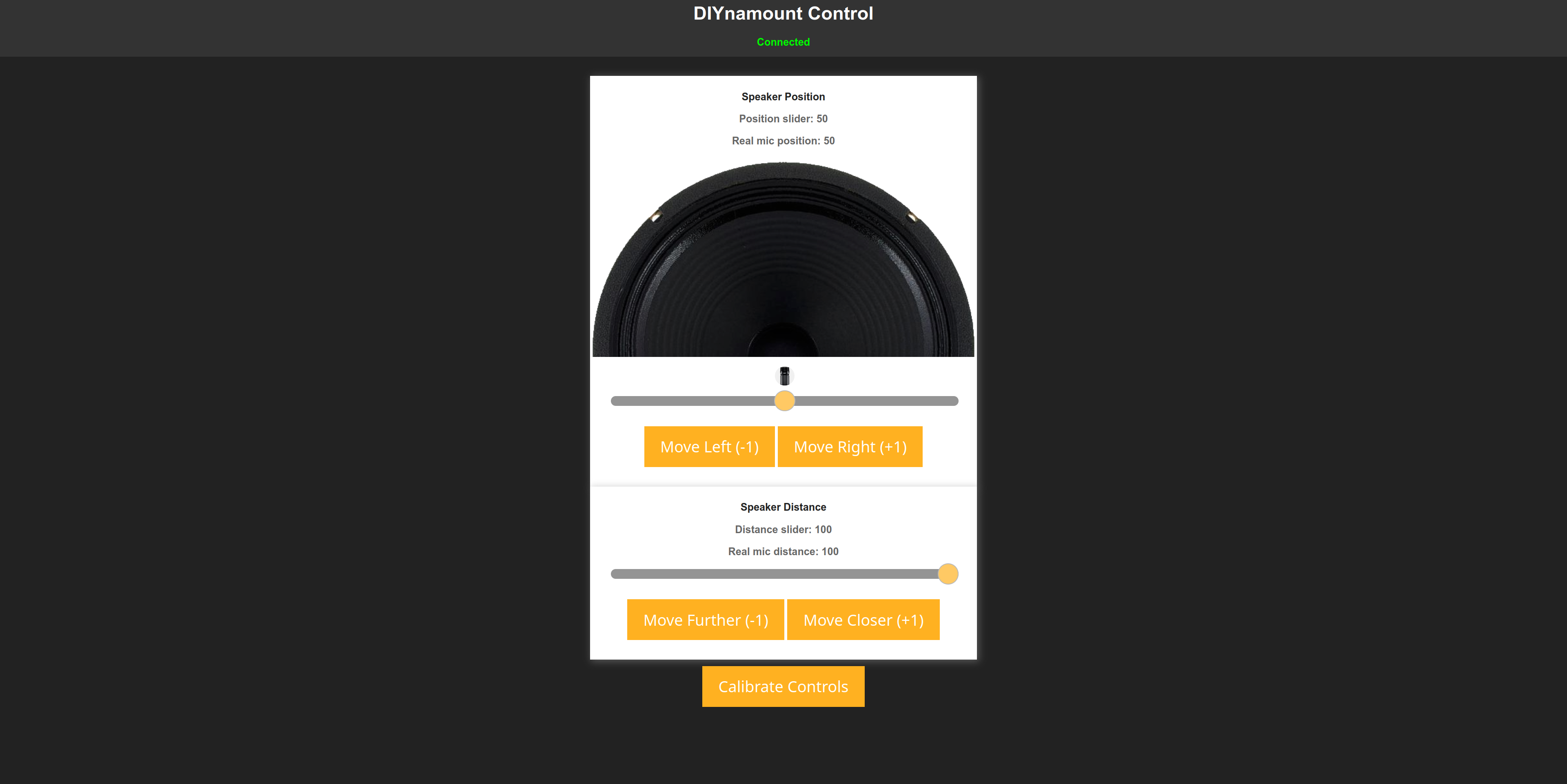
Moving the slider should be analogous to the position of the microphone on its rail. If the microphone moves too far or doesn't move far enough, the STEPSPERUNITMOVEMENT value should be modified. The MOTORSPEED value should also be increased if the motor is moving too fast and therefore not providing a smooth motion of the microphone.
- Rui Santos at https://randomnerdtutorials.com/ for his base ESP WebSocket code