Warning
This project is currently experimental. While unlikely, changes in the parts, the PCB and the case could happen. Proceed with it at your own caution!
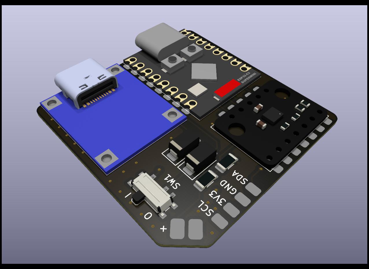
Tiny Slime aims to make the smallest possible SlimeVR trackers out of cheap and readily available modules while still preserving battery life.
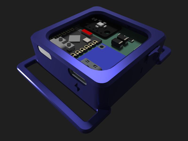
The design uses a PCB to mount the parts to, which is placed right on top of the battery for minimal height. The final case dimensions, without the strap loops end up being around 43x43x15.2 mm or 43x43x12.2 mm.
| Part | Count | Source |
|---|---|---|
| Tiny Slime PCB | 1 | JLCPCB |
| Tiny Slime Case | 1 | Print Yourself |
| Supermini ESP32C3 | 1 | AliExpress* |
| BMI shaped IMU | 1 | AliExpress |
| Unprotected USB-C TP4056 1 | 1 | AliExpress* |
| PCM12 compatible switch | 1 | AliExpress |
| SS34 diode | 2 | AliExpress |
| 1206 100k Ω resistor | 2 | AliExpress* |
| 804040 or 504040 battery 2 | 1 | AliExpress |
Tip
The case is compatible with any BMI breakout shaped module. Check out Meia's IMU store for some recommended alternatives usable on this board!
*: Link is multi-choice, pay careful attention to which you select
1: For size reasons, the PCB uses specifically unprotected TP4056 modules.
2: Battery choice is a trade-off. The 804040 should give you 800 mAh more capacity at the cost of 3 extra millimeters in height.
Components, including straps cost about $11 per tracker shipped.
Tip
These links only act as examples. They will almost certainly not be the best prices for you, as that depends on where you live and what options you have available to you. If you want to min-max the prices, do search around for better deals. Just make sure you are getting the right components!
Tip
Some components are more prone to arriving dead, like BMI160. Because of this, and just to be safe, make sure to get a few extras from everything.
Tip
Some of the links above sell items in packs, rather than individually. For example the resistors come in packs of 100. You don't need more than one of those in your cart.
Caution
Since the TP4056 module the PCB is using is unprotected, make sure to only ever pair it with a battery that comes with a protection board. Usually protected batteries have yellow tape around their top side which houses a small protection PCB. Using unprotected batteries could lead to them dying or in extreme cases catching fire or exploding.
The gerber zip file for the PCB can be downloaded from the "production" folder of the repository. This needs to be ordered from a PCB manufacturer, such as JLCPCB.
- Visit JLCPCB's site
- Hit the "Add gerber file" button and select the zip file you've downloaded
- Select the quantity of PCBs you want
- Set the PCB thickness to 0.8 and select a colour you like
Important
Some colours might incur further costs, because they are rarer. Black and green are almost always free to choose.
- For the "Remove Order Number" option, choose "Specify a location"
- Make sure PCB Assembly is ticked off
- Save the order to your cart and complete the ordering process
If you've done everything correctly, 5 PCBs should cost about $5 while 10 should cost about $7 with shipping included. You can of course choose a quicker shipping method, but the AliExpress components take more time to arrive.
Tip
It's recommended that you purchase more boards than you'd strictly need, since they are fairly cheap and mistakes can easily happen.
There are some tools that will be necessary for putting the tracker together, and there are some that are useful to have, even if not strictly necessary.
For a soldering iron, you want something temperature controlled. If you live in a country with Amazon, something like this is a good start. This same iron can be found on AliExpress for about $3, if you look for it.
If you have soldering wire that came with the iron you have, it's probably not great, but it should work in a pinch (I still recommend buying some if you can afford it). If you need to buy it new, it's probably worth looking for something thinner, 0.5-0.6 mm in diameter. This is what I generally use. You can go with leaded or lead-free, but make sure you have decent ventillation wherever you work.
Caution
There are so-called "low temperature" solder rods. These are made for plumping and are not usable for soldering electronics. If they specifically call out that you can melt them with a lighter, those are also for that purpose, avoid!
Some parts on this board are smaller than what most people are used to. To help avoid burns and to make the process easier, you should get at least a cheap set of tweezers. Something like this should work, you mainly want the ones that are either straight and sharp or bent, depends on the person, which is easier to work with.
Flux is a liquidy paste that helps solder flow better. It's mainly used when you need to rework a soldering joint after you've already created it. Theoretically it can be substituted by just adding more solder to the joint, since most solder wires contain flux, but that's not always a solution. Flux is most commonly either in the form of a pen or in the form of a syringe. This is the one I tend to use, and it worked great for me.
Caution
There are certain flux pastes that are, like the previously mentioned solder rods, made for plumbing. These are corrosive, to help with the oxidization present on pipes. You can recognize these by either reading the label, or often they look like grease (hence their other name, soldering grease). Avoid these!
When soldering, often there will be a build up of molten solder on your soldering iron. To get it off, you can use a damp soldering sponge, or a brass sponge. The former is quite a bit cheaper, you can get 5 or 10 for less than a dollar, though it will theoretically damage your soldering tip a tiny bit more than the other option. Brass sponges are more expensive, but avoids this slight damage a bit better and are generally a bit quicker to use.
In a perfect world, we don't make mistakes, but we aren't in that perfect world. When you need to desolder something, or potentially clean a pad from solder that got on it, the simplest option you have is a desoldering wick, or desoldering braid. You want something fairly thin, since that would be easier to heat up. You can start with something like this.
Although a desoldering wick is generally enough, another tool you might want to have for the job is a desoldering pump. These work by quickly sucking away molten solder. It's not as necessary for these sort of components, but it's useful in some cases. Something akin to this is what I'd go for.
Some flush cutters are needed for some *modifications* that I recommend you make for an easier soldering process. Something like this. They are fairly easy to blunt out, so you might want to buy a couple.
Multimeters can be used to check for connections, so you don't need to guess what the actual issue is. They are fairly useful even in one's day-to-day life (checking disposable batteries, checking wires in the wall, etc. etc.), so I recommend picking one up. If you do, make sure it has at the very least a continuity mode (usually denoted with a dot with waves coming out of it). This is the most necessary for checking if you have a bad connection. Something like this will certainly work, but they are also fairly cheap to buy in your local hardware store.
After working on a PCB, there might be some gunk on it left over from the soldering process. If you care for how the PCB looks, or you want to make sure you see the joints better, you might want to invest into some PCB cleaning fluid. I use this. These are almost always nasty fluids, so make sure you don't breathe them in too much.
Note
This part of the guide is incomplete. I'll update it with photos and videos of the process once I make them.
Soldering the board is a fairly simple and straightforward process, however there can be a few pitfalls that are easy to fall into if you've never done anything like this before.
The general rule of thumb is that you want to start with smaller components and slowly make your way towards the bigger components, but placement can also play a role in this.
I'll be detailing each step and in the order I recommend you do them in. If you feel like a particular component is giving you trouble, try soldering it on earlier, that way you have more space to do the operation in.
The switch is sadly the only component on the PCB I couldn't supersize. As a result, it's probably the one that requires the most accuracy.
Start by putting a tiny blob of solder on one of the side mounting pads, and then, while remelting the blob, put the component in place. This should secure it enough that you shouldn't need to worry about the switch moving while you work on the rest.
Afterwards you should continue on the other side of the switch, soldering in the other mounting pins there, before moving back onto the one you've started on and finishing the job.
Finally, solder in the three electrical pins.
To-Do: Video about soldering the switch
The resistors are so-called 1206 resistors. This means They are about 0.12x0.06 inches, or 32x16 mm in size. This is considered fairly big in terms of electronics, and it's quite simple to solder them in.
First, put a solder blob onto one pad of the resistor, then, while remelting it, gently place the resistor between the two pads. Once that's done, just solder in the other pad, and you should be done.
To-Do: Include video of soldering the resistors
Now onto the last "small" component. The diodes have one of the larger form factors available for surface mount soldering. They are very similar in technique to the resistors.
Firstly, orientation is important. Notice, how the diodes' pads have an incomplete rectangle around them. If you look carefully on the diode itself, it should have a few lines on one side. Make sure these lines are on the same side as the complete side of the rectangle.
First put solder on one pad, then while remelting it, place the diode in between the two pads, then solder in the other pad.
To-Do: Include video of soldering the diodes
This is where the fun part begins. To keep the end result as thin as possible, I opted to not use through holes when mounting the large modules in place. This makes it more of a challenge to solder them in place.
One technique that works well, even if it's a bit unorthodox is cutting off the corners of the charging module with flush cutters, giving you DIY castellations (half circle pads that are made for soldering flush). Afterwards, you can just heat the center of the pad while feeding it with solder wire, and eventually it should spread towards the TP4056's pads, connecting it to the PCB.
If you don't want to, or can't cut the corners off, you can still solder the module in place by just putting a lot of solder into the hole, but I recommend checking the end result with a multimeter, if you do so.
For the best result, make sure you align the edge of the charging module with the edge of the PCB, so the charging cable can make a good connection to it.
To-Do: Include video of soldering the TP4056
The brain of the entire tracker is fairly simple to solder, since it was made to be mounted on PCBs like this, hence the castellations on the side.
First, put a blob of solder on one of the pads, and place the module into its rectangle while remelting the joint. This probably won't result in a very strong connection, but it will be enough to not have to worry about it while you do the rest. Ideally you should then solder a pin that's further away from the one you've just soldered to give it more stability. Then go through one by one, soldering in all the joints. A good connection should make a small bridge from the PCB's pad onto the side of the Supermini. I recommend going over the original joint you've made also, just so it's secure enough.
To-Do: Include video of soldering the Supermini
The IMU is a special challenge on this board. I tried to make sure that it's as easy as possible to get it mounted on the PCB, but it's still not simple. There are several methods to go about it, which will depend on what IMU you have and what you are willing to do with it. I'll try to list them in the order of simple to difficult.
To-Do: Include videos of all three methods
Meia's store sells BMI270 modules that are made with castellations on them. These are ideal for this PCB, since those are specifically designed for this purpose.
This is the same idea as with the TP4056 module. Just go through the side with the 7 pins, and cut them in half one by one. I recommend first making a cut from the side of the hole towards the center on the longer side, and then cutting it off from the side. This way you have enough space to make the rest of the cuts also.
Afterwards it's the exact same method as for the Supermini, just go through each pin and put on enough solder until a small bridge forms from the PCB to the IMU.
This strategy I can't recommend, because it's very hit or miss. But, if you put enough solder into each hole, theoretically it should result in a solid connection eventually. The problem with this method is that you can't really see the joint, so you don't know if it's even there or not.
First start by putting a blob of solder onto one pad and placing the IMU into the rectangle while remelting it. This should keep it in place while you work on the rest.
For the remaining pins, heat the ring around the pad and just push in the solder wire, until a visible blob forms at the top. To make it more likely that a joint is formed, you can put solder on the side of the pad that comes out from under the IMU, and then quickly move between the blob at the top and the solder on the side. This gives it a better chance at connecting the two.
If you have a multimeter, it's recommended that you check the connections, once you are done, so you know if they are well-made or not.
The easiest and quickest way to solder the PCB is using solder paste and a hotplate. Although they are not expensive, these are generally unnecessary expenses on top of the other tools you already have, but if you need to solder a lot of these together, it might just be worth it.
If you are looking for an inexpensive hotplate, I can recommend this one (select the one labeled "Type1"). It's relatively small, only enough to solder one of these at a time, but for $20, it does its job well. You will need a USB-C charger for it that can deliver 65W (most modern laptop chargers can achieve this).
As for paste, almost any will do, though my recommendation is this 138C paste containing bismuth, since at those temperatures, it's unlikely that the modules on the PCB will be affected.
The method is as simple as putting small blobs of solder paste onto the pads, and then heating the hotplate 10-15 C above the melting temperature of the paste while the board is on top of it. For the modules with rows of pins on the sides, you can just draw a line across them.
This gives probably the cleanest results out of the bunch, and it works without having to first mutilate the modules by cutting pieces off of them.
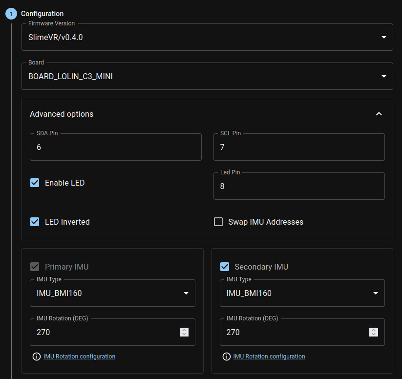
For flashing use the online firmware flasher tool made by Butterscotch. There will be a few changes you need to make to the defaults for it to work properly.
Tip
Don't want to go through the hassle? Here's a link with most of the necessary changes already done, just change the firmware version, IMU (if using anything other than a BMI160) and input your Wi-Fi credentials.
For firmware version, when running with BMI160, choose the latest stable
release. This will likely be the topmost one. At the time of writing, this is
0.4.0. If you are using BMI270, you want to select the l0ud/main option, as
this is the one that contains the necessary changes for the IMU to work.
Similarly, for LSM6DSV, you want the wigwagwent/lsm6dsv-with-bug-fix option.
For the board, you want to choose BOARD_LOLIN_C3_MINI.
Open Advanced options, change SDA Pin to "6", SCL Pin to "7", and Led Pin to "8". The rest of the options should stay default.
For primary and secondary IMU, select the one you have. The rotation value shouldn't matter if you use Automatic Mounting Calibration in the server.
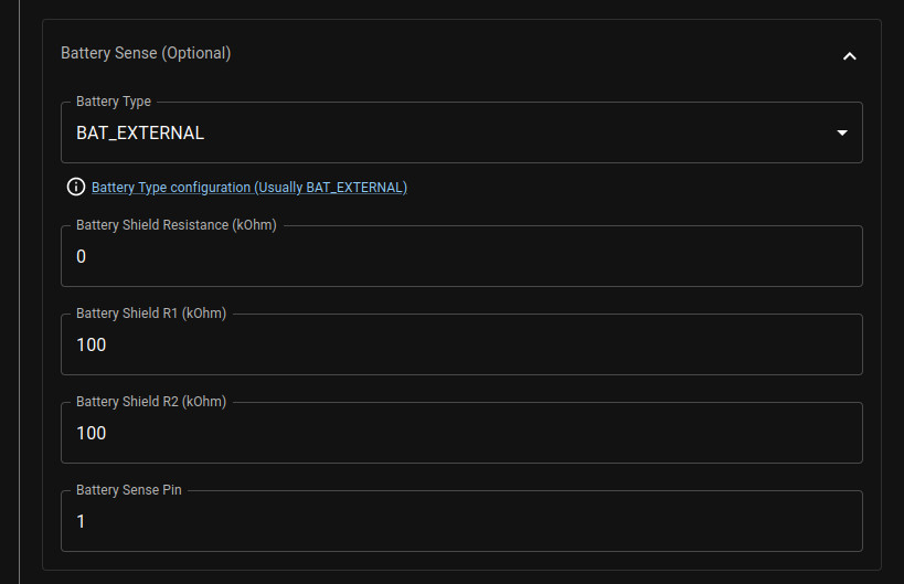
Now open up the Battery Sense section, select battery type as BAT_EXTERNAL,
put "0" as the battery shield resistance, and 100 for both battery shield R1 and
R2. Also change the battery sense pin to "1".
Note
At this time the battery sense won't work quite correctly for this board because of a bug. A fix for this issue is already in the works waiting to get accepted.
Now open up the Wi-Fi settings section and input your 2.4GHz Wi-Fi's credentials.
After you've done this, it's time to plug in the Supermini. To make sure it's flashable, first double check that it's turned off, then hold down the left button on it labeled "BOOT", and while holding it down, plug it into your PC. Some units have some preflashed software on them, for example it might blink the LED on-board. If it starts doing that, that means you didn't do the previous step properly, try again.
After flashing you need to manually reset the Supermini. This can be done by either hitting the reset button (the one on the right labeled "RST") or by just unplugging it and powering it on. If everything went well and your SlimeVR server is turned on, it should be able to connect and appear in there.
To-Do
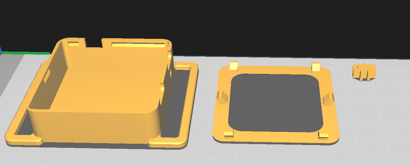
The case is made up of 3 parts, a bottom, a top and a switch extender. These were designed to not require any support, or brim when printing them, though some mouse ears can help, if you experience warping around the strap loops.
The ideal orientation of the parts is the following:
I recommend printing the switch at the very least separately, since it's quite small, so slowing down the printing might help you get a more accurate print.
The following print settings worked well for me, but feel free to experiment with them:
- Layer height: 0.2 mm
- Line width: 0.4 mm
- Wall line count: 4
- Infill pattern: Cubic*
- Infill density: 10%*
- Supports: off
- Build plate adhesion: none
*: There's barely any parts of the case that are thick enough to require infill, so don't stress about this much.
To-Do: include a video of the assembly process
After printing, first slide the USB-C ports into the corresponding holes at an angle and then push the other end of the battery and PCB into the case. Afterwards take the printed switch extender and slide it onto the switch on the PCB. Finally, snap the lid on. If you can't easily to this last step, try first aligning one side of the lid into the corresponding holes and then rotate it into place, snapping the holders in as they meet the edge.
