- Name: FourteenSegDisplay
- Description:
- A library for the Arduino eco-System to display data on a 14 segment LED module.
- It requires 2 or 3 Daisy chained shift registers.
- Common anode and common cathode support.
- Supports ASCII font, Hexadecimal, Decimal point, strings.
- Optimized low memory footprint.
- Manual setting of segments to any user defined pattern supported.
- Also support seven, nine and sixteen segment displays.
- Author: Gavin Lyons.
The library is included in the official Arduino library manger and the optimum way to install it is using the library manager which can be opened by the manage libraries option in the Arduino IDE. Search "fourteen" in search bar of library manager to find it quickly.
See link below for instruction for this and for the other installation methods too.
Installing Additional Arduino Libraries guide
The four different fonts are in 4 different files. I have kept the cpp files separate in the interests of modularity, ease of hardware setup testing and to keep each program use case as small as possible. So in essence this library is four separate libraries packaged in one. The TEST.ino files contains a set of tests demonstrating library functions.
Files table
| Segment | Example files | Font file | Header file | Cpp code file |
|---|---|---|---|---|
| 7 | SevenSegDisplay_TEST.ino SevenSegDisplay_SCROLL.ino | SevenSegDisplayFont.h | SevenSegDisplay.h | SevenSegDisplay.cpp |
| 9 | NineSegDisplay_TEST.ino | NineSegDisplayFont.h | NineSegDisplay.h | NineSegDisplay.cpp |
| 14 | FourteenSegDisplay_TEST.ino FourteenSegDisplay_ADC.ino | FourteenSegDisplayFont.h | FourteenSegDisplay.h | FourteenSegDisplay.cpp |
| 16 | SixteenSegDisplay_TEST.ino | SixteenSegDisplayFont.h | SixteenSegDisplay.h | SixteenSegDisplay.cpp |
Library Functions
The commented functions can be found in library header files Display.h. See these file for more details on functions.
- SevenSegDisplay(uint8_t rclk, uint8_t sclk, uint8_t data, bool common, bool transistors);
- NineSegDisplay(uint8_t rclk, uint8_t sclk, uint8_t data, bool common);
- FourteenSegDisplay(uint8_t rclk, uint8_t sclk, uint8_t data, bool common, bool model2, bool model3);
- SixteenSegDisplay(uint8_t rclk, uint8_t sclk, uint8_t data, bool common, bool nodecpoint);
- void displayBegin(void);
- void displayASCII(uint8_t ascii, uint8_t digits); // 7 9 and 14 seg only
- void displayASCIIwDot(uint8_t ascii, uint8_t digits ); // 7 9 and 14 seg only
- void displayASCII(uint8_t ascii, uint8_t digits , bool dotOn); // 16 seg only
- void displayHex(uint8_t hex, uint8_t digits ;
- void displaySeg(uint16_t value, uint8_t digits);
- void displayString(const char* str, uint8_t startPos); // Not available in Model1 14 seg
Display segments layout.


A seven-segment display is a form of electronic display device for displaying decimal numerals. Seven-segment displays are widely used in digital clocks, electronic meters, basic calculators, and other electronic devices that display numerical information. The first shift register sets the eight bits of segment data ((DP)gfedcba) and the second controls the digits. Tested on a 2381AS 3 digit common anode. Will also work with common cathode. (note change transistor for NPN and emitter to GND). If user wants to switch the digits without transistors they can use the "transistors" parameter in the object constructor, NB: do not exceed current limit on pin of the controller by using large values of resistors on segments. The calculation will be depend on the MCU's and Display module used.
The design supports maximum eight digits, Just add more digits to rest of shift registers pins in order. D8D7D6D5D4D3D2D1 - For purposes of the schematic and software D1 is the Least significant or right most Digit.
There are two example files for seven segment, TEST shows the various different functions, SCROLL shows how to do scroll text.

Connections
| Arduino , SW | IC 1 | IC 2 | 2381AS |
|---|---|---|---|
| GPIO , SCLK 595 | SCK | SCK | |
| GPIO , RCLK 595 | RCK | RCK | |
| GPIO , SER 595 | SER | ||
| QH' | SER | ||
| QA | a 11 | ||
| QB | b 7 | ||
| QC | c 4 | ||
| QD | d 2 | ||
| QE | e 1 | ||
| QF | f 10 | ||
| QG | g 5 | ||
| QH | DP 3 | ||
| QA | D1 8 | ||
| QB | D2 9 | ||
| QC | D3 12 | ||
| QD-QH | D4-D8, 5 Extra digits as needed |

It is an extension of the more common seven-segment display, having an additional two segments. It provides an efficient method of displaying alphanumeric characters. The nine segment display is by far the rarest and least used of the four display types supported in library. There are a few variants of it.
- The two extra segments are forward slashes
- The two extra segments are back slashes
- The two extra segments are vertical
- Mixed, Mixed vertical and slashes, mixed forward and backward slashes
Only 1 and 2 are commercially available at present as far as I know. The font included supports number one only, as it most common and defined. The others will work with code but font file will need some adjustment for some characters.


Connections
Six bits digits control D6D5D4D3D2D1. + 10 bits of segment control (DP)ihgfedcba. A total of 16 bits sent to Module thru two shift registers. This design supports a maximum of 6 digits. For purposes of the schematic and software D1 is the Least significant or right most Digit.
| Arduino , SW | IC 1 | IC 2 | Nine segment module |
|---|---|---|---|
| GPIO , SCLK 595 | SCK | SCK | |
| GPIO , RCLK 595 | RCK | RCK | |
| GPIO , SER 595 | SER | ||
| QH' | SER | ||
| QA | a | ||
| QB | b | ||
| QC | c | ||
| QD | d | ||
| QE | e | ||
| QF | f | ||
| QG | g | ||
| QH | h | ||
| QA | I | ||
| QB | DP | ||
| QC | D1 | ||
| QD | D2 | ||
| QE | D3 | ||
| QF | D4 | ||
| QG | D5 | ||
| QH | D6 |

A fourteen-segment display (FSD) sometimes referred to as a Starburst, Alphanumeric or Union Jack display. is a type of display based on 14 segments that can be turned on or off to produce letters and numerals. It is an expansion of the more common seven-segment display, having an additional four diagonal and two vertical segments with the middle horizontal segment broken in half. A seven-segment display suffices for numerals and certain letters, but unambiguously rendering the ISO basic Latin alphabet requires more detail.
The library requires two or three daisy chained shift registers. The module that lib was tested on is a two digit LDD-F5406RI common cathode module. Library is also designed to work with common anode(If using common anode the transistors PNP will have to switch Digit pin to VCC (not GND as per schematic) to activate. Library includes ASCII font and also supports Strings, Hexadecimal, Decimal point. Optimized low memory footprint. It also provides a function for manually setting segments to any user defined pattern.
There are three different designs(models) The main example file(FourteenSegDisplay_TEST) covers all three models, The second file (FourteenSegDisplay_ADC), shows a practical example using Model2 to display a ADC value on display. The library was tested on a two digit LDD-F5406RI common cathode.
I recommend Model 2 rather than 1, less GPIO used and more Software functions. Model 3 is just for users who only have 1-2 digits in project and do not need Decimal point(they can still control it form outside library with an extra GPIO).
Models Table comparison
| Model | No of Shift registers | No of GPIO pins | No of digits |
|---|---|---|---|
| 1 | 2 | 3+ N (N = Number of digits) | 1 to infinity |
| 2 | 3 | 3 | 1 to 8 |
| 3 | 2 | 3 | 1 to 2 (no decimal point) |
Model One
This model uses GPIO to switch on and off digits as a result it uses more GPIO pins than model 2. It requires (3+N) Digital GPIO pins, where N is number of digits used. So 4 digits requires 7 GPIO + common ground. This model needs two shift registers.
Connections
Note: N is number of digits (eg for eight digits (D8D7D65D4D3D2D1). For purposes of the schematic and software D1 is the Least significant or right most Digit. If adding more modules or larger modules simply add another GPIO for each digit. and connect data lines together(a to a , b to b etc) You can add as many digits as you want.
| Arduino , SW | IC 1 | IC 2 | LDD-F5406RI |
|---|---|---|---|
| GPIO , SCLK 595 | SCK | SCK | |
| GPIO , RCLK 595 | RCK | RCK | |
| GPIO , SER 595 | SER | ||
| QH' | SER | ||
| QA | a 12 | ||
| QB | b 10 | ||
| QC | c 9 | ||
| QD | d 7 | ||
| QE | e 1 | ||
| QF | f 18 | ||
| QG | g1 13 | ||
| QH | g2 6 | ||
| QA | h 17 | ||
| QB | j 15 | ||
| QC | k 14 | ||
| QD | l 2 | ||
| QE | m 4 | ||
| QF | n 5 | ||
| QG | DP 8 | ||
| GPIO, D1 | Digit 1 11 | ||
| GPIO, D2 | Digit 2 16 |

Model Two
This model uses a third shift register to switch on and off digits as a result it uses just 3 GPIO pins + common ground. The disadvantage is it requires a third shift register and has a maximum of 8 digits.
Connections
This model supports a maximum of 8 digits (eg for eight digits (D8D7D65D4D3D2D1). For purposes of the schematic and software D1 is the Least significant or right most Digit. The table below can be expanded by 6 more digits if more LED modules added for digits 3-8.
| Arduino , SW | IC 1 | IC 2 | IC 3 | LDD-F5406RI |
|---|---|---|---|---|
| GPIO , SCLK 595 | SCK | SCK | SCK | |
| GPIO , RCLK 595 | RCK | RCK | RCK | |
| GPIO , SER 595 | SER | |||
| QH' | SER | |||
| QH' | SER | |||
| QA | a 12 | |||
| QB | b 10 | |||
| QC | c 9 | |||
| QD | d 7 | |||
| QE | e 1 | |||
| QF | f 18 | |||
| QG | g1 13 | |||
| QH | g2 6 | |||
| QA | h 17 | |||
| QB | j 15 | |||
| QC | k 14 | |||
| QD | l 2 | |||
| QE | m 4 | |||
| QF | n 5 | |||
| QG | DP 8 | |||
| QA | Digit1 11 | |||
| QB | Digit2 16 | |||
| QC-QH | 6 extra digits as needed |

Model Three
Model 3 is just for users who only have 1-2 digits in project and do not need Decimal point. It uses the last two digits of the second shift register to switch the two digits So same as Model 2 except for these two bits at end and one less shift register. So it sends out two data bytes as abcdefg1g2hjklmnD1D2.
| IC 2 | LDD-F5406RI |
|---|---|
| QG | Digit1 11 |
| QH | Digit2 16 |
A sixteen-segment display (SISD) is a type of display based on 16 segments that can be turned on or off to produce a graphic pattern. It is an extension of the more common seven-segment display, adding four diagonal and two vertical segments and splitting the three horizontal segments in half.

This design requires 3 shift registers. 2 shift registers move data word to display and third to controls digits. The last bit of third register controls decimal point. As a result this limits maximum display size to seven digits but If user does not want decimal point support this can be disabled by setting a parameter. and user can use all 8. This model supports a maximum of 7-8 digits (eg for eight digits (D8D7D65D4D3D2D1). For purposes of the schematic and software D1 is the Least significant or right most Digit. This library was tested on a single digit PSC05-11SURKWA common cathode(schematic) and a PSA08-11EWA common anode.
Note:If only using a single digit it is possible to use two shift registers without a software change albeit without Decimal point, simply hard wire the single digit common to VCC or GND depending on Common anode or cathode and do not wire up third register and it will work.
This table can be expanded to 7-8 digits.
Connections
| Arduino , SW | IC 1 | IC 2 | IC 3 | PSC05-11SURKWA |
|---|---|---|---|---|
| GPIO , SCLK 595 | SCK | SCK | SCK | |
| GPIO , RCLK 595 | RCK | RCK | RCK | |
| GPIO , SER 595 | SER | |||
| QH' | SER | |||
| QH' | SER | |||
| QA | a 1 | |||
| QB | b 18 | |||
| QC | c 16 | |||
| QD | d 13 | |||
| QE | e 10 | |||
| QF | f 9 | |||
| QG | g 8 | |||
| QH | h 4 | |||
| QA | k 3 | |||
| QB | m 2 | |||
| QC | n 17 | |||
| QD | p 15 | |||
| QE | r 14 | |||
| QF | s 6 | |||
| QG | t 7 | |||
| QH | u 5 | |||
| QA | Digit1 11 thru a transistor npn switch | |||
| QB-QG | extra digits as needed | |||
| QH | Decimal point 12 |

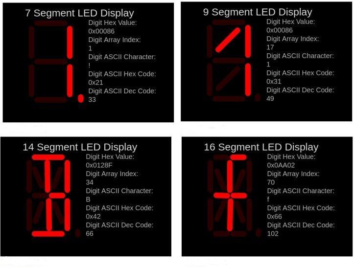
LED Segment Display Simulator character/pattern creator
- Tested on following MCUs
- Arduino UNO & NANO v3
- ESP8266
- STM32 STM32F103C8T6 "blue pill"
- ATtiny85
- ESP32
