This project allows you to create a controller for IoT devices using the AZ-Delivery AZ-Touch kit (buy it here) using one of the supported boards (here or here).
- Support for both Wemos D1 Mini and ESP32 Dev Kit C
- Light and dark mode available
- Portrait or landscape orientation
- Easily configurable via json file
- Customizable icons
- Up to 8 colors available for device statuses (ESP32 Dev Kit C only)
- And much more to come...
- AZ-Delivery AZ-Touch (https://www.az-delivery.de/en/products/az-touch-wandgehauseset-mit-touchscreen-fur-esp8266-und-esp32) kit
- Wemos D1 Mini (https://www.az-delivery.de/en/products/d1-mini) or ESP32 Dev Kit C (https://www.az-delivery.de/en/products/esp32-developmentboard) board
- An empty SD card (or micro SD with adapter) with a maximum size of 2 GB
- Arduino IDE
- An MQTT client capable of returning a list of devices and their statuses or commands (see below)
If not already present, add the appropriate url for your board in the Additional URLs for Board Manager field in the Arduino IDE Settings:
- http://arduino.esp8266.com/stable/package_esp8266com_index.json for Wemos D1 Mini
- https://dl.espressif.com/dl/package_esp32_index.json for ESP 32 Dev Kit C
Make sure that all of the following files to include (from their respective libraries) are present on your system, or (re)install the libraries using the standard procedure (via the Library Manager or by downloading the .zip):
- Arduino.h
- ArduinoJson.h
- ESP8266WiFi.h (only for Wemos D1 Mini)
- FS.h
- ILI9341_SPI.h (only for Wemos D1 Mini)
- MiniGrafx.h (only for Wemos D1 Mini)
- PubSubClient.h
- Regexp.h
- SD.h
- simpleDSTadjust.h
- SPI.h
- SPIFFS.h
- TFT_eSPI.h (only for ESP32 Dev Kit C)
- WiFi.h (only for ESP32 Dev Kit C)
- XPT2046_Touchscreen.h
Also, if you're using the ESP32 Dev Kit C board, be sure to put the User_Setup.h file provided with this repository in the TFT_eSPI library folder, replacing the original: it already contains the correct pins for your board.
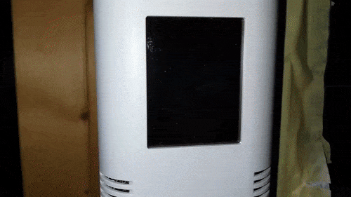
Solder the headers and assemble the necessary components as indicated in the kit quick start guide (manual is the same for both 2.4" and 2.8" versions).
In addition, you'll need to add some headers and wiring for the SD card reader, which is not shown in the device guide. Take the following pics for reference:


Basically, if your board is a Wemos D1 Mini (it fits in the small slots) you'll need to solder SD reader wirings into the empty connectors of the ESP32 slot; conversely, if your board is an ESP32 Dev Kit C (fits in the large slot), you'll solder the cables into the free connectors of the small slot.
Refer to your board pinout to identify SCK, MISO, MOSI and CS pin position. With the help of a multimeter, find the corresponding pins in the free slot (these pins are directly connected between the large slot and the small slot) and solder. The images show the correct connection, but don't consider it enough. Please double check using the multimeter in continuity mode to be sure what you're doing. I'm not responsible for incorrect wiring.
Finally, mount the TFT screen over its headers and tighten the screws: your hardware is now ready!

The main configuration is done via a json file. Copy the config.sample.json file available in this repository, save it to an SD card and rename it to config.txt; now change the parameters contained in it according to your needs.
You can also use the generator at https://apps.francescorega.eu/aztouch, filling in the corresponding fields and saving the returned code.
The configuration file consists of five main sections:
Here you can configure the connection to your local network.
"wifi": {
  "ssid": "ssid",
  "password": "password",
  "ip": "127.0.0.1",
  "gateway": "127.0.0.1",
  "subnet": "255.255.255.0",
  "dns": "127.0.0.1"
}- ssid: This is the name of your local wifi network. Please note: maximum length supported: 32 characters.
- password: This is the password to allow connection to your local network. Please note: maximum length supported: 64 characters.
- ip: If you want to assign a static IP to your device you can enter it here.
- gateway: If you've configured a static IP, you must enter your gateway address here.
- subnet: If you've configured a static IP, you must enter the subnet mask here.
- dns: If you're having trouble connecting to the world wide web, enter a public DNS server address here (e.g. Google's, 8.8.8.8).
Here you can configure the connection to the MQTT broker to which the devices you want to control are connected.
 "mqtt": {
  "host": "127.0.0.1",
  "user": "user",
  "password": "password"
}- host: This is the IP address or hostname of the server on which the MQTT broker is listening. The port used for the connection is always the standard 1883 one. Please note: maximum length supported: 32 characters.
- user: This is the username used to authenticate to the broker if needed. Please note: maximum length supported: 64 characters.
- password: This is the password used to authenticate to the broker if needed. Please note: maximum length supported: 64 characters.
Here you can uniquely configure the device to distinguish it from any other similar ones on the network.
 "device": {
  "id": "1"
}- id: This must be a numeric id of your choice different from any other id used in devices with this same code on the same network. Please note: maximum length supported: 8 characters.
Here you can configure the settings for time synchronization on your device
"time": {
  "utcOffset": 0,
  "ntpServer": "your.ntp.server"
}- utcOffset: An integer representing the difference in hours between your local time and UTC.
- ntpServer: This is the NTP server to connect to for time synchronization. Choose one geographically as close to you as possible for better accuracy. Please note: maximum length supported: 32 characters.
Here you can configure the appearance of your device's screen.
"screen": {
  "landscape": true,
  "darkMode": true,
  "maxColsLandscape": 1,
  "maxRowsLandscape": 1,
  "iconsSize": 1,
  "timeout": 1,
  "headerHeight": 1
}- landscape: A boolean value. Define whether your screen is in landscape (true) or portrait (false) mode.
- darkMode: A boolean value. Define whether your screen should use the dark (true) or light (false) color set.
- maxColsLandscape and maxRowsLandscape: Integers indicating respectively the maximum number of columns and rows used by the display grid when the device is in landscape mode. If used in portrait mode, these two values will be automatically swapped.
- iconsSize: An integer representing the length in pixels of the side of each icon displayed on the screen (icons must be square).
- timeout: An integer representing the number of seconds after which the backlight will turn off if no action is taken.
- headerHeight: An integer representing the height in pixels of the header bar containing the title, time and signal quality.
This is the main element of the configuration. An array containing an object for each type of device that you want to manage (e.g. an object for sockets, an object for lights, an object for curtains, etc.).
"iot": [
  {
   "name": "Object name",
   "icon": "icon-name",
   "topic": {
    "listRequest": "/Your/Topic/Here",
    "listResponse": "/Your/Topic/Here",
    "statusRequest": "/Your/Topic/Here",
    "statusResponse": "/Your/Topic/Here"
   }
  },
  {
    ...
  }
]
Each object contained in the array will contain the following properties:
- name: The name assigned to the type of device that will be displayed on the screen. Please note: maximum length supported: 32 characters.
- icon: The name of the icon to be associated with the type of device displayed on the screen, chosen from those available in the icons.cpp file.
- topic: An object containing in turn the following properties:
- listRequest: The topic that will be called when a device type is selected from the home screen. There must be some client listening capable of returning, upon receipt of this topic, a list of all devices of that type and their current status (e.g. a list of all the sockets connected to the broker and their status). Please note: maximum length supported: 64 characters.
- listResponse: The topic in which the list of devices generated in the previous point will be published and to which this controller will have to subscribe to stay listening.
- statusRequest: The topic that will be called when a device is selected from the devices screen. There must be some client listening capable of returning, upon receipt of this topic, a list of all available commands for that device and their topics (e.g., for a socket, the commands to set the on and off statuses with the related topics). If you need to use the device identifier in the topic, you can enter %s and it will be automatically replaced when needed. Please note: maximum length supported: 64 characters.
- statusResponse: The topic in which the list of available commands generated in the previous point will be published and to which this controller will have to subscribe to stay listening.
When you're done with the changes, make sure to save the file to the card with the correct name and, if necessary, minify it to save space. Your configuration is ready!
Additional advanced configuration is available through the variables in the advancedconfig.cpp file. Normally you won't need to change them, so only edit this file if you really need to and you know what you're doing.
The advanced configuration variables are:
- StartRule: A struct for the simpleDSTadjust library that defines when daylight saving begins. It contains six elements: the code of the time zone (e.g. "CEST"), in which week of the month the change takes place (e.g. Last), in which day of the given week the change takes place (e.g. Sun), in which month the change takes place (e.g. Mar), at what time the change takes place (e.g. 2), how many seconds the solar time is changed (e.g. 3600).
- EndRule: Opposite of the previous one, and with the same parameters, it defines when daylight saving time ends.
- configSize: The size, in bytes, of your configuration file, used to allocate the necessary memory. Make sure you always leave some extra space for this.
- mqttSize: The size, in bytes, of the longest message your device will receive via MQTT, used to allocate the necessary memory.
- maxDevices: The maximum number of devices of the same type that can be managed by this device.
- maxDeviceTypes: The maximum number of different device types that can be managed by this device.
- maxDeviceStatuses: The maximum number of different commands that can be associated with a single IoT device.
- filename: The name of the configuration file on your SD card.
- DEVICE: The name of this device, used, together with the id configured in the json file, in the connection to the broker and in the system topics.
- DELIMITER: The character that separates the different parts of the MQTT topics
- debug: A boolean value. When true, messages relating to the various actions performed will be written to the serial monitor.
The parameters of the screen json object in the main configuration file can also be modified via MQTT topic. Simply publish a message on a topic consisting of the name of your device, its id, the string "Config" and the name of the property to be modified separated by the configured delimiter, and assign it as payload the new value you want to set.
For example, if you haven't modified the advanced configuration file (thus keeping the default values of DEVICE and DELIMITER), you'll have a topic like /TouchController/1/Config/landscape and in this case its payload can be true or false.
You'll also be able to delete the calibration file via the deleteCalibration property (e.g. /TouchController/1/Config/deleteCalibration): in this case, upon reboot, you'll be prompted to recalibrate the touchscreen.
This repository includes a default set of icons for your devices. You can change it according to your needs by editing the src/icons.cpp file. Just make sure you keep two icons as back and next, as they're used for pagination. Remember that all icons must be the same size, set in the configuration file.
To add an icon, first download it in the correct format (for example, if you want to get an image from Font Awesome you can use https://fa2png.app); then get its xbm content via https://convertio.co/it/png-xbm; finally add it to the myIcons array and insert its name in the iconNames array. Pay attention: the image must be square, with a side length equal to the value set as iconSize in your configuration file.
When you're done with the necessary configurations, you're ready to upload your code to the board.
Select the correct board from the Tools > Board menu according to your needs:
- ESP32 Arduino > Esp32 Dev Module for ESP32 Dev Kit C
- ESP8266 Boards > LOLIN(WEMOS) D1 R2 & mini for Wemos D1 Mini
Select the correct port and upload: when the uploading is finished, your device will start automatically, trying to load the first configuration.
For the first start, insert the SD card containing your previously created configuration file; wait until the copy is finished, then you can safely remove it.
After this you'll be shown the calibration screen, asking you to tap two points on the screen, to correctly detect subsequent touches.
At this point you've arrived at the home screen (subsequent starts will start directly from here): a grid of the set size will contain the different types of devices, with their name and relative icon, if available.

When a device type cell is touched, a message with an empty payload will be sent to the corresponding listRequest topic. At this point, a client listening somewhere on your network will have to process a list of devices of that type with their id and name and, optionally, also icon and color; these data must then be published on the listResponse topic in the form of json array, as in the following example:
[
  {
    "id": 1,
    "name": "your-device",
    "color": "your-color",
    "icon": "your-icon"
  },
  {
    ...
  }
]
Here, id should be a unique numeric identifier of that device on the network; name is the name of the device that will be displayed on the screen; color is the background color that will be assigned to the device cell; icon is the name of the icon that represents the device.
Pay attention: color must be chosen among the colors available in the file icons.cpp (black, white, blue, yellow, green, red, pink, cyan), and anyway it will work only on ESP32 Dev Kit C boards; if an unavailable color, or no color, is chosen, or if you're using a Wemos D1 Mini board, no color will be shown in the cell.
Pay attention: icon must be chosen among the icons available in the file icons.cpp; if an unavailable icon, or no icon, is chosen, the generic one for the device type (defined in the configuration file) will be used, if any. If not available, no icon will be shown.
The data in this json will be used to build the second level page, containing the cells with the different devices of that type.

When a device cell is touched, a message with an empty payload will be sent to the corresponding statusRequest topic. If the string %s is present in the topic, it will be automatically replaced with the right device id. At this point, a client listening somewhere on your network will have to process a list of all the commands available for that device, with their name, topic and payload to recall them; these data must then be published on the statusResponse topic in the form of json array, as in the following example:
[
  {
    "name": "Your command",
    "topic": "/Your/Topic/Here",
    "data": "your-payload-here"
  },
  {
    ...
  }
]
Here, name is the name of the specific command (e.g. on or off when device is a socket); topic is the topic to post to to invoke that command; data is the payload of the message published on topic.
The data in this json will be used to build the third level page, containing the cells with the different commands available for that device.
By touching one, a message with the associated payload will be published on the relevant topic and a confirmation screen will appear, before returning to the home screen.
If only one command is given, with no topic, but only data, no message will be sent, but instead the value of data will be shown on the screen. This is useful for read-only devices: think, for example, of a smart thermometer, to which you cannot send commands, but only have to read the temperature.


In any screen, after a period of inactivity (set as screen > timeout in the configuration json file), the system will turn off the backlight and return to the home screen.
Please note: this is just an explanation of how this device works and what data it expects. How to set up your listening client depends on your needs and is beyond the scope of this guide; just make sure the returned data is in the correct format.
If you want more practical information you can also take a look at the examples, where available.
The AZ-Touch kit case perfectly contains its PCB, display and your board; despite this, due to its size, the SD card sticks out from the container. For this reason, this code is designed to need the SD card only at the first configuration. If you still want to keep the card inserted, you'll need to manually make a change to the container, as explained in this post: https://www.az-delivery.de/blogs/azdelivery-blog-fur-arduino-und-raspberry-pi/arduitouch-4-nutzung-des-card-reader.
Please note that I'm not responsible for malfunctions due to this operation.
When uploading the code, on ESP32 Dev Kit C, it sometimes happens that the board looks stuck: in this case, hold down the Boot button until the code actualy starts uploading.
If an SD card is inserted, on Wemos D1 Mini, the board may occasionally mistakenly detect fake touches on the TFT display: if this happens, please restart the board and remove the card, as there's no reason to leave it inserted.
While saving calibration, on Wemos D1 Mini, the board will restart with a "Cannot write to calibration file" error. Despite this, writing will be successful and all data will be saved in the calibration file.
If you encounter an unreported problem, please report it by opening an issue. Use the appropriate debug mode and tools (e.g. MQTT Spy to check MQTT communications, ESP Exception Decoder to interpret the board errors) and write all the data in your report, specifying what you expect, what happens, which card you use and what error messages you received, if any. I'll get back to you as soon as possible.
If you want to contribute to the project, you're welcome: open an issue explaining your idea and its development will be evaluated, or create the code changes yourself and open a pull request when you've done.
Please note that this code is provided "as is", and it's not guaranteed to be bug free - I do my best to keep it up to date in my spare time.
Except for the TouchControllerWs files, which have been modified from those available in the ThingPulse esp8266-weather-station-color project, and for the User_Setup file from the TFT_eSPI library, the code for this repository is made by me and is distributed under the MIT license.
Finally, also note that I created this code in a personal capacity and I'm no way affiliated with AZ-Delivery.
Thanks for taking an interest in AZ-Touch IoT Controller!