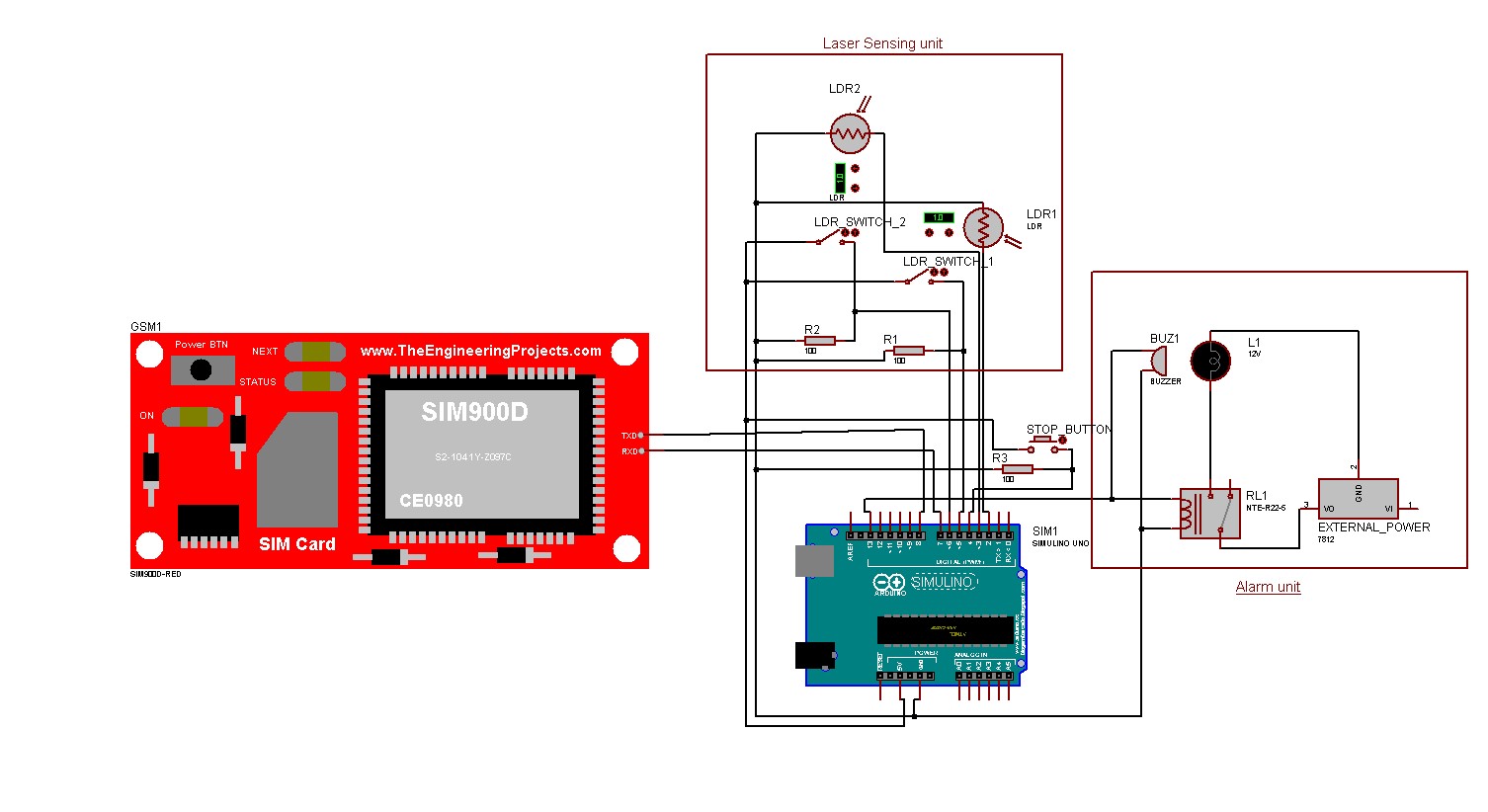
This is a simple project to control a laser security system with Arduino. The laser is controlled by an ATmega32 which enables the laser to blink at a certain rate. This laser is sensed by an LDR sensor from the other end and detects the rate at which the laser blinks. The LDR sensor is connected to the Arduino which controls the alarm system. Whenever someone interrupts the laser, the Arduino does the following:
- Turns the buzzer on
- Turns the red light on
- Sends an SMS to the owner
- Calls the owner
The alarm can be turned off by pressing the push button on the Arduino. There are switches to turn off the security of any specific edge of the boundary. Watch the demonstration of the project here.
- Arduino (Recommended - Arduino Uno)
- ATmega32
- GSM module (Recommended - SIM900)
- Laser
- LDR (Recommended - LDR module)
- Buzzer
- Red light
- Relay module
- Push Button
- SPST swithches
- Power adapter (output 5V, 2A)
- USB cable
- Wires
-
Download the project.
-
Open the Arduino IDE, connect your Arduino to your computer and upload the sketch laser_security_system.ino.
-
Now connect the following components to the Arduino as follows:
-
LDR:
D0of LDR1 (LDR module) topin 3.D0of LDR2 topin 2.VCCs of both the LDRs to Arduino's5V.GNDs of both the LDRs to Arduino'sGND.Note: The LDR connection described above is for LDR module. For more details, see the documentation. -
Buzzer:
VCCtopin 13andGNDto theGNDof Arduino. You can also connect it to the relay if you want a better buzzer that requires higher voltage. -
Red Light: Relay modules'
INtopin 13parallely with buzzer.VCCandGNDof the relay module should be connected to Arduino's5VandGND.COMof the relay module to external power's+end and theNCof the relay module to the red light's+end. The red light's-end should be connected to the-end of the external power directly. For more details, see the documentation. -
Push Button One end of the stop button (push button) to
pin 4and the other end to the5Vpin. Note that the end which is connected to pin 4 must be connected with a pull-down resistor as shown in the image below. -
Switches: One end of both the SPST switches should be connected to the
5Vof Arduino and the other ends topin 5andpin 6. These also require pull-down resistors as like as the push button. -
GSM module:
TXpin of the GSM module topin 8andRXpin of the GSM module topin 7.GNDof the GSM module toGNDof Arduino. The power port'sVCCandGNDof the SIM900 should be connected to theVCCandGNDof the adapter.Note: The GSM module requires the current supply to be 2A. So, an appropriate power adapter is required.
-

-
Open Microchip studio and open laser_unit.cproj.
-
Build the project.
-
Connect an ATmega32 using a USBASP programmer.
-
Open Extreme Burner.
-
Open the
.hexfile created in thelaser_unit\Debugfolder by Microchip studio. Then burn it to the ATmega32. -
Now connect the following components to the ATmega32 as follows:
- It is recommended to use an adapter to power the ATmega32 as the security system should be turned on all the time. So connect the
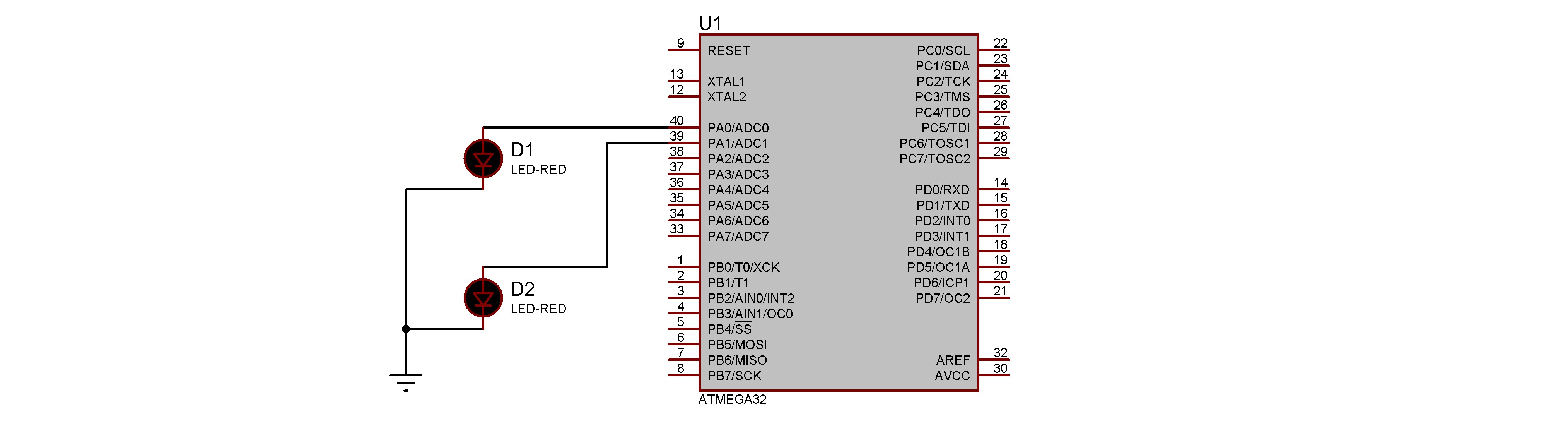
pin 10 (VCC)of the ATmega32 to theVCCof the adapter and thepin 11 (GND)of the ATmega32 to theGNDof the adapter. - The positive
+ends of the laser to ATmega32'spin 40 (A0)andpin 39 (A1). And the negative-ends to the ground of the power system.
- It is recommended to use an adapter to power the ATmega32 as the security system should be turned on all the time. So connect the

Every unit of the alarm system has two LDR sensors, which means one unit can secure two edges of the boundary. So a total of 2 units are required to secure a boundary of rectangular shape. The same is the case for the laser unit. See the image below for a better understanding.

- The GSM needs a current supply of 2A continuously. A battery is not enough to power the GSM. So, we had to use a power adapter or a power bank that can supply 2A continuously.
- The LDR sensor is too small. It is difficult to exactly point the laser to the LDR sensor from a long distance. So we have used a glass that can convege light (like the one in a torch light) to the LDR sensor.
- It is not possible to detect the exact timing of the laser's blink by the Arduino. Because there is a delay caused by the LDR and also in executing the code. We have seen that there is an error of 10-100ms. So, we had to use an error factor of 100ms while making a decision whether there is a breach or not.