The goals / steps of this project are the following:
- Compute the camera calibration matrix and distortion coefficients given a set of chessboard images.
- Apply a distortion correction to raw images.
- Use color transforms, gradients, etc., to create a thresholded binary image.
- Apply a perspective transform to rectify binary image ("birds-eye view").
- Detect lane pixels and fit to find the lane boundary.
- Determine the curvature of the lane and vehicle position with respect to center.
- Warp the detected lane boundaries back onto the original image.
- Output visual display of the lane boundaries and numerical estimation of lane curvature and vehicle position.
Rubric Points
Here I will consider the rubric points individually and describe how I addressed each point in my implementation.
1. Provide a Writeup / README that includes all the rubric points and how you addressed each one. You can submit your writeup as markdown or pdf. Here is a template writeup for this project you can use as a guide and a starting point.
You're reading it!
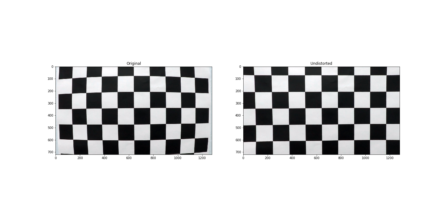
1. Briefly state how you computed the camera matrix and distortion coefficients. Provide an example of a distortion corrected calibration image.
The code for this step is contained in the section Camera Calibration of the IPython notebook located in the file P2.ipynb.
I begin by retrieving all the images provided for the calibration on the folder camera_cal using the glob library.
Then I get the real world points of a chessboard, generated by the numpy.mgrid function, providing the 9x6 size of the board.
To get the location of the corners in the images, I iterated every single file and use the function cv2.findChessboardCorners.
After we have retrieved all the real world and image coordinates of the chessboard corners, I provided them to the function cv2.calibrateCamera which calculated the camera matrix mtx and the vector of distorsion coefficients dist.
Using mtx and dist we can already start transforming images into their undistorted versions by using the code in cells 4 and 5 and obtaining the following result:
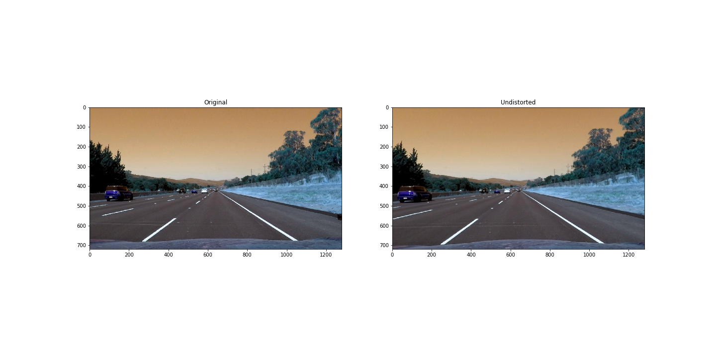
To demonstrate this step, I use the code provided in cells 4 and 5. And the process is to run the calibrate_camera function to get the camera matrix and distorsion coeficients and then providing them to the function cv2.undistort to obtain the undistorted image. A result of the sample can be seen below:
The difference is not huge after undistorting the images but it can be noticed by checking the front of the car at the bottom and the altered shape of the trees on both sides of the road.
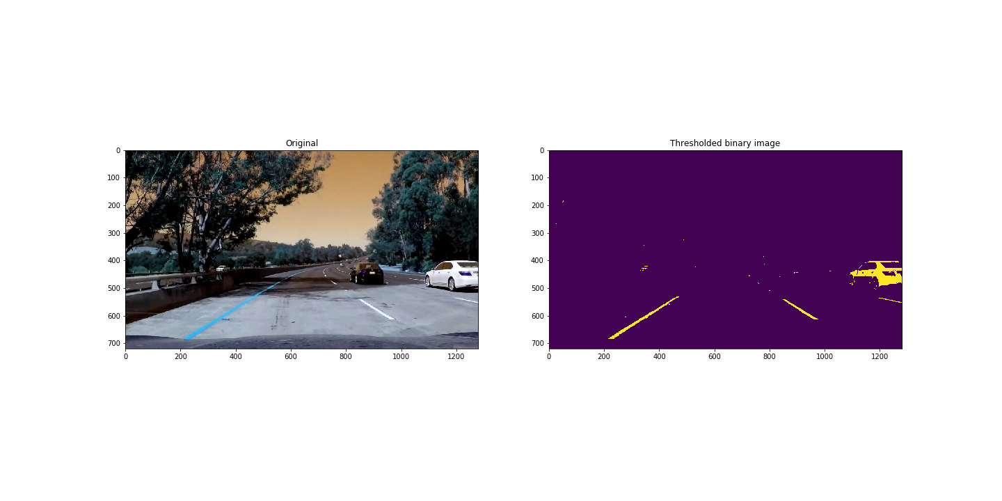
2. Describe how (and identify where in your code) you used color transforms, gradients or other methods to create a thresholded binary image. Provide an example of a binary image result.
I used a combination of color thresholds to generate a binary image. This is all done in the function create_binary_image in the PD.ipynb. The best results I've got are using the R channel from the RGB color space and the V channel from the HSV color space.
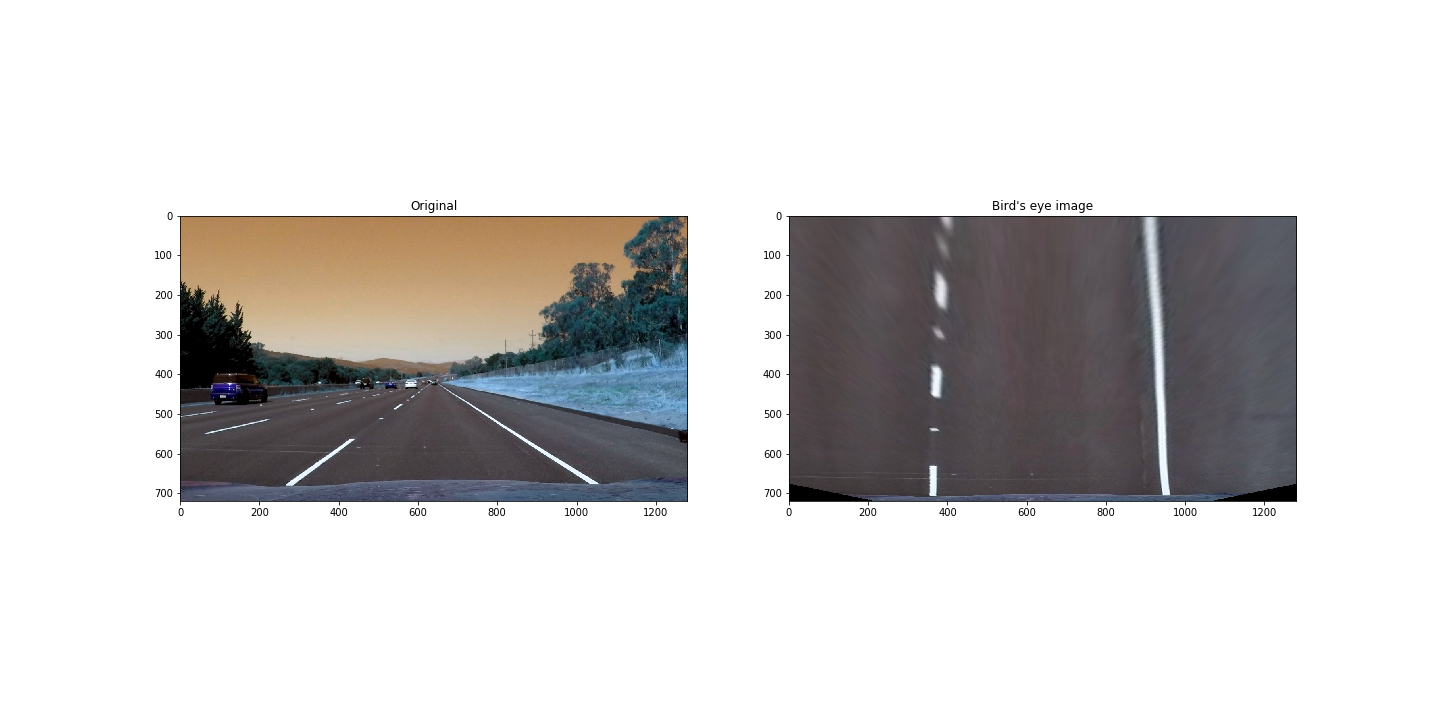
3. Describe how (and identify where in your code) you performed a perspective transform and provide an example of a transformed image.
The code for my perspective transform is divided in two functions. First function get_src_dst_points exists to conveniently provide the source and destination points for the perspective transform. First I initialize some strategic positions, like the bottom width, middle with, height percentage and so on, and then use them to generate the source and destination points drawing the interest rectangles.
In the second function transform_perspective, I combine the usage of cv2.getPerspectiveTransform and cv2.warpPerspective to get the warped image as shown below:
I can confirm that this method is working since the lines seem to be near parallel in a variety of test images.
4. Describe how (and identify where in your code) you identified lane-line pixels and fit their positions with a polynomial?
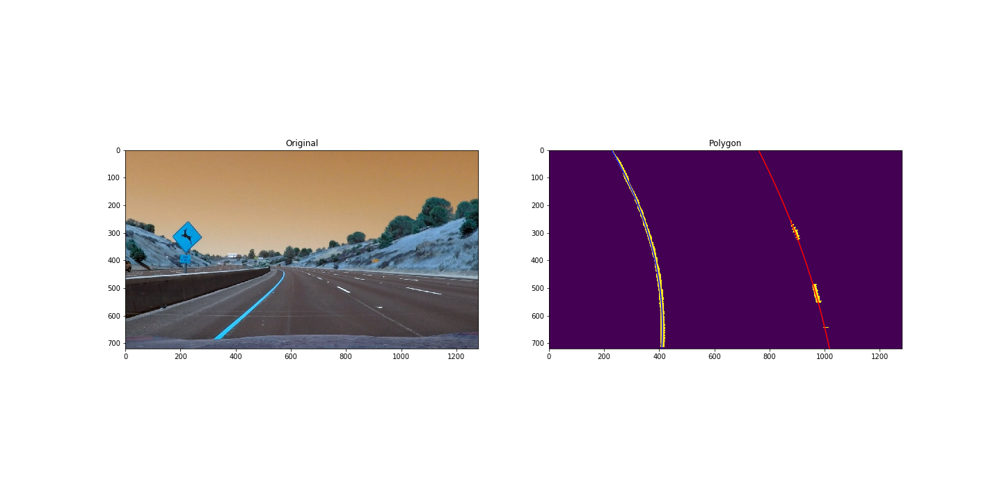
Once I get the perspective transformed binary image containing basically only the lines, I pass the image to my function find_lane_pixels. Here I generate the histogram of the image, to identify the x coordinate of the base of both the left and the right lines. After that I use the sliding window method to detect the line even when it's curved, all the way from the bottom of the image to the top. The output of this function will be four arrays: X cordinates of the left line, Y coordinates of the left line, X coordinates of the right line and Y coordinates of the right line.
The output mentioned above, will be used by the function fit_polynomial, and at the same time numpy.polyfit to generate one order 2 polynomial per line. A sample output that I've got is:
5. Describe how (and identify where in your code) you calculated the radius of curvature of the lane and the position of the vehicle with respect to center.
The radius of the curvature is also calculated in the function fit_polynomial, at the end of it, by applying the Radius of Curvature formula provided in the lessons.
For the position with respect to center, I calculated the X coordinates of each of the lines using the polynomial. Then I calculated the middle point between them and computed the difference with the middle point of the image (since it's assumed that the camera is in the center of the car). This will give us the distance in meters respect to center and it will be positive if the car is closer to the right line and negative if it's closer to the left line.
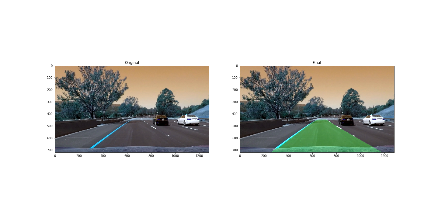
6. Provide an example image of your result plotted back down onto the road such that the lane area is identified clearly.
In section 6 of the notebook is the test pipeline to display the lane area identified correctly. Here is a sample image:
1. Provide a link to your final video output. Your pipeline should perform reasonably well on the entire project video (wobbly lines are ok but no catastrophic failures that would cause the car to drive off the road!).
Here's a link to my video result
1. Briefly discuss any problems / issues you faced in your implementation of this project. Where will your pipeline likely fail? What could you do to make it more robust?
There are plenty of problems on my pipeline, the video challenges are not well processed since different gradient and color threshold methods have to be applied. I could also improve the algorithm to use previous information on the lanes, as well as not needing to apply the window detection in every single frame, but just giving an estimate on where the lanes are.
