Working with micro-controllers, sensors and actuator
In the IoT system, It is essential to understand the environment and make changes to the environment. In this chapter, we will learn how to work with sensors and actuators.
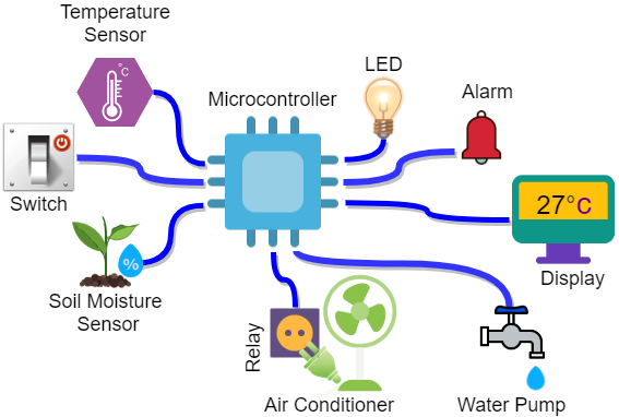
A greenhouse manager requests us to design a system that maintains the greenhouse temperature and humidity within the specified range. Besides, The system must automatically fill in water into the greenhouse whenever it is needed. This system should display the ambient temperature and humidity on the screen and turn on the air conditioner when needed.
Above figure shows a deeper look at the described project, we can understand the project is composed of:
- One sensor to get environment's temperature. i.e., BMP 280 sensor.
- BMP 280 is a sensor that can get the temperature, humidity and pressure of the environment with a good precision
- One sensor to get the environment's humidity. i.e., again BMP 280 sensor.
- One LCD to display necessary information. i.e., a 1-inch OLED display for the prototype (SSD1306).
- One Air conditioner. i.e., a DC motor for the prototype.
- One actuator to turn on or off the Air conditioner.
- One push button to disable or enable the system.
- One Buzzer
- One LED to show the running status.
- One Micro Controller. i.e., Arduino or Raspberry Pi.
- Wires, Resistances, Breadboard (for the prototype), etc.
In this lab we learn:
- Micro-Contoller
- Digital Signal and how to Read/Write in a Micro Controller
- Analog Signal and how to Read/Write in a Micro Controller
- PWM
- LED
- Arduino
- Arduino IDE
- Extra: Relay
- Extra: Fritzing
In this step, we work on the simplest part of the project.
A LED has two pins. Cathode (+) and Anode (-). To turn on a LED, we need to put it into an Electronic circuit.

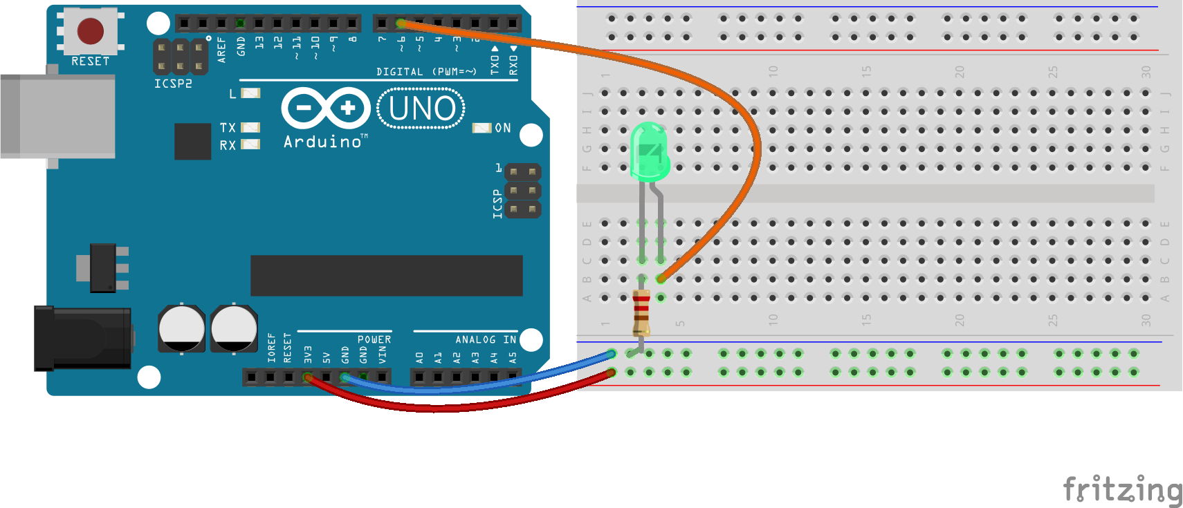
A breadboard is a construction base for prototyping of electronics. Because the solderless breadboard does not require soldering, it is reusable. This makes it easy to use for creating temporary prototypes and experimenting with circuit design.
In The above figure, you can see a breadboard design:
- [A, D]: bus strips. Each row is connected horizontally—usually the blue one for ground and the red one for a supply voltage.
- [B, C]: Terminal strips. All five pins in each column are connected together.
In this step, we connect LED to the Micro-Controller.
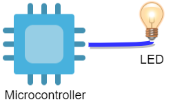 Before continuing, we need to know more about the element used in this section.
A microcontroller is a small computer on a single integrated circuit (IC) chip. A microcontroller contains one or more CPUs (processor cores) along with memory and programmable input/output peripherals.
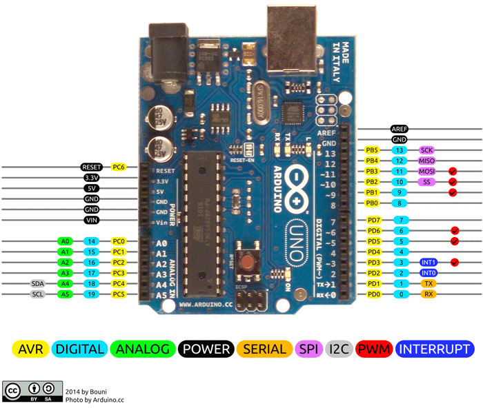
In this lab, We use an Arduino UNO development board.
- Operating Voltage: 5 Volts
- Input Voltage: 7 to 20 Volts
- Digital I/O Pins: 14 (6 provide PWM output)
- Analog Input Pins: 6
- DC Current per I/O Pin: 20 mA
- DC Current for 3.3V Pin: 50 mA
- Clock Speed: 16 MHz
- Micro controller: ATmega328P
- USB connection
Now, It is necessary to model the work.
Before continuing:
| Ex.1 | Test your LED by connecting the orange wire to the red bus (VCC). Is it work? Document it in your GitHub repository using this format. |
|---|
In this LAB, we will use Arduino IDE. However, you can use any software as you want. Download Arduino IDE How to install Arduino Simple Program: LED Blink.ino If you need help on arduino language. Arduino Language Reference
Each Arduino program, contains two parts. Setup and loop
The
setup()function is called when a program starts. Use it to initialize variables, pin modes, start using libraries, etc. Thesetup()function will only run once, after each powerup or reset of the Arduino board.
After creating a
setup()function, which initializes and sets the initial values, theloop()function does precisely what its name suggests, and loops consecutively, allowing your program to change and respond. Use it to actively control the Arduino board.
A digital value is Zero or One. i.e., An LED is on or off or a button is pressed or not. To write a digital value we can use
digitalWrite (port_number, LOW or HIGH). Be sure that you have setup theport_numberasOUTPUTby usingpinMode(port_number, OUTPUT);in thesetupfunction.
| Ex.2 | Turn on and off an LED in port 4. Is it work? Please don't forget to document it with this format. |
|---|
Hint: You have to use :
pinMode(buttonPin, INPUT);in setup and to read the digital signal you can usebuttonState = digitalRead(buttonPin);ThebuttonStatevalue is eitherHIGHorLOWi.e., You can useif (buttonState == HIGH){....}else{....}
| Ex.3 | Is it work? Please don't forget to document it with this format. |
|---|
Please do the lesson 4 in the same file.
Hint: You have to use : to read the analog signal you can use
value=analogRead(A0)Thevalueis something between 0 and 1024. If the input voltage is 5V thevaluewill be 1024, if it is 2.5V itvaluewill be 512 and if it is 0V thevaluewill be 0.
| Ex.4 | Is it work? Please don't forget to document it with this format. |
|---|
Now it is time to do the lesson 5 in the same file.
you can use
analogWrite(pin, value). Thevalueis the duty cycle: between 0 (always off) and 255 (always on).
| Ex.5 | Is it work? Please don't forget to document it with this format. |
|---|
Please do the lesson 9 in the same file.
to generates a 400Hz tone in output pin 8 with 2000ms of duration you can use
tone(8, 400, 2000);
| Ex.6 | Is it work? Please don't forget to document it with this format. |
|---|
Please do the lesson 10 in the same file.
A RGB LED can produce any color as you want. Like normal colors we have 3 primitive color: Red,Green and Blue. by controlling the amount of each we can have different colors.
Please write a function setColor(int red,int green, int blue) and do analogWrite(color_pin,color_value) for each color (i.e., for red one analogWrite(red_pin,red)) and then call setColor(r,g,b) in your loop.
| Ex.7 | prepare a program to have different colors (at least 5) with a delay of 1000 ms . Is it work? Please don't forget to document it with this format. |
|---|
