This project provides an easy-to use programming API to emulate a Nintendo Switch controller using an Arduino UNO R3.
The API allows sending button presses/stick movements on the emulated controller, to read the state of a physical button connected between the Arduino’s pins 12 and ground, and to control the Arduino’s on-board LED as well as an external buzzer.
A sample program is provided to automate some tasks in Pokémon Sword/Shield. Details about this can be found in this file.
The Arduino UNO R3 board has a ATmega328P microcontroller. User code programmed using the Arduino IDE runs on this microcontroller, which controls most I/O pins on the board.
There is, however, another microcontroller on the board (the small square chip between the USB port and the RX/TX LEDs). This is a ATmega16U2, and it controls the USB interface.
By default, the 16U2 simulates a USB-to-serial interface. Serial port access
from the 328P (using for instance the Arduino Serial library) are routed
through the 16U2 before getting to the attached computer.
Using an external ISCP programmer, it is possible to reprogram the 16U2 in order to make it simulate a USB Nintendo Switch controller and send inputs directly. This is the approach used in [1]; with this configuration, the 328P is not used at all and can even be removed from the board. The main drawback, however, is that the 16U2 has limited RAM and Flash space, and cannot access most I/O ports on the Arduino board.
A better approach is to use both microcontrollers:
- The ATmega328P reads inputs from the user, display current status, decides which inputs to simulates, and send the calculated inputs to the ATmega16U2.
- The ATmega16U2 receives commands from the ATmega328P and forwards them to the USB interface as data.
This also allows asynchronous handling: the 16U2 can continue to process USB requests from the attached computer/Switch while the 328P is blocked in a delay loop or waiting for user input.
The 328P also does not need to include a library to deal with USB requests, since it only needs to be able to send commands to the 16U2; this frees up space for more application code.
An example of this approach (for a generic USB controller) can be found on [2] (Internet Archive link).
See the DESIGN file for more implementation details.
- An Arduino UNO R3
- A push button plugged between pins 12 and GND on the top connector. Most push buttons should be able to be plugged directly on the Arduino board, without extra circuitry.
- An external ICSP programmer, like the AVRISP mkII. It may be possible to reprogram the Arduino using DFU mode (according to [2]) but this has not be tested. (Note: DFU programming may also stop working once this program is flashed onto the Arduino, so you should not attempt it if you do not have access to an external programmer)
- A buzzer can be optionally attached between pins 2 and GND of the Arduino board, in order for the automation process to notify the user when something needs their attention.
An AVR toolchain providing avr-gcc, avr-objcopy and avrdude in the
PATH. On macOS,
CrossPack AVR can be
used.
LUFA [3] is used for the USB interface handling; it is included in this repository as a submodule and will be automatically retrieved if needed.
Running make will produce the following files:
usb-iface.hexis the program for the ATmega16U2 managing the USB interface.swsh.hexis the Pokémon Sword/Shield automation program, running on the ATmega328P. You can create your own automation program and edit theMakefileto build it.
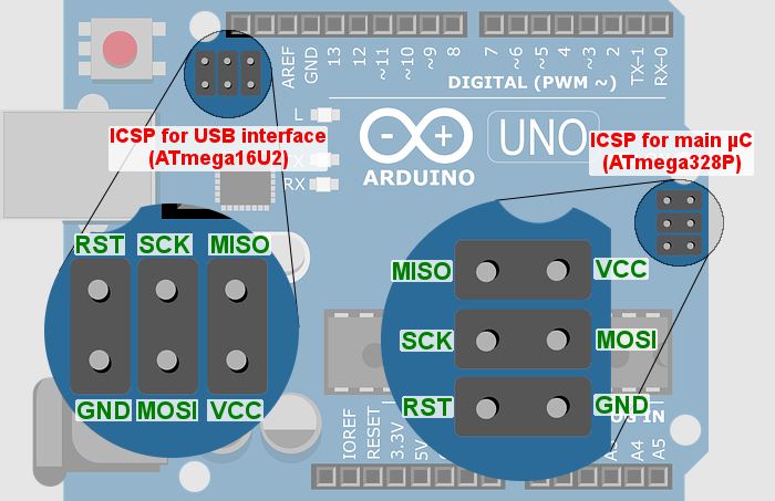
The Arduino UNO R3 has two headers for programming the USB interface controller and the main microcontroller, respectively. Their pinouts are indicated in the following picture:
Start by connecting the programmer to the ISCP header for the USB interface.
(Some programmers’ connectors have a notch on the MISO/SCK/RST side that will
bump into the top I/O header, making it a tight fit). Flash the usb-iface.hex
file, either manually or by running make flash-usb-iface.
Unplug the programmer and connect it to the main microcontroller’s ISCP header.
Flash the swsh.hex file, either manually or by running make flash-swsh.
To restore the original Arduino USB interface and bootloader, follow these steps:
-
Connect the programmer to the ISCP header for the USB interface and flash the
UNO-dfu_and_usbserial_combined.hexfile that can be found on [4]. This can be done automatically by runningmake restore-usb-iface. -
Connect the programm to the ISCP header for the main microcontroller, and start the Arduino IDE. Make sure that the correct programmer is selected in the
Tools>Programmerand selectTools>Burn bootloader.
The Arduino should then be programmable using its regular USB interface.
