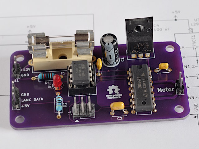
LANC zoom controller
This project is a circuit board intended to control a DC motor from a “zoom controller” wired remote conforming to the Sony's LANC protocol.
Motivation
Many people use DSLRs to record high-quality video despite their inferior ergonomics relative to conventional camcorders. When mounted on a tripod, many camcorders can be zoomed in and out using a wired remote control, commonly known as a “zoom controller”. In contrast, most DSLRs have non-motorized zooms, and reaching for the zoom ring is inconvenient when the camera is tripod-mounted.
The purpose of this project is to be able to control the zoom ring of a DSLR using the same kind of wired remote one would use with a camcorder. Specifically, this circuit board interfaces with remotes supporting the widely used Sony's LANC protocol, and is capable of driving a low-power DC motor from a 12 V power supply. It is up to the user to rig a DC motor to the zoom ring of their lens.
Principle of operation
The main parts of the circuit are an H bridge for driving the DC motor and an ATtiny microcontroller for driving the H bridge and handling the communication with the wired remote.
The remote sends commands such as “zoom in at speed #2” or “zoom out at speed #5”. In response to these commands, the microcontroller sets the direction of rotation of the motor, and sends a PWM signal to the “enable” input of the H bridge. The duty cycle of the PWM signal depends on the speed selected by the remote. This duty cycle in turn controls the average power received by the DC motor. There is no feedback from the motor, thus no precise control on its actual rotational speed.
Building the circuit
Build the PCB according to the layout file ctrl-zoom.kicad_pcb, which is in the format of the free KiCad design software. Many professional PCB shops can do it for you if you provide the proper design files. Some accept the KiCad format directly, and need only that file. Others require the design to be provided as a set of “Gerber” and drill files. In this case, install KiCad, open ctrl-zoom.kicad_pcb with KiCad, and let it generate the required files (menu: File → Plot...).
Get the parts listed below and solder them to the board. All are through-hole components. Refer to the schematic and the labels on the PCB's silkscreen for the correct placement and orientations.
| designator | quantity | item |
|---|---|---|
| U1 | 1 | L7805 voltage regulator, 5 V, TO-220 package |
| U2 | 1 | ATtiny25-20PU, DIP-8 package [1] |
| U3 | 1 | L293D H-bridge, DIP-16 package |
| C1 | 1 | 100 µF radial electrolytic capacitor, ⌀ 6.3 mm |
| C2 | 1 | 1 µF ceramic capacitor, pin spacing: 5 mm |
| C3, C4 | 2 | 100 nF ceramic capacitor, pin spacing: 5 mm |
| J1, J3 | 2 | 1×2 male pin header, pitch: 2.54 mm |
| J2 | 1 | 1×3 male pin header, pitch: 2.54 mm |
| J4 | 1 | 2×3 male pin header, pitch: 2.54 mm |
| F1 | 1 | 1 A, 5×20 mm fuse + Stelvio-Kontek PTF78 holder |
| D1 | 1 | 3 mm LED |
| R1 | 1 | 10 kΩ resistor |
| R2 | 1 | 470 Ω resistor |
[1] Any ATtiny of the same family can be used (25, 25V, 45, 45V, 85, or 85V). It is recommended to use a DIP-8 socket, rather than soldering the ATtiny directly to the board.
Building and uploading the firmware
You need GNU make, avr-gcc, avr-libc, avrdude and an ISP programmer. An Arduino can be used as an ISP programmer. On Ubuntu Linux, you can install the required software by typing:
sudo apt install make gcc-avr avr-libc avrdudeMove to the firmware directory, edit the MCU and PROGRAMMER
variables in the Makefile, then type:
makeFor uploading the firmware, connect the programmer to your computer and the ISP header (J4) on the board, paying attention to the orientation (pin 1 is bottom left, identified by the white triangle). Then type:
make uploadUsage
You will first have to rig a geared DC motor to the zoom ring of your lens. Then connect the LANC wired remote to the connector on the left side of the PCB labeled “J2” and the motor to the right-side connector (J3). The power supply should be connected last, to J1. Actuate the remote and check that the lens zooms in the desired direction. If this is not the case, reverse the connection of the motor on J3.
If you are not pleased with the way the motor power varies as a function of the remote's knob position, you can customize this dependency by modifying the firmware. Near the top of ctrl-zoom.c, locate the lines:
/* Available motor speeds. */
static __flash const uint8_t speeds[8] = {
    2, 4, 8, 16, 32, 64, 128, 255
};
These are the PWM levels corresponding to the 8 speeds that the remote can request. Change these to your liking, rebuild the firmware and upload it again (with the supply, the remote and the motor disconnected).
License
This project is open-source hardware. All of its files, including firmware source code, design files and documentation, are provided under the terms of the MIT licence. See the included LICENSE file.
If you use any of this, I would appreciate if you drop me a note. If you improve on it, you are encouraged to contribute the changes back to the open-hardware community. These are not, however, legal requirements: only the terms of the license are legally binding.
