C4C1 Simulated CPU Project
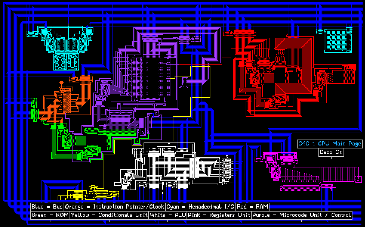
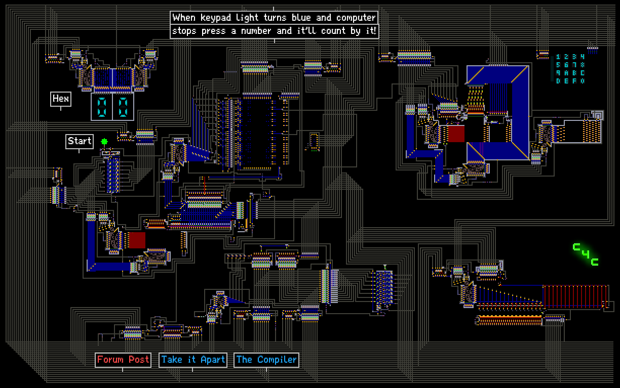
The C4C1 Simulated CPU is an 8-bit general purpose computer design project that I worked on from 2016 to 2017. The CPU runs inside of a physics engine known as PowderToy, which has a major community using it to make simulated digital devices and computers. It was a rewarding journey that taught me low-level computer concepts ranging from assembly language to computer logic. Below is the slightly-modified overview I wrote about the computer and how it works.
 C4C1 Disassembled Simulator Page
Intro
Hey guys. I have finally finished a project that I have been working on for months
now, my very own PowderToy computer! The C4C 1 8-bit Computer is now fully functional,
complete with detailed documentation and a block diagram of the internals. I am very proud
to join the community of people who develop complex electronics and computers on TPT.
You guys are truly amazing, and the feats you accomplish together as a
community are incredible (60 hz computer, GPU, video game inside a video game, etc.)
I hope to now play my part in this incredible community.
Features
- An 8-bit Semi-Von Neumann architecture (data/addresses are 8 bits wide at maximum)
- A 256 byte ROM and 256 byte RAM
- 16 general purpose registers (AX - PX)
- Hexadecimal keyboard and display
- A 7 function ALU
- 16 assembly instructions
- A microcoded CPU
Detailed Specification
Before we get into the computer, here is a complete specification for further reading:
And here is the block diagram:
I prepared some concise notes on the instruction set architecture, found here:
Simulation Files and Images
You can access the webpages for my simulator saves at the top. I also saved the main simulation files here:
This repo includes a variety of images of the build process, final computer, and more here:
Programming Instructions
Finally, we get to the programming reference. You need technical knowledge for this section. It is taken from the reference. In the ROM, data is stored in filt (a light filter element). Filt uses a hex number which corresponds to a 30-bit wavelength in the CTYPE, adapted from storing colors to encoding instructions/data:
Instruction Bitfield:
[11111][xxxx][xxxxxxxx][xxxxxxxx][00000]where INST = which instruction[IDENT][INST][OPERANDA][OPERANDB][EMPTY]
Data Bitfield:
[0000000000000000000000][xxxxxxxx][_______ UNUSED _______][_ DATA _]
Register Bitfield (for use in operands):
[0000][xxxx]where addr = address of register from 0 - 15 (AX - PX)[NONE][ADDR]
And an assembly instruction corresponding to instructions or data:
- Instruction:
[MNEMONIC] [OPERANDA], [OPERANDB] - Data:
DB [8BIT-BYTE]
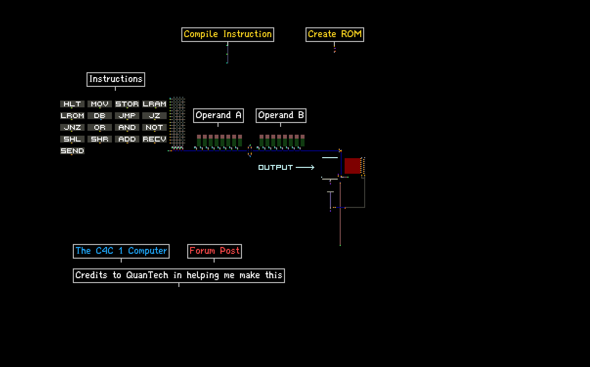
Update: Use the compiler linked at top, type assembly instruction, followed by binary operands into compiler, then press compile instruction. When done with entire program, press create image and copy that ROM.
To program the C4C 1 CPU in PowderToy, there are several steps you need to take:
- Write out the instruction in assembly mnemonics, e.g. MOV AX, BX
- Find the binary address corresponding to the instruction, e.g. 0001 for MOV
- Encode the operands in binary, e.g. OPERANDA[AX] becomes 00000000 and OPERANDB[BX] becomes 00000001
- Put the instruction together in binary, with the identifier at the front, followed by the binary instruction address, followed by the operands, and lastly the sequence 00000 e.g. 11111 + 0001 + 00000000 + 00000001 + 00000 => 111110001000000000000000100000
- Convert the instruction from binary to hex, e.g. 111110001000000000000000100000 => 0x3E200020
- Set the PROP tool to edit CTYPE and paste the hex instruction with the "0x" at the front, click OK and click on the filt memory cell you want to write to. The cells go from left to right, then top to bottom. (Address 0 - 15 first row, 16 - 31 second row, and so on until address 255)
Putting data into the ROM is similar. Simply convert the 8 bit byte to hex, put the 0x in front of it, paste it into the PROP tool with it set to CTYPE, and click on the filt memory cell you want to write to.
Instruction Reference
HLT [NONE]
- Address: 0000
- Stops and resets the CPU
MOV a, b [REGISTER],[REGISTER]
- Address: 0001
- Copies the value of register b to register a
STORE a, b [RAMADDR], [REGISTER]
- Address: 0010
- Stores contents of register b in RAM memory location a
LOADRAM a, b [REGISTER], [RAMADDR]
- Address: 0011
- Loads contents of RAM memory location b into register a
LOADROM a, b, [REGISTER], [ROMADDR]
- Address: 0100
- Loads contents of ROM memory location b into register a
DB a [CONSTANT]
- Address: None
- This is a special instruction - the value of a is simply stored in the ROM, using the data bitfield. DB stands for data byte - the instruction stores one 8 bit byte. This data can be retreived using LOADROM, where the value for the ROM address would be the address of this byte
JMP a [ROMADDR]
- Address: 0101
- Changes value of instruction pointer to the value of a - this is an unconditional jump
JZ a, b [ROMADDR], [REGISTER]
- Address: 0110
- Changes the value of the instruction pointer to the value of a only if the value of register b is zero - this is a conditional jump
JNZ a, b [ROMADDR], [REGISTER]
- Address: 0111
- Changes the value of the instruction pointer to the value of a only if the value of register b is not zero - this is a conditional jump
OR a, b [REGISTER], [REGISTER]
- Address: 1000
- Performs logical or on values of registers a and b, stores result in register a
AND a, b [REGISTER], [REGISTER]
- Address: 1001
- Performs logical and on values of registers a and b, stores result in register a
NOT a [REGISTER]
- Address: 1010
- Performs logical not on value stored in register a and stores the value in register a
SHL a [REGISTER]
- Address: 1011
- Performs an overflow, destructive left shift on register a
SHR a [REGISTER]
- Address: 1100
- Performs an overflow, destructive right shift on register a
ADD a, b [REGISTER], [REGISTER]
- Address: 1101
- Adds the values of registers a and b together, stores result in register a
RECV a [REGISTER]
- Address: 1110
- Receive a value into register a from the I/O port
SEND a [REGISTER]
- Address: 1111
- Send a value from register a to the I/O port
Example: Fibonnaci Sequence Program
DB 1		;Store the value 1 in memory cell 0

SEND AX 	;Since all registers are 0 at CPU start, I can output 0

LOADROM AX, 0	;Load memory cell 0 (a value of 1) into AX

SEND AX 	;Perform fibbonaci

MOV CX, AX

ADD AX, BX

MOV BX, CX

SEND AX 	;Output fibonnaci

JZ 11, AX 	;Jump to terminate if AX overflows

JMP 4 		;Jump back to fibonnaci

DB 0xEE 	;Store 0xEE

LOADROM AX, 10 	;Retrieve 0xEE

SEND AX 	;Print "EE" on display, signifies overflow

DB 0 		;One byte of padding

HLT 		;Halt
For more example programs, go to the sample_programs directory.
Virtual Machine Emulator for C4C 1
I made an emulator in C for the C4C 1 machine. The code is here:
It runs a hardcoded program, simulating CPU state and memory.
Conclusion
I am very happy to finally be done with this. If you have any bugs, post them in this thread or
DM them to me using the PowderToy message system. Also post or send me any questions.

