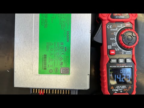
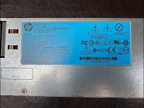
HP HSTNS-PL11/PL30/PL42 1200Watt Hot Plug Power Supply Hack for Vehicle Flashing and Programming. The HPE PSU is a powerful and versatile power supply unit that can be modified or hacked to suit a wide range of needs,With some basic electronics knowledge and proper safety precautions, it's possible to make this PSU even more useful and versatile for your specific applications. Modified HPE PSUs are suitable for RC battery charging, radio power supply, and vehicle flashing/powering applications.
To activate the PSU, add a small resistance resistor between Pin 33 and 36 or simply short them together.
33: ENABLE#
36: PRESENT


Pin1 - PGEC
Pin2 - PGED
Pin3 -
Pin4 - GND
Pin5 - Vcc(3.3V)

- Type III Compensator Using Op-Amp
Type III compensators are a type of compensation network used in control systems to improve stability and performance.
Locate the Type III compensator in the HP PL30 power supply by examining the PCB for the Op-Amp TSV994

To increase the output voltage, one can either increase the reference voltage or decrease the resistance value of R4.


Assuming the default Output is 12.32V.
There are two approaches to prevent the OVP (Over Voltage Protection) from being triggered, one is to add a resistor in parallel with the 01B resistor, the other is to modify the firmware of the MCU(dsPIC33FJ64GS606).
R1 is used to adjust the output voltage of the power supply, while R2 is used to adjust the threshold of the Over Voltage Protection (OVP).
The modification mentioned above is not meant to increase the OVP threshold, but rather to trick the dsPIC33FJ64GS606 MCU into thinking that the output voltage has not been adjusted.
--- PL30/10/DSPIC33FJ64GS606.hex	2023-03-12 14:10:17.000000000 -0700
+++ PL30/10/Patch/DSPIC33FJ64GS606.hex	2023-04-11 10:05:24.000000000 -0700
@@ -1802,7 +1802,7 @@
 :10708000D06E88000603A90091C0A9004400F90051
 :107090004F047800CF0278004F027800CF017800CB
 :1070A0004F017800CF0078004F00780000400600C4
-:1070B000811F7800851F7800211A80000150880008
+:1070B000811F7800851F7800E134070001508800A7
 :1070C000155280008582400011508000818252005C
 :1070D00015528800C2AADE0015508800311A8000BF
 :1070E00051528800D5E9AE00060037004501200066
@@ -4747,7 +4747,7 @@
 :10288000D06E88000603A90091C0A9004400F90099
 :102890004F047800CF0278004F027800CF01780013
 :1028A0004F017800CF0078004F007800004006000C
-:1028B000811F7800851F7800211A80000150880050
+:1028B000811F7800851F7800E1060700015088001D
 :1028C00015528000858240001150800081825200A4
 :1028D00015528800C2AADE0015508800311A800007
 :1028E00051528800D5E9AE000600370045012000AE
@@ -5188,8 +5188,8 @@
 :104410008080A900FFFF37000000FE00FFFFFF00C3
 :10442000FFFFFF00FFFFFF00FFFFFF00FFFFFF0098
 :10443000FFFFFF00FFFFFF00FFFFFF00FFFFFF0088
-:10444000FFFFFF00FFFFFF00FFFFFF00FFFFFF0078
-:10445000FFFFFF00FFFFFF00FFFFFF00FFFFFF0068
+:104440000000F800211A8000C0072000808F500073
+:1044500001003600808050000000F90000000600D6
 :10446000FFFFFF00FFFFFF00FFFFFF00FFFFFF0058
 :10447000FFFFFF00FFFFFF00FFFFFF00FFFFFF0048
 :10448000FFFFFF00FFFFFF00FFFFFF00FFFFFF0038
The code snippet above is PL30 Output set to 14.28V
PL30 Rev10 Firmware With Output 15.2V
PL42 Rev01 Firmware With Output 14.28V

By tweaking the potentiometer in the diagram, you can cap the maximum output current of the circuit. And if the range falls short of what you need, you can also swap out the 4.42k(labeled '63B') resistor to get the desired result. Alternatively, you can patch the firmware to limit the maximum output current.
The current flowing through the CT(Current Transformer) is transformed into a voltage signal and subsequently amplified using an amplifier. The amplified voltage is directly proportional to the output current


There are two approaches to prevent the OVP (Over Voltage Protection) from being triggered, one is to connect a resistor in parallel, the other is to modify the firmware of the MCU(PIC16F883).
R3 is used to adjust the output voltage of the power supply, while R4 is used to adjust the threshold of the Over Voltage Protection (OVP).
The modification above is not to increase the OVP threshold, but to make the MCU believe that the output voltage has not been adjusted.
Vdd is the supply voltage of the PIC16F883. By default configuration, The OVP voltage is dependent on the MCU supply voltage, which is approximately 13.86 volts in this case.
PL11 Rev12 Firmware With OVP Disabled

The output voltage of the CT amplified is divided down to 5V and fed into the MCU(PIC16F883). Adding a resistor in parallel across the 8.2k(labeled '8201') resistor can reduce the maximum output current.
A more effective approach would be to measure the voltage at OC_DET along with the actual output voltage of amplifier, and calculate the appropriate divider ratio.
Shorting the 8.2k resistor would cap the maximum output current at around 30A.
The current flowing through the CT(Current Transformer) is transformed into a voltage signal and subsequently amplified using an amplifier. The amplified voltage is directly proportional to the output current
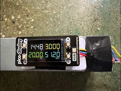
 The image above shows the Raspberry Pi Pico reading data from the HP HSTNS-PL30 power supply via I2C, measuring electrical parameters such as Amps, Volts, Watts, and Watt-hours, and displaying the results on the PIMORONI Pico Display Pack.
| PICO | PL30 |
|---|---|
| VSYS(39) | 3.3V |
| GND(38) | GND |
| GP4/SDA(6) | 31 |
| GP5/SCL(7) | 32 |
BOMs
- Raspberry Pi Pico
- Pico Display Pack
PICO Firmware 14.48V


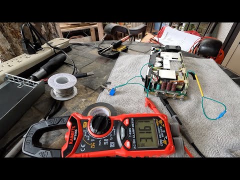
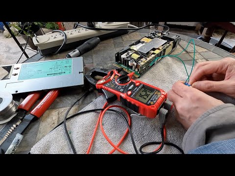
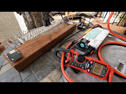
When conducting load testing with ignition ON and AC running, the fan operates at its maximum speed. The output voltage reads 14.28V with no load. However, when under load, there is a voltage drop caused by the impedance in the wires, which is expected. Technically speaking, I would recommend employing Nichrome 80 12 gauge AWG resistance wire for the construction of a dummy load.
PL11/PL30/PL42 Load With Fan on MAX,Audio,High Beam activated

HP HSTNS-PL11 Modification
HP HSTNS-PL30/PL42 Modification
HP HSTNS-PL11 OCP Modification
HP HSTNS-PL30 PICO Watt Meter
HP HSTNS-PL33 Modification

HP HSTNS-PL28 Modification
HP HSTNS-PD19 Modification
HP HSTNS-PD52 Modification