The notes I took while taking my ham radio permit class. Each exam question answer will be identified by it's question number (ex.: 5.10.11)
- Basics of electricity & resistance
- Measuring electricity & current
- Capacitors, inductors and transformers
- Rules and operation
- From vacuum tubes to semiconductors
- Power supplies, amps and oscillators
- A world of telecommunications and emitters
- Receivers and digital transmissions
- Powerlines and antennas
- Antennas part 2 and interference
- Waves, an opening to the world and measuring equipment
IPR-4 is the Canadian reference for which bands are available for which license.
Ham radio logo is the following:

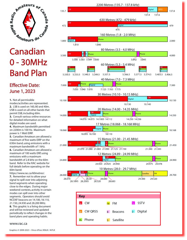
Canadian Band plan:
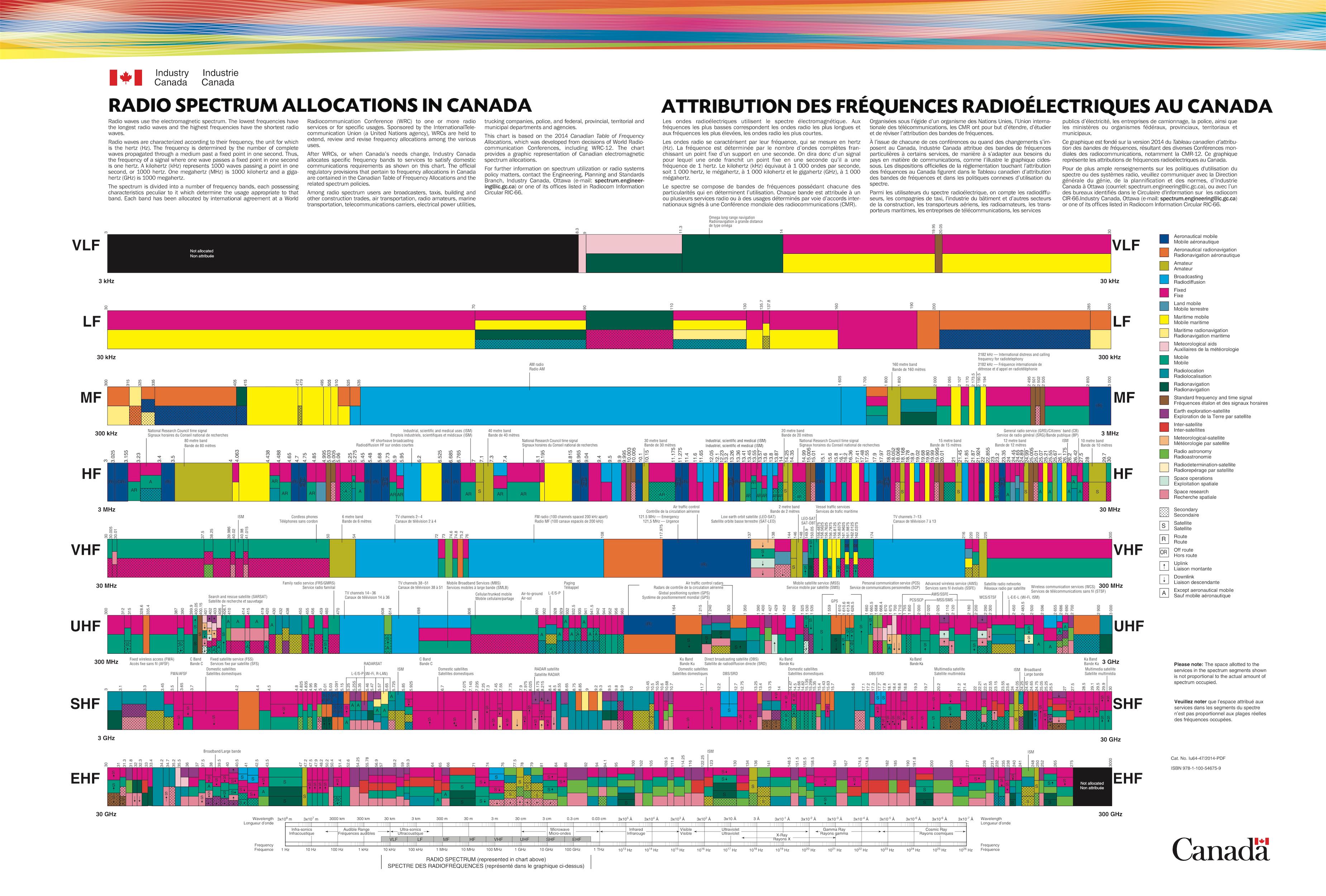
Canadian Radio Frequency Allocation table:
- 5.2.1: Gold, silver and copper are good conductors.
- 5.2.2: Materials such as glass, porcelain, rubber, plastic and wood are good insulators.
- 5.2.4: The most used condutor is copper.
- 5.2.5: Material that conduct electricity well are called conductors.
- 5.2.6: Material that conduct electricity poorly are called insulators.
- 5.2.8: The opposite of resistance is conductance.
- 5.11.5: The instance of a magnetic field in a free space is directly proportional to the intensity of the current flowing through the conductor.
- 5.11.7: In a conductor, the induced tension is perpendicular to the magnetic field andto the direction of the current.
- 5.11.9: All magnets have a north and south pole. North and south poles attract each other, while poles of the same type repel each other.
- 5.11.10: A permanent magnet is typically made of iron.
- 4.6.1: The fourth band represents the tolerance of the resistor.
- 4.6.2: The 3 first color bands on a resistor represent the value of the resistor represented in ohms.
- 4.6.3: The first band represents the first digit of the value of the resistor. The second band represents the second digit of the value of the resistor. The third band represents the number of zeros to add to the value of the resistor. The fourth band represents the tolerance of the resistor.
- 4.6.4: The actual resistance will typically be within 5%, 10% and sometimes 20% of the value of the resistor.
- 4.6.5: The resistance of a resistor is represented by a color code.
- 4.6.6: Resistance of great quality will typically only vary by 0.1%.
- 4.6.7: When using an LED, the real resistance doesn't matter much. 20% is typically fine.
- 4.6.8: When a carbon resistor is heated, it's resistance increases. The resistance changes based on it's heat coefficient.
- 4.6.9: Gold typically indicates a 5% tolerance. Silver typically indicates a 10% tolerance. No band typically indicates a 20% tolerance.
- 4.6.10: The third band will, for example, distinguish a 100ohm resistor from a 1000ohm resistor.
- 5.2.3: When a resistor gets hot, it means it's dissipating energy.
- 5.2.7: Resistance is measured in ohms. It's represented by the omega symbol.
- 5.2.10: The resistance of a conductor varies with it's heat.
- 5.2.11: The most used resistance is the carbon resistor.
- 5.5.3: When in parallel within a circuit, the total resistance is lower than the lowest resistance of the resistors in parallel.
- 5.5.5: Resistors in series are added together.
- 5.5.6: For example, 5 10ohm resistors in series will have a total resistance of 50ohms.
- 5.5.7: For example, 5 24ohm resistors in series will have a total resistance of 120ohms.
- 5.5.8: When multiple resistors are in parallel and have the same value,
the total resistance formula is
Rt = R / nwhereRis the resistance andnis the number of resistors. When they are not of the same value, the formula isRt = (r1 * r2)/(r1 + r2). - 5.5.9: For example, a total of 4 68ohms resistors in parallel will have a total resistance of 17ohms.
- 5.6.1: When we need to dissipate energy has heat, it's best to pick a larger resistor even if a smaller one has the same ohmic value.
- 5.6.10: There's also an advantage to replacing a 50ohm resistor with two 100ohm resistors in parallel. The power of the circuit will be higher despite the same ohmic value.
- 5.6.11: The power rating of a resistors is based on it's ability to dissipate heat.
Read chapter 3 and 4 of the electricity book.
Here is the unit conversion chart:

Here are the formulas for calculating power, tension and current:
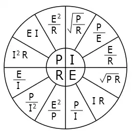
More specifically, here are the formulas where P is power, E is tension, R is resistance and I is current:
- I^2 * R = P
- E * I = P
- E^2 / R = P
- sqrt(P/R) = I
- P / E = I
- E / R = I
- squart(P * R) = E
- I * R = E
- P / I = E
- E^2/P = R
- P / I^2 = R
- E / I = R
- 5.1.1: A dial indicating 3,535MHz is equal to 3535 kHz.
- 5.1.2: If we measure a current of 3000 mA, it's equal to 3A.
- 5.1.3: If we measure a tension of 3500 mV, it's equal to 3.5V.
- 5.1.4: A condensator of 1000000 pF is equal to 1 uF.
- 5.1.5: A 500mW transmitter is equal to 0.5W.
- 5.1.6: a kOhm is equal to 1000 ohms.
- 5.1.7: A tension of 6,6 kVolts is equal to 6600 V.
- 5.1.8: A current of a quarter Amp can be written as 250 mA.
- 5.1.9: A tension of 2 volts is equal to 2000 mV.
- 5.1.10: a MHz is equal to 1000000 Hz.
- 5.1.11: An inductance of 10000 uH can be written as 10 mH.
- 5.2.9: Tension drop is the difference between the tension at the beginning and the end of the circuit
- 5.3.1: Power is the word used to express the speed at which energy is used
- 5.3.2: Out of a 40W, 80W and 100W lightbulb, the 100W lightbulb will be the
- 5.3.3: Watts are used to express the power of a circuit
- 5.3.4: When a circuit is opened, one that consumes the most
- 5.3.5: When a circuit requires too much current, it'll short circuit
- 5.3.6: Watts are used to express the power of a circuit
- 5.3.7: To know the power, we multiply the tension by the current
- 5.3.8: To know the power, we multiply the tension by the current
- 5.3.9: In a circuit, when a resistance becomes too hot it means the current has too much power
- 5.3.10: High resistance tend to have a large body and a large wire. These characteristics allow them to dissipate heat faster.
- 5.3.11: Of a 5W, 2.5W, a 10W and a 20W, the resistance that can dissipate the most heat is the 20W one
- 5.4.1: A current of 2 amps goes through a 50 ohms resistance, which voltage appears appears at the leads?
- 5.4.2: The current is equal to voltage divided by resistance
- 5.4.3: Resistance is equal to voltage divided by current
- 5.4.4: Voltage is equal to current multiplied by resistance.
- 5.4.5: If a 12V battery has a current of 0.25A in it's circuit, what is the resistance of the circuit?
- 5.4.6: Calculate the resistance required to obtain a drop of 100V with the current is 0.8mA
- 5.4.7: Which tension is required to force a current of 4.4A through a resistance of 50 ohms?
- 5.4.8: A lamp has a resistance of 30 ohms with a current of 6V, how many amps is circulating in the lamp?
- 5.4.9: Which tension is necessary to force a current of 200 mA though a lamp that has a resistance of 25 ohms?
- 5.4.10: Voltage is equal to current multiplied by resistance.
- 5.4.11: If a battery has 3V and is pushing a 300mA current, what is the resistance in the circuit?
- 5.5.1: The current given by a circuit is equal to the sum of the current circulating in all branches of the circuit.
- 5.5.2: The sum of the current circulating in each resistor is equal to the total current drained in the battery.
- 5.5.4: If two resistors have a value of 1000 ohms, the total current is 80mA.
- 5.5.10: If two resistance are placed in parallel and the resistance of resistor A has a current twice as high as resistor B, this means resistor A is twice as low as resistor B.
- 5.6.2: How many Watts will be used by a lamp of 12 volts and 0.2A?
- 5.6.3: What is the power of a transmitter that consumes 500mA under 12V?
- 5.6.4: The max power of 2 resistors of 500ohms and 1 watt can dissipate 2 watts
- 5.6.5: The max power of 2 resistors of 500ohms and 1 watt can dissipate 2 watts
- 5.6.6: If we double the tension applied between two resistors, the current will quadruple
- 5.6.7: The total power is equal to the sum of the power of each resistor no matter the configuration
- 5.6.8: A 12V lamp has a power of 30W. The current consumed is 30/12.
- 5.6.9: What is the total power of 2 10ohms resistors connect in series to a 10V battery?
- 5.8.1: We can say that by doubling the power, we gain 3dB
- 5.8.2: We can decrease the power of a transmitter by 3dB by dividing it's power by 2
- 5.8.3: We can increase a transmitters power by 6dB by multiplying it's power by 4
- 5.8.5: an emitter of 500W has a signal strength of S9 + 20db. If the power is lowered by 150W, it's strength will be S9 + 10dB.
- 5.8.6: Decibels (dB) is a unit to express the ratio between two values.
- 5.8.7: If a transmitter goes from 1W to 2W, it's a gain of 3dB
- 5.8.8: The power of an emitter that rises from 5W to 50W thanks to a linear amp. The gain is 10dB.
- 5.8.9: To increase the power of your 2W emitter, you add a 9dB amp. The new power is 16W as 9dB is equal to 8W.
- 5.8.11: A HAM radio brings 100W signal gives it a signal strength of S9 + 30dB. To reduce your signal to S9, you need to reduce your power by 100mW. A 30dB reduction is equal to 1000.
- 3.16.1: Wet cell accumulators each have 2 volts cells. That's why a car battery has 6 cells to get roughly 12 volts.
- 3.16.2: The current given by battery has a north and south pole
- 3.16.3: Batteries that can be recharged are called accumulators or secondary battery
- 3.16.4: Lithium-Ion batteries are a source of electro-motive force
- 3.16.7: A primary battery is a battery that can't be recharged. It's typicaly carbon-zinc batteries
- 3.16.5: A big difference between a carbon-zin battery and a lithium-ion one is that only the lithium-ion battery can be recharged
- 3.16.6: A tension drop is provoked by the resistance of a circuit
- 3.16.8: If we exceed the capacity of a battery, it's charge wont last as long
- 3.16.9: To rise the current of a circuit, batteries can be placed in parallel
- 3.16.10: To rise the tension, you can add batteries in series
- 3.16.11: A nickel-cadmium battery should never be shorted
- 3.17.8: The current given by Hydro-Quebec is generally 120V and 240V
- 5.7.1: The frequency of a current is the number of times the current alternates from positive to negative in a second
- 5.7.2: The frequency at which humans can hear is between 20Hz and 20kHz
- 5.7.3: The frequency at which humans can hear is between 20Hz and 20kHz
- 5.7.4: In a frequency of 7,125MHz the electricity tends to oscillate at 7,125 million times per second
- 5.7.8: The current generated by Hydro-Quebec is 60Hz
- 5.7.9: For example, a frequency of 100Hz means a cycle is 0.01 second
- 5.7.10: A current that has a total cycle of 0.1s is 10Hz
Resonance frequency formula: f = 1 / (2 * pi * sqrt(L * C))
Impedance forumla: Z = sqrt(R^2 + (Xl - Xc)^2)
Series and parallel formulas:
- In series: Ct = (C1 * C2) / (C1 + C2)
- In parallel: Ct = C1 + C2
Capacitive reactance formula: Xc = 1 / (2 * pi * f * C)
Inductive reactance formula: Xl = 2 * pi * f * L
- 5.9.3: Two condensators in series have a total capacity that is half the lowest capacity of the condensators.
- 5.9.4: When two condensators are in parallel, the total capacity is twice the value of one of the condensators.
- 5.9.6: For variable blade metallic capacitors, the capacity a forth factor comes into account: the number of blades.
- 5.9.9: Three 15 microfarads condensators in parallel have a total capacity of 5 microfarads.
- 5.9.10: Two 20 microfarads condensators in parallel could help replace a broken 10 microfarads condensator.
- 5.9.11: It's important to note that the total capacity of two or more condensator in series is always lower than the smallest capacity of the condensator
- 5.10.2: When the frequency of an AC signal lowers, the reactance of the condensator becomes lower.
- 5.10.3: When the frequency of an AC signal lowers, the reactance of the condensator becomes higher.
- 5.10.5: When the frequency of an AC signal lowers, the reactance of the condensator becomes lower.
- 5.10.8: A low reactance to radio frequencies allows a bypass condensator to reduce noise.
- 5.10.9: A high reactance to low radio frequencies to have a a negligeable effet on audio
- 5.9.1: If two windings of equal value are in series, the total inductance is doubled
- 5.9.2: The formula of two parallel windings is
Lt = (L1 * L2) / (L1 + L2). By using this formula, we can calculate the total inductance of two windings in parallel is half the value of the lowest inductance. - 5.9.5: The inductance of a winding is determined by: the composition of the core, the diameters of the winding, the length of the winding and the number of turns
- 5.9.8: A defective winding of 10 microhenries can be replaced by two 5 microhenries windings in series.
- 5.10.1: We can rise the inductive reactance by rising the frequency.
- 5.10.4: The term impedance represents all of the resistance and reactance of a circuit
- 5.10.6: We can rise the inductive reactance by rising the frequency.
- 5.10.7: A high reactance to frequencies allow a winding to reduce RF noise
- 5.10.10: A low reactance to low frequencies allow a "bobine d'arret RF" to have a negligeable effect on signals that needs to traverse it.
- 5.10.11: We can rise the inductive reactance by rising the frequency.
- 5.11.6: The induced tension in a winding is maximal when the current variation is maximal.
- 5.12.1: Resonance is a condition that exists when the inductive reactance and the capacitive reactance are equal but oppposite.
- 5.12.2: In a circuit in series, the amplification of the current happens at the resonance frequency. A resonating circuit in parallel will have a maximal impedance and a minimal current at the resonance frequency.
- 5.12.3: The resonance is an electrical property that is used to describe the characteristics of a circuit with a winding and a condensator.
- 5.12.4: A tuned circuit is made with a winding and a condensator.
- 5.12.5: When applying an AC tension at a variable frequency to a parallel winding setup with condensators, the impedance is maximized at the given frequency.
- 5.12.6: In a circuit in series, the amplification of the current happens at the resonance frequency. A resonating circuit in parallel will have a maximal impedance and a minimal current at the resonance frequency.
- 5.12.7: When an inductance L, a capacitor C and a resistance R are in series, it's called a series resonating circuit. In such a circuit, the impedance is weak but the current traversing the circuit is high as only one current is circulating in the circuit.
- 5.12.8: When an air condensor is used to create a resonating circuit, the resonance frequency remains unchanged if we add a resistance to the circuit.
- 5.12.9: A resonating circuit is used in a receptor to select a specific frequency
- 5.12.10: Resonance is a condition that exists when the inductive reactance and the capacitive reactance are equal but oppposite.
- 5.12.11: In an LCR circuit that is tuned at the source's frequency, the current is maximal.
Formula for windings and tension: V (primary) / V (secondary) = (# windings primary) / (# windings secondary)
Formula for the transformation ratio: Np / Ns = Ep / Es = Is / Ip
- 5.11.1: When there is no charge in the secondary windings, the current of the primary winding is a magnetizing current.
- 5.11.2: The secondary winding of a transformer is using 2A at 6.3V. What is the approximate power of it's primary? 12.6W
- 5.11.3: A primary winding if using 250mA at 240V. If the transformer doesn't lose enegery, what is the secondary winding's current if it's supplied 12V? 5 Amps
- 5.11.4: A transformer having a primary winding of 250 turns and a secondary winding of 500 turns will have a voltage ratio of 1:2. If we give it 120V, the secondary winding will have 240V.
- 5.11.8: A transformer with a 100% efficiency will have a transformation ratio of 1/5. This means that if we see a 50mA current on the secondary winding, the primary winding will have a 250mA current being applied.
- 5.11.11: When the energy transfer between the primary and secondary windings some energy is lost as heat in the metal plates.
Membership levels go as follows: Individual member -> Club -> RAQI -> RAC -> ITU
Here are the high levels bands:
- HF: 1.8 to 30MHz
- VHF: 50 to 54Mhz and 144 to 148MHz
- UHF: 430 to 450MHz
Here are the most common modes:
- CW: Continuous wave
- SSB: Single side band
- AM: Amplitude modulation
- FM: Frequency modulation
- Digital: PSK31, RTTY, SSTV, JT8, JT65, FT8, FT4, etc.
Basic license gives you access to:
- Radio bands above 30MHz
- 250W of power on emmission
- You can install and use your own reception equipment (except repeaters)
Basic license with distinction gives you access to:
- All ham bands
Superior license:
- Can emmit up to 1000W
- Can build emitters & repeaters
- Can command remote fixed stations
| Prefixes | Province |
|---|---|
| VE1 VA1 | Nova Scotia |
| VE2 VA2 | Quebec |
| VE3 VA3 | Ontario |
| VE4 VA4 | Manitoba |
| VE5 VA5 | Saskatchewan |
| VE6 VA6 | Alberta |
| VE7 VA7 | British Columbia |
| VE8 | Northwest Territories |
| VE9 | New Brunswick |
| VE0 | International waters |
| VO1 | Newfoundland |
| VO2 | Labrador |
| VY1 | Yukon |
| VY2 | Prince Edward Island |
| VY0 | Nunavut |
Number of questions in the exam:
- 25 questions about rules and politics
- 9 questions about exploitation and procedures
- 21 questions about the station assembly
- 6 questions about the components
- 13 questions about the elements and theory of electronic
- 8 questions about wave propagation
- 6 questions about interference and scrambling
Here are the bands:
| Wave length meters | Band MHz | Frequency MHz | Width of band kHz |
|---|---|---|---|
| 160 | 1.8 | 2.0 | 6 |
| 80 | 3.5 | 4.0 | 6 |
| 40 | 7.0 | 7.3 | 6 |
| 30 | 10.1 | 10.15 | 1 |
| 20 | 14.0 | 14.35 | 6 |
| 17 | 18.068 | 18.168 | 6 |
| 15 | 21.0 | 21.45 | 6 |
| 12 | 24.89 | 24.99 | 6 |
| 10 | 28.0 | 29.7 | 20 |
| 6 | 50.0 | 54.0 | 30 |
| 2 | 144.0 | 148.0 | 30 |
| 1.25 | 220.0 | 225.0 | 100 |
| 70cm | 430 | 450 | 12MHz |
| 33cm | 902 | 928 | 12MHz |
Frequencies below 30MHz tend to be LSB, above 30MHz tends to be USB. 30MHz is a non-phone band.
Phonetic alphabet:
| Letter | Phonetic Alphabet |
|---|---|
| A | Alpha |
| B | Bravo |
| C | Charlie |
| D | Delta |
| E | Echo |
| F | Foxtrot |
| G | Golf |
| H | Hotel |
| I | India |
| J | Juliet |
| K | Kilo |
| L | Lima |
| M | Mike |
| N | November |
| O | Oscar |
| P | Papa |
| Q | Quebec |
| R | Romeo |
| S | Sierra |
| T | Tango |
| U | Uniform |
| V | Victor |
| W | Whiskey |
| X | X-ray |
| Y | Yankee |
| Z | Zulu |
Q Codes:
| Q-Code | Meaning |
|---|---|
| QRA | What is the name of your station? |
| QRZ | Who is calling me? |
| QRG | Will you tell me my exact frequency? |
| QRL | Are you busy? |
| QRM | Is my transmission being interfered with? |
| QRN | Are you troubled by static? |
| QRO | Shall I increase power? |
| QRP | Shall I decrease power? |
| QRQ | Shall I send faster? |
| QRS | Shall I send more slowly? |
| QRT | Shall I stop sending? |
| QRV | Are you ready? |
| QRX | When will you call me again? |
| QRZ | You are being called by callsign. |
| QSB | Is my signal fading? |
| QSL | Can you acknowledge receipt? |
| QSO | Can you communicate with callsign direct? |
| QSY | Shall I change frequency? |
| QTH | What is your location? |
| QSY | I am changing frequency to frequency. |
- 4.2.1: The Zener diode is used to regulate tension.
- 4.2.2: Diode can be used to rectify signals. They can also be used to demodulate radio frequency signals.
- 4.2.3: The basis of regulation is the following: When the Zener diode is in use, you can either lower or raise the tension and yet the tension will remain the same at it's output.
- 4.2.4: Rectifying is the process of converting an AC signal into a DC signals
- 4.2.5: The electrodes of a diode are called anodes and cathodes.
- 4.2.6: If we apply an AC signal to a diode we get a pulsating DC signal.
- 4.2.7: In a diode, electrons move from the cathode to the anode.
- 4.2.8: There's a few types of diodes with different characteristics: capacitive diodes (varicap), light emitting diodes (LED), Zener diodes, Schottky diodes, tunnel diodes, triacs, thyristors, etc.
- 4.2.9: The Zener diode is used to regulate tension.
- 4.2.10: For a diode to conduct electricity, the anode must be at a direct polarity
- 4.5.1: In certain circuits, such as linear amplifiers, vacuum tubes are prefered as they support a higher power.
- 4.5.2: Vacuum tubes can amplify a signal thats weak but requires a lot of voltage.
- 4.5.3: A vacuum triode and a transistor have something in ommon: they can be amplify a signal
- 4.5.4: Anodes only work when it has the highest positive potential because the electrons are attracted to it. This is however only if the anode is attached to the positive pole of the battery.
- 4.5.6: The anode the furthest away from the filament is they one that is used to heat the cathode.
- 4.5.7: Cathodes emit electrons (typically in tungsten)
- 4.5.8: A vacuum tube works when electrons are emitted from the cathode as long as they're heated and the anode is positively charged.
- 4.5.9: Triodes contain 3 components and a filament. The cathode, the mesh and the anode (plate).
- 4.3.1: Transistors are used to amplify weak signals at low currents
- 4.3.3: A bipolar transistor has 3 components: the emitter, the base and the collector
- 4.3.4: If we apply a weak signal at the entry of a transistor, a greater signal is generated at the output. This is called amplification
- 4.3.5: A bipolar transistor has 3 components: the emitter, the base and the collector
- 4.3.6: A semi-conductor describe as a "multipurpose NPN component for audio frequencies" is a bipolar transistor.
- 4.3.7: There's two types of transistors: NPN and PNP
- 4.3.8: The excess heat (thermal runaway) can destroy a transistor
- 4.3.9: The base plays similar to the mesh in a vacuum triode
- 4.3.10: The collector plays a role similar to the anode in a vacuum triode
- 4.3.11: The emitter plays a role similar to the cathode in a vacuum triode
- 4.4.1: Field effect transistors have two types: P channel and N channel
- 4.4.2: Field effect transistors have three components: the source, the gate and the drain
- 4.4.3: The gate controls the conductance of a channel
- 4.4.4: The source is where the current comes in
- 4.4.5: The drain is the output of the FET
- 4.4.6: A field effect transistor is a semi-conductor that unites the effects of both the triode and the transistor
- 4.4.7: The two regions in the FET are named gates because they control the source and the drain
- 4.4.8: To diminish the movement of electrons in a FET, you can reverse the polarity
- 4.4.9: The source corresponds to the emitter in a bipolar transistor
- 4.4.10: The drain corresponds to the collector of a bipolar transistor
- 4.4.11: The drain and the source have similar characteristics
- 3.8.1: A power supply has a component called a transformer that lets it provide the correct tension. It's connected to an external source called "input".
- 3.8.2: A power supply has a component called a transformer that
- 3.8.3: A rectifier is then required between the transformer and the filter.
- 3.8.4: At the output of the rectifier, we then need a filter formed of a ferrous core to reduce leak resistance
- 3.8.5: To get a stabilised current, we need a regulator
- 3.8.6: The output of the power cannot vary between it's empty and full state lets it provide the correct tension. It's connected to an external source called "input".
- 3.17.1: For example, if an emitter works in a car but not at home, it's important to check the power supply
- 3.17.5: For example, when a power supply delivers a 5A current and a 12V tension, it's nominal power must be higher than 60W
- 3.17.2: HAM equipment tends to run on 12VDC which is why we need power supplies that convert 120VAC to 12VDC.
- 3.17.3: An HF emitter will also require roughly 100W of power which the power supply will need to provide.
- 3.17.4: When a HAM radio has no regulator, it's power supply will tend to produce a "hum" sound.
- 3.17.6: A diode can be used to convert AC into DC by only letting the current flow from the cathode to the anode
- 3.17.7: Diodes can be used as rectifiers to convert AC into DC
- 3.17.11: It's typically in the power supply at low frequencies that we hear a loud hum
- 6.6.4: For a power supply to be used at it's max power, the impedance of the load must be the same as the impedance of the source
- 6.6.5: For a power supply to be used at it's max power, the impedance of the load must be the same as the impedance of the source
- 4.1.1: Amplifiers are a circuit used to increase the power of a signal
- 4.1.2: When the signal of an amp becomes non-linear, we say that it creates distortion
- 4.1.3: To increase a weak radio signal, we want to use an RF amp
- 4.1.4: To increase a very weak signal coming from a microphone, we need to use an audio amp
- 4.1.5: Typically an audio amp covers signals from 300 to 3000 Hz
- 4.1.6: Amplification cannot apply to the word resistance
- 4.1.7:The change of a signal through an amplifier is called gain
- 4.1.8:The change of a signal through an amplifier is called gain
- 4.1.9: A device with a marking of "Gain = 10Db" is an amp
- 4.1.10: Amps can increase the tension, the current or the power of a signal
- 4.1.11: Where there's loss of signal, we can determine that the amp is broken
The resonance formula is XL = 2 * pi * f * L and XC = 1 / (2 * pi * f * C).
If both values are equal, the circuit is in resonance.
- 5.7.6: When we increase the frequency, the length of a signal becomes shorter
- 5.7.7: When we increase the length of a signal, the signals frequency reduces
- 3.4.1: In a CW emitter, the output of the master oscillator is connected to the attack stage which results in a intermediary circuit or buffer stage
- 3.4.2: In a typical CW signal, the power source is the main source of continuous current
- 3.4.3: The attack/buffer stage which is between the master-oscillator and the amplifier
- 3.4.4: For a CW emitter, it's the telegraph that manipulates the signal
- 3.4.5: In a CW emitter, the amplifier is between the attack stage and the antenna
- 3.4.6: The task of the amplifier is to feed radio energy to the antenna
- 3.11.4: AM modifies the amplitude of a radiofrequency so it can transmit information
- 3.11.5: In this kind of emission, the instant amplitude of the RF signal changes at the same time as the modulation of the signal
- 3.12.3: The power of the peak of a signal's modulation describe the average power given at the connector of an antenna's amplifier during a complete cycle
- 3.6.2: The output of the equalized modulator is connected to the filter
- 3.6.3: An SSB filter is between the equalized modulator and the mixer
- 3.6.4: The mic is typically connected to an audio amp
- 3.6.5: In an SSB transmitter, the output of the mic's amp is connected to the balanced modulator
- 3.6.6: In an SSB transmitter, the output of the VFO is connected to the mixer
- 3.6.7: In an SSB transmitter, the output of the VFO is connected to the mixer
- 3.6.8: Situated between the mixer and the antenna, the linear amp has the role of amplifying the signal linearly to the antenna
- 3.6.9: The output of a linear amp if connected directly to the antenna
- 3.10.1: From narrowest to widest, the list of modulations would go: CW, RTTY, AM, SSB and FM
- 3.11.3: Once the signal is built, it's the Variable Frequency Oscillator (VFO) that determines at which frequency the signal will be emitted by the antenna
- 3.11.9: The RF oscillator must be mechanically and electrically stable to not provoke any frequency drift
- 3.12.1: When the voice gain goes past 100%, it can introduce distortion
- 3.12.2: When the voice gain goes past 100%, it can introduce distortion
- 3.12.4: The bandwidth of SSB in the HAM band tends to be roughly 2 to 3kHz
- 3.12.5: An SSB filter is between the equalized modulator and the mixer
- 3.12.6: The carrier signal doesn't contain any data. We can therefore remove it when decoding SSB
- 3.12.8: The gain of a mic in an SSB transmission must be adjusted so the ALC indicator moves slightly at peak modulation
- 3.12.9: The role of a balanced modulator is to delete the carrier and two let two sidebands pass through
- 3.12.11: In an SSB transmission, the Automatic Level Control (ALC) controls the peak of the input signal to avoid delivering an attack signal that's too strong for the power amplifier
- 3.14.1: A mic works by moving a coil through a magnetic field. This is why one could use a speaker as a microphone for example
- 3.14.2: To transmit voice, the microphone needs to be plugged to the transmitter
- 3.14.3: To transmit voice, the microphone needs to be plugged to the transmitter
- 3.14.5: A circuit which activates the emitter automatically when the operator speaks is called "VOX" (Voice Operated Control)
- 3.14.6: In SSB, a fine tuned speech processor helps make the signal legible
- 3.14.7: When an SSB is 100% modulated for voice, the speech processor doesn't add to the peak envelope power
- 3.2.1: The mic is connected to the audio amp to amplify the voice signal
- 3.2.2: The mic is connected to the audio amp to amplify the voice signal
- 3.2.3: The modulator is between the audio amp and the oscillator
- 3.2.4: The oscillator is between the modulator and the frequency multiplier
- 3.2.5: The frequency multipler is between the oscillator and the power amp
- 3.2.6: The power amp has the task of giving the power to the antenna
- 3.2.7: The power amp has the task of giving the power to the antenna
- 3.13.1: When the mic's gain or the frequency deviation settings are too high, close signals can be distorted
- 3.13.2: If you scream in a mic, the FM signal with a deviation that's too wide you risk causing interference
- 3.13.3: If someone reports overdeviation of your signal, simply add distance between you and the mic
- 3.13.4: If your mic isn't working, your transmitter will produce a carrier signal that doesn't have modulation
- 3.13.5: For FM, the ideal bands are VHF and UHF. The produce the best signal with the lowest loss
- 3.13.6: Typically, the bandwidth is roughly 10 to 20kHz +/- 5kHz
- 3.13.7: Overdeviation higher than the desired 10 to 20kHz produce off-channel emissions
- 3.13.9: That's why FM isn't used under 29.5MHz. It's because the bandwidth would go beyond the allowed bandwidth of 6kHz
- 3.13.10: A probable cause for distortion is often due to overdeviation
TODO
- 6.1.1: A transmission line is a conductor that connects the receptor and the emittor
- 6.1.2: The characteristic impedance of a transmission line is determined by the the the physical dimensions and relative position of the conductors
- 6.1.3: The characteristic impedance does not rely on the length of the cable
- 6.1.4: The characteristic impedance of a coax cable is determined by the distance center-center and the diameter of the conductors
- 6.1.5: As there is no RF emission outside the coax cable, it can be near metalic surfaces or be buried in the ground
- 6.1.6: The characteristic impedance of a transmission line is equal to the pure resistance which absorbs all transmitted power
- 6.1.7: A transmission line has a different characteristic impedance than regular cable. This difference is mainly the propagation delay
- 6.1.8: The characteristic impedance of a transmission line does not depend on the velocity of the energy on the line
- 6.1.9: If a transmission line ends on an impedance that's different from the lines impedance, we will record a random impedance that depends on the length
- 6.1.10: The characteristic impedance of a coax cable is determined by the distance center-center and the diameter of the conductors
- 6.2.1: The coax cable is the one that's most used by HAMs. It's made of a central cable surrounded by an isolator and finally a conductive mesh
- 6.2.2: An open line is made of two parallel conductors side by side separated by an insulator
- 6.2.3: An open line of 600 ohm "en echelle" made of two conductors separated at a uniform distance separated by small isolators
- 6.2.6: An asymetrical line is a line that's connected to a ground
- 6.2.8: The coax cable is the one that's most used by HAMs. It's made of a central cable surrounded by an isolator and finally a conductive mesh
- 6.2.9: An open line is made of two parallel conductors side by side separated by an insulator
- 6.2.11: An open line of 600 ohm "en echelle" made of two conductors separated at a uniform distance separated by small isolators
- 6.3.1: A coax cable is very resistant to the weather and fits with most radios
- 6.3.2: As there is no RF emission outside the coax cable, it can be near metalic surfaces or be buried in the ground
- 6.3.4: The typical connector is a PL-259 and SO-259
- 6.3.5: Cables used to connect portable radios tend to be SMA connectors
- 6.3.6: It's preferable to use a N type connector when in UHF
- 6.3.7: For a 6 meter yagi antenna in a 60m tower, you should use a rg-213 cable
- 6.3.8: Whatever connector you use, you should make sure to regularly clean then, tighten them and make sure the connections are well soldered to make sure the connection resistance is as low as possible
- 6.3.9: As there is no RF emission outside the coax cable, it can be near metalic surfaces or be buried in the ground
- 6.3.10: As there is no RF emission outside the coax cable, it can be near metalic surfaces or be buried in the ground
- 6.3.11: This line is typically represented as ribons and is used to power a tv for example. It's impedance is roughly 300 ohms
- 6.4.1: To reduce RF loss, it's important to use a UHF cable
- 6.4.2: A transmition line made of two parallel conductors support a high SWR (standing wave ratio) and has a lower loss than a coaxial cable
- 6.4.3: With an emitter at 15m from the antenna and a cable RG-58 of 60 meters, we should reduce the length of the coax to reduce the loss
- 6.4.4: Same goes when we increase the length of a cable
- 6.4.5: The smaller the conductor is, the more the surface is reduced and more the resistance is increased. If the frequency increases, the loss increases
- 6.4.6: Loss that happens between the emitter and the receiver generates a lower RF radiation
- 6.4.7: An open line shows low HF loss et it's impedance can be 300 ohms, 450 ohms or 600 ohms depending on the distance of the cable
- 6.4.8: RF loss in a transmission line is expressed as decibels
- 6.4.9: Loss increases by 100% when extending a cable from 20m to 40m
- 6.4.10: The smaller the conductor is, the more the surface is reduced and more the resistance is increased. If the frequency increases, the loss increases
- 6.5.5: A perfect impedance match results in no signal reflection. This is defined as a perfect SWR
- 6.5.6: If the transmition line gets too hot when emitting, this means the SWR is too high or that the loss is too high
- 6.5.7: If the characteristic impedance of a transmission line is different from the impedance of the antenna, you get a standing wave
- 6.5.10: The SWR can also be measured with the high impedance ratio in relation to the lowest impedance
- 6.5.11: The transmition line that works best at high SWR is the 600 ohms cable
- 3.9.1: The support of a directional antenna is called a boom. It's main purpose is mainly mechanical
- 3.9.2: The reflector element is placed at quarter-wave length from the driven element and it slightly longer than the driven element
- 3.9.3: The director element is a bit shorter than the driven one.
- 3.9.4: The powered element is not the longest nor the shortest of a 3 element yagi
- 3.11.7: A badly designed antenna will lose power as heat
- 3.11.8: A slight issue with the impedance of a cable will result in a radiation loss
- 3.11.10: If the power source is emitting 200W and the antenna emits 100W, this means 100W is lost as heat
- 3.11.11: If the power source is emitting 200W and the antenna emits 100W, this means 100W is lost as heat
- 3.14.9: Theoretically, an emitter-receiver should use two antennas: one to emit, one to receive. In practice however, we can use a commutator to rapidly switch between both systems
- 3.14.10: The antenna commutator in a emitter-receiver setup allows us to use one antenna for both uses
- 6.2.4: A balun is an impedance transformer between the balance and imbalanced lines. It's typically used between asymetrical and symetrical systems.
- 6.2.5: When a power source has a 50 ohm impedance, the balun must me placed between the antenna and the coax
- 6.2.7: A balun is an impedance transformer between the balance and imbalanced lines. It's typically used between asymetrical and symetrical systems.
- 6.2.10: To adapt a 75ohms coax to a 300ohms dipole, we need a 4/1 balun
- 6.6.2: This helps adapting an emitter on a non-adapted system
- 6.6.1: An antenna tuner allows an antenna to work on different bands
- 6.6.3: For example, you can use an impedance adapter to connect a 50 ohms coax cable to a 17 ohm antenna
- 6.6.6: If we want to emit a signal at max power, we need to tweak the impedance
- 6.6.7: If we want to emit a signal at max power, we need to tweak the impedance
- 6.6.8: If we want to emit a signal at max power, we need to tweak the impedance
- 6.6.9: If an atenna is well adapted, the length of the transmission line has no effect on the impedance
- 6.6.10: The reason why we need to adapt an antenna is to maximise the power
- 6.6.11: To adapt a 300ohm dipole to a 50ohm coax you'll need a 6:1 balun output
- 6.7.1: The electrical field is perpendicular to the ground when vertical and horizontal when parallel
- 6.7.2: The electrical field is perpendicular to the ground when vertical and horizontal when parallel
- 6.7.3: When the elements of a Yagi is parallell to the ground, the electrical polarity is horizontal
- 6.7.4: When a half-wave antenna is errected perpendicular to the ground, the polarity will be vertical
- 6.7.5: The polarity of an antenna is determined by it's orentation to the ground
- 6.7.6: An isotrope antenna is a theoretical antenna that emits at a frequency in all directions equaly
- 6.7.7: The radation graph of an isotrope antenna is a circle
- 6.7.8: When a mobile station uses a vertical antenna that can emit VHF, the reception will be better with a ground vertical antenna
- 6.7.9: A dipole antenna emits a vertical polarity when errected vertically
- 6.7.10: If an electromagnetic wave leaves an antenna with a vertical polarity the ground wave arriving at the receiver will have a horizontal polarity
- 6.7.11: Compared to a horizontal antenna, a vertical antenna receives vertically polarized signals better
- 6.8.1: If you increase the length of an antenna, it's frequency lowers
- 6.8.2: If you reduce the length of an antenna, it's resonant frequency will increase
- 6.8.5: Since it's hard to make an antenna longer, you can adjust the inductance in series with the antenna
- 6.8.6: If you reduce the length of an antenna, it's resonant frequency will increase
- 6.8.8: A wire antenna has isolators at it's end. The distance between the isolators serve to determine the electrical length of the antenna
- 6.8.9: If the resonant frequency of an antenna is too high, you can reduce it by making the antenna longer
- 6.8.10: A dipole with traps allow to use a single antenna for multiple frequencies. These traps are made with a coil and a condensator in parallel
- 6.9.1: A directional beam antenna receive their signal by induction or by the driving element
- 6.9.3: To make a horizontally polarized dipole antenna, you simple need to place the driving element at a shorter distance of roughly 0.1 wavelength.
- 6.9.4: You can also add a reflector slightly longer than the driven element. A major lobe will be created in the direction of the reflector
- 6.9.6: We can say a dipole antenna has a 2.1dB gain compared to a isotropic antenna
- 6.9.7: To calculate the power ratio emitted by an antenna, you must compare it to another antenna.
- 6.9.9: In free space, a half-wave dipole shows a minimal emission at both extremities and a maximal emission transversally
- 6.9.10: The gain of an antenna is measures in dBi where i means isotropic
- 6.9.11: The front to back ratio of a directional antenna is determined by comparing the front lobe with the back lobe
- 6.10.1: To calculate the length in meters of a quarter-wave antenna when using 30 mHz, you can use the formula: 71.5 / f (in mHz). 71.5 is a quarter of 286 which represents the full length of a wave
- 6.10.4: a vertical antenna of 5/8 of a wave length has a better gain than a quarter wave for VHF and UHF
- 6.10.5: If a mag-base antenna is installed on a car, radio waves will be emitted in all horizontal directions
- 6.10.6: To bring back the impedance to roughly 50ohms, its often useful to add sloped radials that point downwards
- 6.10.7: When changing the horizontal radials to sloped radials, the impedance at the power source will be increased
- 6.10.8: A 50 ohms coax cable is better suited for a quarter-wave ground antenna
- 6.10.9: The advantage of a vertical antenna is it's sensitive to all polarities
- 6.10.10: When using a HF vertical mobile antenna we typically use a widing coil to cancel the capacitive reactance
- 6.10.11: This is also because the base radation of a lot of VHF base and mobile antennas measure in 5/8 the wave length
- 6.11.1: The element that's fed forms an active antenna. It's typically a dipole that's cut at the operating frequency
- 6.11.2: The approximate length of a Yagi tuned for 14MHz is 10.21m
- 6.11.3: The approximate length of a Yagi tuned for 21.1MHz is 6.4m
- 6.11.4: The approximate length of a Yagi tuned for 28.1MHz is 5.34m
- 6.11.5: If we increase the length of the boom and add directors, the antenna has a better gain but is more selective. It's bandwidth is reduced
- 6.11.7: We often use a Yagi antenna on the 20m band as it reduces interference from stations located to the side of the antenna and because the gain is very strong in the front
- 6.11.8: The front to back ratio of a directional antenna is determined by comparing the front lobe with the back lobe
- 6.11.9: To obtain the best possible gain with a Yagi, it's important to pickn the right length for each elements and the distance between each
- 6.11.10: The best spacing between the elements of a Yagi is typically 3 elements separated by 0,20 wavelengths
- 6.11.11: If a single Yagi with a 10 dBi gain will have a 13 dBi gain when stacked with a second yagi
- 6.12.1: To create a half-wave dipole antenna for 28.150mHz, you need a wire of 5.08m
- 6.12.2: RF feedback can cause inconvenience when using long wire antennas
- 6.12.3: A donut shape perpendicular to the antenna is the radiation pattern of a dipole that's parallel to the ground
- 6.12.4: The impedance of at the power source of a free space dipole antenna is 73 ohms and 300 ohms
- 6.12.5: A horizontal dipole antenna at ideal height will have north/south polarity will emit most in the east/west direction
- 6.12.6: A folded dipole has a much larger bandwidth than a simple dipole
- 6.12.7: It's important to note that trap dipole antennas tend to have harmonics
- 6.12.8: Its useful to use trap dipole antennas for multiband operation
- 6.12.9: For a dipole to resonate at 3.75mHz, it must have a length of 38m.
- 6.13.1: A quad cubic antenna is made of 2 or more loops in parallel each having one wavelength
- 6.13.2: A delta loop antenna is similar to a quad antenna but with 3 sides instead of four.
- 6.13.4: The approximate length of a 14.3MHz quad antenna is 5.35m
- 6.13.5: The formula to get the total length of a quad antenna is also used for delta loop antennas. To find the length however we need to divide by 3 since it's a triangle. For example, a 28.7MHz would be 3.32m
- 6.13.6: A dual loop delta antenna and a 2 element quad antenna can be compared favoribly to a Yagi with 3 elements
- 6.13.7: Compared to a dipole, the quad antenna has more directionality on both horizontal and vertical planes
- 6.13.8: If we change If we change where the quad antenna is being driven, the polarity changes from horizontal to vertical
- 6.13.9: The front to back ratio of a delta loop antenna is given by comparing the radiated power in the direction of the main lobe in relation to the power radiated in the opposite direction
- 6.13.10: The driven element has roughly the length of a wavelength
- 6.13.11: The global length of the driven element is a wavelength
- 3.10.7: a band-stop filter can be use to attenuate SSB carriers
- 3.11.1: Chirp is when slight changes in the emission when the carrier is manipulated
- 3.11.2: It's possible to stop chirp in CW when the tension is very stable
- 3.12.7: In audio, when a single or dual sideband signal is overmodulated distortion occurs. Having a bandwidth that's too large produces undesirable emissions
- 3.13.11: A stronger FM signal will demodulate a weaker one. This is called capture effect
- 5.7.11: For example, if you see a fundemental frequency of 2kHz and one of 4kHz, odds are the 4kHz one if an harmonic of the 2kHz one
- 8.1.1: Intermodulation of an emitting station that's very powerful can overload nearby receivers
- 8.1.2: Overload can cause local interference
- 8.1.3: If you're causing interference to your neighbour's TV, odds are you're overloading it's antenna
- 8.1.4: To prevent overload in a HF emitter, we put a high-pass filter at the input of the TV
- 8.1.5: If a 20M SSD radio can't receive anything, it can be case by a 20M CW signal that's overloading the receiver
- 8.1.6: AM intermodulation of a receiver by an AM emitter happens when you hear voice over the signal
- 8.1.8: When two signals overlap, it'll produce interference
- 8.1.9: When two mobile stations are close by, they might have some difficulty communicating to a nearby repeater. The signal from each other is so strong it reduces the sensitivity of the receiver
- 8.1.10: A 14MHz HAM emission that interferes with channel 5 (76-82MHz) should use a high-pass filter
- 8.1.11: We can reduce overlap by installing proper filters
- 8.2.1: To reduce HF interference from things in your home, it's useful to use ferite beads on cable to reduce HF interference
- 8.2.2: When a correctly installed and used HAM radio is interfering with a telephone line, it's prefered to installed a filter that blocks the interfering frequency
- 8.2.5: Using a proper ground can help reducing interference
- 8.2.6: If a HAM transmits a signal over a complete band, odds are it's spilling
- 8.2.8: Using ferrite beads can also help reduce interference
- 8.2.9: Reducing the length of speaker cables can help reduce RF interference
- 8.2.10: Using ferrite beads can also help reduce interference
- 8.2.11: Reducing the length of speaker cables can help reduce RF interference
- 8.3.1: We can reduce the opening and closing interference with a condensator and a widing we insert in the key system
- 8.3.2: A portable emitter most likely emits undesirable frequencies if someone tells you that your emition is affecting another frequency near you
- 8.3.3: In audio, when a single or dual sideband signal is overmodulated distortion occurs. Having a bandwidth that's too large produces undesirable emissions
- 8.3.4: You radio can emit interference if the shielding is remove from different parts of it
- 8.3.5: In CW, interference is typically seen as excessive bandwidth when the transmitter opens and closes
- 8.3.6: CW Claps are typically caused by too fast of an increase and decrease of the signal
- 8.3.7: In CW, interference is typically seen as excessive bandwidth when the transmitter opens and closes
- 8.3.8: If you're told your emitting CW interference, you should check the manipulation filter
- 8.3.9: Parasitic oscillation is an undesirable signal that stems from the emitter
- 8.3.10: A RF amplifier can produce parasitic oscillation in frequency lower or higher to the emission frequency
- 8.3.11: A RF amplifier can produce parasitic oscillation in frequency lower or higher to the emission frequency
- 8.4.1: If you're emitting and it's affecting you're neighbour's TV reception, your emitting harmonic signals
- 8.4.2: Hdacarmonic radiation is an undesirable signal that's made at multiples of the fundamental frequencies
- 8.4.3: The harmonics from a HAM are undesirable as it interferes with other frequencies and can potentially emit out of band
- 8.4.4: It's important to make sure a non-tuned antenna isn't connected to an emitter as it'll produce parasitic emissions
- 8.4.5: If we can hear you at 21 375kHz and you're emitting at 7125kHz, you're emitting hamornic signals
- 8.4.6: A modulation that's too strong can produce splatter which makes the band wider than intended
- 8.4.7: When a 15m band emission is causing interference on TV channels,
- 8.4.8: To reduce interference generated by a SSB signal, you can simply reduce the microphone amplification
- 8.4.10: A 57MHz interference can be a 10m band harmonic
- 8.4.9: An emitter can produce too many harmonics if the attack is too strong between stages
- 8.4.11: Harmonics can be produces in the power amplifier if the attack is too strong
- 8.5.1: A low-pass filter allows low frequencies and blocks higher ones. It's typically used to reduce harmonics
- 8.5.2: To reduce HF harmonics, you should use a low-pass filter near the RF output
- 8.5.3: A band-pass filter blocks RF above and below it's resonating frequency
- 8.5.4: A low-pass filter should be inserted in the transmission line
- 8.5.5: To reduce HF harmonics, you should use a low-pass filter near the RF output
- 8.5.6: To reduce HF harmonics from an HF emitter, the low-pass filter must be placed near the emitter on the transmission line
- 8.5.7: To reduce the penetrating of a VHF signal, you can use a high-pass filter
- 8.5.8: A band-pass filter is a filter that resonates at a very specific frequency
- 8.5.9: A band-stop filter allows everything BUT it's specific frequency
- 8.5.10: A high-pass filter is often use in TV antennas
- 8.5.11: A HF low-pass filter should attenuate everything above 30MHz
- 5.13.10: The measure voltage, we must put the voltmeter in parallel. To measure amps, we must put the amperemeter in series
- 5.13.6: An amperemeter acts like a low resistance
- 6.8.3: For example, a 25MHz signal has a wavelength of 12m (300/25)
- 6.8.4: Light speed is 300 000 km/s
- 6.8.7: Light speed is 300 000 km/s
- 6.8.11: The formula to get the wavelength is:
wavelength = 300 / f (in MHz) - 7.1.1: When two UHF radios communicate close by it's typically called line of sight
- 7.1.2: Compared to ground propagation, the ionospheric propagation goes much further
- 7.1.3: Some waves bounce on the ionosphere to propagate
- 7.1.5: Waves that bounce on the ionosphere are sometimes called sky waves
- 7.1.4: In VHF and UHF, signals propagate at most as far as the horizon
- 7.1.6: The wave (signal) that doesn't bounce on the troposphere/ionosphere is called ground wave.
- 7.1.7: The typical radius during the day for HF communications is 200km
- 7.1.8: The ground wave propagation reduces as the frequency increases
- 7.1.9: Whenever a signal bounces on the ionosphere to propagate, it's called
- 7.1.10: The emission and reception of HF waves typically go beyond 4000km by ionospheric propagation a ionosphere wave
- 7.2.1: The sun ionizes the atmosphere. UV rays, more specifically, are the ones that create the ionosphere.
- 7.2.2: The sun ionizes the atmosphere. UV rays, more specifically, are the ones that create the ionosphere.
- 7.2.3: The D layer is the closest to the ground and is the most ionized
- 7.2.4: The D layer reflects some very low frequencies but it's the most useless
- 7.2.5: During the day, the F layer splits into two distinctive layers called F1 and F2. During the night, they merge back into the F layer. Finally, the D and E layers disapear at night
- 7.2.6: The thickest the ionosphere gets is at the highest point of the day
- 7.2.7: The thickest the ionosphere gets is at the highest point of the day
- 7.2.8: The F2 band is the best for long distance communication
- 7.2.9: That explains why during the day 160,80,40m bands are good for short distances
- 7.2.10: During the day, the F layer splits into two distinctive layers called F1 and F2. During the night, they merge back into the F layer. Finally, the D and E layers disapear at night
- 7.2.11: The E layer is between the D and F layers
- 7.3.1: The zone between the emitter and the skip distance is called silent zone
- 7.3.2: The F2 layer allows communication up to 4000km
- 7.3.3: The maximal distance that the E band will reflect is 2000km
- 7.3.4: The zone between the emitter and the skip distance is called silent zone
- 7.3.5: During a Quebec to Europoe communication, the signal will bounce multiple times
- 7.3.6: The distance at which a signal is reflected is purely based on the angle at which the wave hits the ionosphere
- 7.3.7: The distance between the emitter and the closest point that the ionosphere bounces too, is called the skip distance
- 7.3.8: It's the minimal distance between the emitter and the closest point
- 7.3.9: Skipping is because of the ionospheric refraction
- 7.3.10: The distance at which a signal is reflected is purely based on the angle at which the wave hits the ionosphere
- 7.3.11: The height of the ionospheric layer determines the distance at which it'll reflect a signal
- 7.4.1: The D layer doesn't reflect HF waves, it simply absorbs them
- 7.4.2: The D layer is the reason why we can't hear far AM during the day
- 7.4.3: When two or more signals combine, they tend to become weaker
- 7.4.4: When two or more signals combine, they tend to become weaker
- 7.4.5: On long distance, signal variations can occur
- 7.4.6: Ionospheric thundersstorms can cause signal variations
- 7.4.7: On VHF and UHF, the polarization is very important. It should be the same as the emitter
- 7.4.10: Long distance radio tends to play with the polarization. This change can be because of reflection, by refraction or because of faraday rotation
- 7.4.11: SSB is not affected by ionospheric polarization. It doesnt affect the phase
- 7.5.1: Solar spots increase ionization
- 7.5.2: Propagation cycles are roughly 11 years periods
- 7.5.3: Radio emissions from the sun are called solar flux
- 7.5.4: The solar flux is measured at a given frequency
- 7.5.5: The sun affects ionospheric propagation
- 7.5.6: Electromagnetic emissions and solar particles can affect HF communications
- 7.5.7: 40 MHz is the highest usable frequency when there's a lot of sun spots
- 7.5.9: Propagation cycles are roughly 11 years periods
- 7.5.10: The ionosphere being able to reflect HF heavily depends on the sun
- 7.5.11: Propagation cycles are roughly 11 years periods
- 7.6.1: The critical frequency is the frequency at which the ionosphere can't reflect the signal anymore and the signal goes into space
- 7.6.2: The maximum usable frequency heavily depends on the ionization of the sun
- 7.6.3: The maximum usable frequency is the highest frequency that the ionosphere will reflect
- 7.6.4: Under sudden ionospheric disturbances, the maximum usable frequency may increase
- 7.6.5: A 10m beacon can be heard from Canada to Western Europe at 28MHz
- 7.6.6: Frequencies are returned by the ionosphere when they are lower than the maximum usable frequency
- 7.6.7: The 20m band is typically good regardless of solar activity
- 7.6.8: A signal is above the maximum usable frequency when it's not reflected
- 7.6.9: 80m band is typically even harder during summer days by the ionosphere
- 7.6.10: The ideal operating frequency is the frequency that's just below the the maximum usable frequency
- 7.6.11: Communication are harder during the day on 160m and 80m band
- 7.7.1: Sporadic E layer can allow for short distance 80m and 40m communications
- 7.7.2: The phenomenon of the troposphere bringing UHF and VHF communications much further is called tropospheric bending
- 7.7.3: The inversion of temperature is the reason of tropospheric waves
- 7.7.4: The waves that stay close to the ground because of refraction are called tropospheric waves
- 7.7.5: Sporadic E is a phenomenon that happens most at the equator
- 7.7.6: Sporadic E helps make 6m band go further
- 7.7.7: To benefit most of auroral activity, you must aim towards north
- 7.7.8: Auroral activity happens in the E layer
- 7.7.9: CW benefits from auroral activity
- 7.7.10: Tropospheric propagation can lead to VHF and UHF communications up to 800km
- 7.7.11: Tropospheric propagation can lead to VHF and UHF communications up to 800km
- 7.8.1: Scattered mode dispersion allows us to receive weak signals in the silent zone
- 7.8.2: if you hear a very weak signal that's distorted, it's probably because of scattered mode
- 7.8.3: Scattered mode dispersion will typically sound hollow
- 7.8.4: Scattered mode dispersion will typically sound hollow
- 7.8.5: Scattered mode dispersion allows to receive signals that are weak
- 7.8.6: Scattered mode dispersion allows to receive signals that are too far for ground propagation and too close for ionospheric propagation
- 7.8.7: It can help hear signals above the maximum usable frequency
- 7.8.9: scattered mode helps a lot with the 6m band
- 7.8.11: scattered mode helps signals from 30mhz to 100mhz